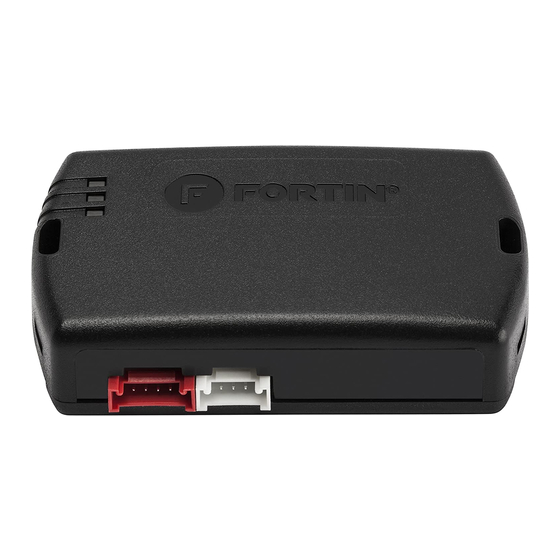
Fortin EVO-CAN Manual
Hide thumbs
Also See for EVO-CAN:
- Manual (11 pages) ,
- Quick start manual (6 pages) ,
- Suggested wiring configuration (4 pages)
Table of Contents
Advertisement
Quick Links
1 / 7
Page
A4 - A5 - Q5 - S4 - S5
AUTOMATIC TRANSMISSION
TRANSMISSION AUTOMATIQUE
PUSH
START
AUDI
A4 - A5 - Q5 - S5 - A5
Push-to-Start
Harness behind fuse box
Harnais derrière la boîte
à fusibles
(+) Ignition Black
C C opyright © 2010,
Fortin Auto Radio Inc
Harness behind fuse box
Harnais derrière la boîte
à fusibles
(+) 12V Red/Black
C C opyright © 2010,
Fortin Auto Radio Inc
Input
Entrée
Output
Sortie
INSTALLATION WITH DATA-LINK
INSTALLATION AVEC DATA-LINK
Remote
Starter/Alarm with
the Fortin Data-link
protocol.
Démarreur à
distance/alarme
avec le protocole
Data-link Fortin
4 Pin
Rev. 20120117
ADDENDUM - SUGGESTED WIRING CONFIGURATION
2009-2011
2009-2011
Driver kick panel
Twisted Pair
Panneau latéral conducteur
Paire de fils torsadés
CAN 2 LOW Orange/Brown
CAN 2 HIGH Orange/Green
C C opyright © 2010,
Fortin Auto Radio Inc
Connection always required
Branchement toujours requis
Connection not required with Data-link
Branchement non requis avec Data-Link
INSTALLATION WITHOUT DATA-LINK
INSTALLATION SANS DATA-LINK
Guide # 3879
SCHÉMA DE BRANCHEMENT SUGGÉRÉ
Parts required
1x 10A Fuse
4x 1A Diode
1x Valet key
EVO-CAN Firmware version :4.00 and newer | et plus
Key Port
Key IN Black/Yellow
C C opyright © 2010,
Fortin Auto Radio Inc
(+) Start/Stop Gray/Blue
(+) Start/Stop Black/Red
Gray/Yellow
At brake switch
Au commutateur de frein
(+) Foot Brake Red/Black
C C opyright © 2010,
Fortin Auto Radio Inc
Connect to vehicle
Branchement au véhicule
Connect to Remote-Starter/Alarm
Branchement au démarreur à
distance/Alarme
Remote
Cut off one plug of the 4 Pin
1
Starter/Alarm
Data-Link connector
Démarreur à
2
distance/alarme
Connect the Red wire to +12V
3
Connect the Black wire to
Ground
Red | Rouge +12V
Black | Noir Ground
Coupez l'extrémité du connecteur
1
4 pins Data-Link
2
Connectez le fil rouge au 12V
4 Pin
3
Connectez le fil noir à la masse
du véhicule.
Pièces requises
1x fusible 10A
4x Diodes 1A
1x Clé Valet
(+) Start/Stop Black
Back view
Vue de dos
Remove the plastic
protective cap over
the Key Port to see the
wire location. Retirez
l e c a p u c h o n d e
plastique protecteur
sur le dessus du
connecteur pour voir
la position des fils.
Advertisement
Table of Contents

Subscribe to Our Youtube Channel
Summary of Contents for Fortin EVO-CAN
- Page 1 1x 10A Fuse 1x fusible 10A 4x 1A Diode 4x Diodes 1A 1x Valet key 1x Clé Valet EVO-CAN Firmware version :4.00 and newer | et plus PUSH START AUDI A4 - A5 - Q5 - S5 - A5 2009-2011...
- Page 2 2 / 7 Page This manual may change without notice. www.ifar.ca for latest version. A4 - A5 - Q5- S4 - S5 AUTOMATIC TRANSMISSION CONTINUED | SUITE Harness Behind fuse box Replace the Remote-Starter (+) 12V Red/Black fuse with a 10A (MAX) Harnais Derrière la boîte Changez la fusible du à...
- Page 3 Pièces requises 1x 10A Fuse 1x fusible 10A 4x 1A Diode 4x Diodes 1A 1x Valet key 1x Clé Valet EVO-CAN Firmware version :4.00 and newer | et plus PUSH START AUDI A4 - A5 - S4 - S5 2009-2011 Push-to-Start...
- Page 4 4 / 7 Page This manual may change without notice. www.ifar.ca for latest version. A4 - A5 MANUAL TRANSMISSION CONTINUED | SUITE Harness Behind fuse box Replace the Remote-Starter (+) 12V Red/Black fuse with a 10A (MAX) Harnais Derrière la boîte Changez la fusible du à...
- Page 5 5 / 7 Page Ce Guide peut faire l’objet de changement sans préavis. www.ifar.ca pour la récente version. PROGRAMMING PROCEDURE | PROCÉDURE DE PROGRAMMATION PUSH START If the LED is not solid BLUE disconnect the 4 Pin connector (Data- Link) and go back to beginning of step 1.
- Page 6 6 / 7 Page This manual may change without notice. www.ifar.ca for latest version. PROGRAMMING PROCEDURE | PROCÉDURE DE PROGRAMMATION PUSH START If the LED is not solid BLUE disconnect the 4 Pin connector (Data- Link) and go back to beginning of step 1.
- Page 7 Only a computer safe logic probe or digital multimeter should be used. FORTIN ELECTRONIC SYSTEMS assumes absolutely no liability or responsibility whatsoever pertaining to the accuracy or currency of the information supplied. The installation in every case is the sole responsibility of the installer performing the work and FORTIN ELECTRONIC SYSTEMS assumes no liability or responsibility whatsoever resulting from any type of installation, whether performed properly, improperly or any other way.


Need help?
Do you have a question about the EVO-CAN and is the answer not in the manual?
Questions and answers