
Related Manuals for Kemper TRESOR


Summary of Contents for Kemper TRESOR
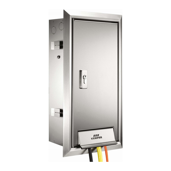
- Page 1 DE Einbau- und Bedienungsanleitung ‘TRESOR‘ Wandeinbauschrank aus Edelstahl Fig. 210 und Fig. 214 EN Installation and operating instructions ‘TRESOR‘ stainless steel built-in wall cabinet Fig. 210 and Fig. 214...
- Page 2 Schäden an der Anlage oder - sonstiger fehlerhafter Bedienung. Pflege der Schrankoberfläche: Funktionsstörungen führen können. Aggressive und scheuernde Reini- Info! Kennzeichnet zusätzliche gungsmittel können die Oberfläche Informationen und Tipps. beschädigen. 2 / 16 – K410021000001-00 / 09.2021 – © www.kemper-olpe.de...
- Page 3 2 Befestigungsschrauben (M6 x 12) muss der KEMPER TRESOR für Türschloss mit 3 Schlüsseln Strom- und Wasseranschluss durch einen FI-Schalter (Fehlerstrom 0,03A) abgesichert werden. Dies gilt für alle Steckdosen im Außen- bereich. 3 / 16 – K410021000001-00 / 09.2021 – © www.kemper-olpe.de...
- Page 4 150 mm Restwandstärke (1) erforderlich. Hinweis! Bei Verlegung der Anschlussleitung Unterputz ist eine Mindestwandstärke von 285 mm (2) erforderlich. Hinweis! Die Armatur muss mindestens 250 mm über dem höchst- möglichen Betriebswasserspiegel eingebaut werden! 4 / 16 – K410021000001-00 / 09.2021 – © www.kemper-olpe.de...
- Page 5 Tür herstellen (sämtliche metallischen Teile sind somit geerdet). Info! Metallende Gebäudeteile, zu denen auch der Tresor gehört benötigen Folgende Figuren werden mit der Schutzart IP 55 zwingend die Verbindung zum Potentialausgleich. ausgeliefert: Querschnitt dieser Leitungen ist die Hälfte des Querschnitts des Haupt- 21002015CH I 21003015CH I 21004015CH schutzleiters, mindestens jedoch 6 mm².
- Page 6 Wandscheibe bis zum Anschlag an das Auslaufgehäuse Funktionsprüfung durchführen! • schieben und mit Schraube justieren. Schlauchtülle und Adapter wie dargestellt montieren. • Gefahr! Elektroarbeiten dürfen nur von autorisiertem Fachperso- nal ausgeführt werden! 6 / 16 – K410021000001-00 / 09.2021 – © www.kemper-olpe.de...
- Page 7 Die integrierte Klappe für Schlauch- und Kabelanschluss dient zur gungspunkten an der Rückwand verbinden. Sicherheit während des Gebrauchs. Hinweis! Ventilsitz (Gewinde R ½“) muss im frostfreien Bereich liegen. Hinweis! Angaben unter Punkt 1 Mindestwandstärken sind zu beachten! 7 / 16 – K410021000001-00 / 09.2021 – © www.kemper-olpe.de...
- Page 8 Es ist aus diesem Grunde nur leichtes Zudrehen (Schließen) der Armatur erforderlich. Hinweis! Zur Sicherstellung der Funktion „Frostsicherheit“ müssen Schläuche und sonstige Anbauteile vor Beginn der Frost- periode entfernt werden! 8 / 16 – K410021000001-00 / 09.2021 – © www.kemper-olpe.de...
-
Page 9: Precautions For Installation
Don´t use malfunctions. - Other incorrect operation. chloric or acidic, grinding or acidly Info! Indicates additional infor- cleaning agents. Cleaning with a mation and tips. damp micro-fibre cloth is recom- mended. 9 / 16 – K410021000001-00 / 09.2021 – © www.kemper-olpe.de... - Page 10 Socket to fit selected Figur type or area. Mounting plate with attachment clasp and Wing-screws Trim frame and door with flap Spray protection plate 2 attachment screws (M6 x 12) Door lock with 3 keys 10 / 16 – K410021000001-00 / 09.2021 – © www.kemper-olpe.de...
- Page 11 When laying the connecting pipe within the wall, a mini- mum wall thickness of 285 mm is required! Note! The valve must be attached minimum 250 mm over the maximum of operating water surface! 11 / 16 – K410021000001-00 / 09.2021 – © www.kemper-olpe.de...
- Page 12 A slope of max. 2 % must be maintained from inside to If necessary, drill four holes and attach the cabinet (1) to the outside. rear wall using the four attachment screws provided (2) (four holes, Ø 8 mm). 12 / 16 – K410021000001-00 / 09.2021 – © www.kemper-olpe.de...
- Page 13 Push the wall plate on to the outlet housing as far as • the stop and adjust using the screw. Fit the hose sleeve and adapter as illustrated • Danger! Electrical work must be carried out only by authorised specialist personnel! 13 / 16 – K410021000001-00 / 09.2021 – © www.kemper-olpe.de...
- Page 14 Note! The valve seat (thread R ½“) must be located in the frost- free area. Note! The specifications given under Point 1 Minimum wall thicknesses must be observed! 14 / 16 – K410021000001-00 / 09.2021 – © www.kemper-olpe.de...
-
Page 15: Functional Testing
For this reason, the fitting only needs to be closed gently. Note! To ensure the correct ‘frost safety‘ function, hoses and other attachements must be removed before the start of the frost period! 15 / 16 – K410021000001-00 / 09.2021 – © www.kemper-olpe.de... - Page 16 Gebr. Kemper GmbH + Co. KG Service-Hotline +49 2761 891-800 Harkortstraße 5 www.kemper-olpe.de D-57462 Olpe info@kemper-olpe.de 16 / 16 – K410021000001-00 / 09.2021 – © www.kemper-olpe.de...
Need help?
Do you have a question about the TRESOR and is the answer not in the manual?
Questions and answers