Table of Contents
Advertisement
Via Acquanera, 29
22100 Como
tel. 031.526.566 (r.a.) fax 031.507.984
info@calpower.it
www.calpower.it
December 2016
© 2016 Fluke Corporation. All rights reserved. Specifications are subject to change without notice.
All product names are trademarks of their respective companies.
5128A
RHapid-Cal Humidity Generator
Operators Manual
Advertisement
Table of Contents

Related Manuals for Fluke CalPower 5128A


Summary of Contents for Fluke CalPower 5128A
- Page 1 22100 Como tel. 031.526.566 (r.a.) fax 031.507.984 info@calpower.it www.calpower.it 5128A RHapid-Cal Humidity Generator Operators Manual December 2016 © 2016 Fluke Corporation. All rights reserved. Specifications are subject to change without notice. All product names are trademarks of their respective companies.
- Page 2 Fluke authorized resellers shall extend this warranty on new and unused products to end-user customers only but have no authority to extend a greater or different warranty on behalf of Fluke. Warranty support is available only if product is purchased through a Fluke authorized sales outlet or Buyer has paid the applicable international price.
-
Page 3: Table Of Contents
Table of Contents Title Page Introduction .................... 1 Contact Fluke Calibration ..............2 Safety Information ................. 2 Symbols ....................4 Calibration and Repair Information ............4 General Specifications ................5 Humidity and Temperature Chamber Technical Specifications ..6 Chamber Specifications ..............6 Chamber Uniformity and Stability ............ - Page 4 5128A Operators Manual Insert the UUT ................... 23 Stabilize the Chamber and UUT ............24 Data Logger Calibration ..............24 External Reference Probe Use ............25 Sample In/Out Ports ................25 Temperature Extremes ..............25 Remote Operation ................. 26 Set Up ....................26 Remote Commands ................
-
Page 5: Introduction
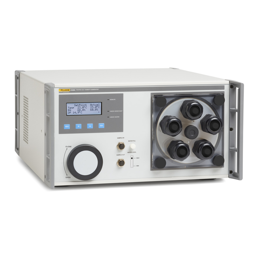
Introduction The Fluke Calibration 5128A RHapid-Cal Humidity Generator (the Product) is a precision-controlled humidity generator that produces a precise test environment to calibrate humidity sensors. Use the front-panel to control the current temperature and humidity in the chamber. The Product: •... -
Page 6: Contact Fluke Calibration
5128A Operators Manual Contact Fluke Calibration To contact Fluke Calibration, call one of the following telephone numbers: • Technical Support USA: 1-877-355-3225 • Calibration/Repair USA: 1-877-355-3225 • Canada: 1-800-36-FLUKE (1-800-363-5853) • Europe: +31-40-2675-200 • Japan: +81-3-6714-3114 • Singapore: +65-6799-5566 •... - Page 7 RHapid-Cal Humidity Generator Safety Information • Use only the mains power cord and connector approved for the voltage and plug configuration in your country and rated for the Product. • Replace the mains power cord if the insulation is damaged or if the insulation shows signs of wear.
-
Page 8: Symbols
Calibration and Repair Information If calibration or repair is necessary during the warranty period, contact an authorized Fluke Calibration Service Center to arrange for repair (see Contact Fluke Calibration). Have the Product information ready such as the purchase date and serial number to schedule the repair. -
Page 9: General Specifications
RHapid-Cal Humidity Generator General Specifications General Specifications AC mains voltage..........100 V to 240 V ±10 %, 47 to 63 Hz Power consumption ..........300 VA Required test fluid ..........Distilled water Warm-up period to meet specifications ....Twice the time since last warmed up, to a maximum of 30 minutes Internal humidifier warm-up period (time for “HEATING”... -
Page 10: Humidity And Temperature Chamber Technical Specifications
5128A Operators Manual Note The displayed dew point reading (DP) is calculated from the Product’s actual temperature and %RH readings. It is calculated as a dew point (water vapor over ° water) over the entire range, regardless if dew point is equal to or lower than 0 and at a nominal pressure of 101.325 kPa (1 atmosphere). -
Page 11: Chamber Operational Range - Maximum % Rh
RHapid-Cal Humidity Generator General Specifications Chamber Operational Range – Maximum % RH The chamber has operational range limits based on temperature and humidity settings. The table below shows the maximum % RH attainable at different temperatures. Operational Specifications Temperature rate of change – down ....1.5 °C/minute (Typical) Temperature rate of change –... -
Page 12: Product Setup
Unpack and Inspect Unpack the Product carefully and examine it for damage that could have occurred during shipment. If there is shipping damage, contact Fluke Calibration and the postal carrier immediately. Table 2 lists the equipment and the accessories that come with the Product. Make sure that all the items are in the box. -
Page 13: Fill The Product With Distilled Water
RHapid-Cal Humidity Generator Product Setup Fill the Product with Distilled Water Before the Product is connected to mains power (see Mains Voltage), fill the Product with 50 ml to 60 ml of clean, distilled water (see Figure 1). 1. Remove the fill cap from the front panel (see Front Panel). 2. -
Page 14: Mains Voltage
The Product requires mains voltage that ranges from 100 V ac to 240 V ac with frequencies from 50 Hz to 60 Hz. The Product comes with the appropriate line power plug for the country of purchase. See Table 3 for the mains line power plug types available from Fluke Calibration. - Page 15 RHapid-Cal Humidity Generator Product Setup Table 3. Available Mains Power Plug Types LC-3 LC-1 LC-5 LC-4 LC-6 LC-7 LC-42 hwr039.eps Type Fluke Calibration Option Number North America LC-1 Universal Euro LC-3 United Kingdom LC-4 Switzerland LC-5 Australia LC-6 South Africa...
-
Page 16: The Product
5128A Operators Manual The Product This section describes front-panel operation, the working chamber, the display and control panel, and the rear panel. See Tables 4, 5, 6, and 7. Table 4. Front Panel ibw001.eps Item Name Description Refer to Display and Control Panel for a full ... - Page 17 RHapid-Cal Humidity Generator The Product Table 5. Working Chamber ibw023.eps Item Name Description Causes the air to circulate in a certain manner that gives better temperature and humidity uniformity inside the insert. The volume inside the insert is the working area where the Product guarantees its performance per the Product ...
- Page 18 5128A Operators Manual Table 6. Display and Control Panel 5128A ibw002.eps Item Name Description Shows: • Set points for temperature and humidity • Actual temperature and humidity Display • Calculated dew point • Lower right corner: Display messages during operation at first startup.
-
Page 19: Startup And Main Screen
RHapid-Cal Humidity Generator The Product Table 6. Display and Control Panel (cont.) Item Name Description EXIT Hold down for 4 seconds (from any screen) to return to the main screen. Button Remote: Indicates communication over the USB serial interface. Check Desiccant: Indicates there may be issues with the dry gas sub- system. -
Page 20: Probe Calibrate Screen
5128A Operators Manual Probe Calibrate Screen The probe calibrate screen shows the probe offsets for temperature and humidity and is used in the Product-adjustment process. Use the probe calibrate screen to load in a temperature offset and humidity offset to adjust the Product chamber output. - Page 21 RHapid-Cal Humidity Generator The Product Table 7. Rear Panel F1A 250V FUSE 12 VDC DRAIN ibw003.eps Item Name Description Fan inlet/outlet holes Do not block the inlet/outlet holes. Fans The two fans provide internal cooling to the Product. Power supply fan access Provides cooling for the internal power supply.
-
Page 22: Operation
5128A Operators Manual Table 7. Rear Panel (cont.) Item Name Function Contains two mains fuses and the receptacle for the mains Fuse Holder and Mains power cord. Use an ac mains supply appropriate for the Power Cord Receptacle voltage range and region of use. See Mains Voltage and Maintenance. -
Page 23: Door Styles
1. Push the “1” side of the power switch on the rear panel. 2. Monitor the startup screen for errors as the Product powers up. If an error shows, see Troubleshooting and Error Code. Contact Fluke Calibration for unresolved errors, see Contact Fluke Calibration. -
Page 24: Turn The Product Off
5128A Operators Manual Turn the Product Off Push the power switch on the rear panel to the “0” position to turn off the Product. If the chamber dew point is greater than the ambient temperature, to avoid condensation, do not open the chamber door for 1 hour so that the chamber comes to room temperature. -
Page 25: Condensation Prevention
RHapid-Cal Humidity Generator Operation Condensation Prevention The Product has a condensation-prevention feature that minimizes the possibility of condensation when certain user settings are called for. At high humidities, when the chamber dew point is within 2 °C of the actual chamber temperature, a CAUTION message shows on the lower right hand corner of the display and the controller slows the rate of temperature and humidity change. -
Page 26: Calibrate Uuts
5128A Operators Manual Calibrate UUTs The subsequent sections explain how to do calibrations on humidity probes or UUTs. Recommended Calibration Sequences These recommendations ensure fast, repeatable calibrations of humidity sensors: 1. Do lower-relative humidity calibrations first and ramp up to the higher- humidity levels on each subsequent calibration step. -
Page 27: Insert The Uut
RHapid-Cal Humidity Generator Calibrate UUTs Insert the UUT To make sure the UUT is inserted into the Product chamber correctly, use the working volume template that is included at the end of this manual, see Figure 11. Use one of the probe ports on the chamber door to insert the UUT into the chamber: 1. -
Page 28: Stabilize The Chamber And Uut
5128A Operators Manual For short probes without an available cable, insert the probe into the door as far as possible and do calibrations at or near ambient temperature. This eliminates temperature gradients between the UUT and the chamber. Under these conditions, where the UUT probe is not fully immersed in the working volume, an external reference probe that is inserted at the same depth should be used to ensure the best calibration. -
Page 29: External Reference Probe Use
Sample In/Out port lines, otherwise the lines must be heated to 5 °C above the chamber temperature. Fluke Calibration recommends that the gas sample is returned back to the Product through the Sample In port. -
Page 30: Remote Operation
The drivers are normally part of the Windows operating system. Windows detects the interface as a virtual COM port. If Windows is unable to find the driver, contact Fluke Calibration for technical support. Refer to Contact Fluke Calibration. -
Page 31: Transport The Product
Product otherwise. Always transport the product in its horizontal position. Ship the Product Fluke Calibration recommends that the Product be drained of water before shipping. To do so, unfasten the drain screw cap on the rear of the Product, and drain the water by slightly tilting the Product. -
Page 32: Desiccant Replacement
3. Loosen the rear seal of the desiccant by gently nudging the front of the desiccant in various directions (up/down, left/right). 4. Pull the spent cartridge out of the Product and insert a new cartridge. Additional desiccant cartridges are available from Fluke Calibration. ibw026.eps Figure 5. Change the Desiccant Cartridge... -
Page 33: Water Level
RHapid-Cal Humidity Generator Maintenance Water Level Use the Product only when the water level is between Max and Min on the front- panel indicator as viewed with the Product off or in Standby state. Check the water level when the Check Water indicator is lit on the front panel or the display shows . - Page 34 5128A Operators Manual To replace the mains fuse, refer to Figure 6: 1. Disconnect the mains power cord. 2. With a standard screwdriver, release the fuse holder door . 3. Pull out the fuse holder . 4. If necessary, replace the fuse . 5.
- Page 35 RHapid-Cal Humidity Generator Maintenance The Product has a fuse for the 12 V dc transducer power output located in the rear panel. Replace only with a 1 A Fast Blow fuse (F1A 250V 5x20mm). To change the fuse, see Figure 7. ibw024.eps Figure 7.
-
Page 36: Calibration
Fluke 1586A Super-DAQ Precision Temperature Readout thermistor uncertainty Scanner with DAQ-STAQ multiplexer 0.01 °C calibration Thermistor Fluke 5611T 8 probes are required uncertainty Positions four of the thermistor probes in a square pattern at the rear Thermistor of the working area, and... -
Page 37: Using A Chilled Mirror Probe
RHapid-Cal Humidity Generator Calibration Using a Chilled Mirror Probe There are different ways to use a chilled mirror with the Product. The subsequent sections outline several of them: • You can draw a gas sample from the chamber as shown in Figure 8. The tube to extract the sample is inserted into one of the ports. - Page 38 5128A Operators Manual • If the chilled mirror has a remote sensing head that fits into one of the door ports, insert the remote head into the door as shown in Figure 9. Ensure that the remote head sensor is inserted into the working volume of the chamber. There is sufficient gas flow within the chamber such that an external pump is normally not needed in this situation.
- Page 39 RHapid-Cal Humidity Generator Calibration • A gas sample from the Sample Out port can be drawn with a chilled mirror that has a pump, returning the gas into the Sample In port. A flow rate of 0.1 liters to 0.5 liters per minute is usually adequate. Ensure the chosen flow rate does not cause excessive chamber temperature non-uniformity.
-
Page 40: As Found Data Collection
5128A Operators Manual As Found Data Collection For each step in Table 11: 1. Set the Product to the calibration set point shown in Table 11. Allow 35 minutes for stabilization. 2. Take the dew point measurement with the chilled mirror. 3. -
Page 41: Load Temperature And Humidity Offsets Into The Product
If there are any observed errors in the As Found data that are greater than 70 % of tolerance, temperature and humidity offsets can be entered into the Product. If the subsequent procedure cannot bring the Product into tolerance, contact Fluke Calibration. -
Page 42: Temperature Uniformity Verification
5128A Operators Manual Temperature Uniformity Verification The temperature uniformity verification uses the temperature data collected when measuring each of the set points in Table 11. It compares each of the 8 temperature probes against the average of the 8 probes. Temperature uniformity at each of the 8 measurement points is defined as absolute maximum of Tx –... -
Page 43: Error Messages
RHapid-Cal Humidity Generator Error Messages Problem Possible Cause Solution Desiccant cartridge needs to be Shut off power, open the desiccant replaced. cartridge. Inspect. Replace if the normally blue cartridge material is pink. Door not properly sealed, causing a Tighten door. leak. -
Page 44: Error Codes
Humidity generator is above allowed limit. Check water supply or “HumGen High Limit” ambient conditions. “EEPROM Cfg Reset” Unit has reset its configuration to factory default, review settings. Factory calibration has been reset to default. Please contact “EEPROM Cal Reset” Fluke Calibration. -
Page 45: User-Replaceable Parts And Accessories
User-Replaceable Parts and Accessories Table 15 lists the part numbers of each user-replaceable part or accessory for the Product. For more information on these items and accessories, refer to Contact Fluke Calibration. Table 15. User-Replaceable Parts and Accessories Fluke Calibration Part... - Page 46 1.00 inch 4.30 inches 4.88 inches FRONT PANEL FACE OF FLUKE 5128A FRONT RIGHT CORNER OF FLUKE 5128A Figure 11. Working Volume Template...
Need help?
Do you have a question about the CalPower 5128A and is the answer not in the manual?
Questions and answers