Advertisement
Quick Links
Instruction Manual
Portable Vibrometer
SmartVibro Series
Model: VM-4424S
VM-4424H
- 1 -
Manufacture:
IMV CORPORATION
Document No.:
TVE-6-3791E
th
Revision Date:
18
Page:
47
Version:
3.0.0
VM-4424S/H Instruction Manual
(Compatible with Version 2.16 or later)
June, 2021
Advertisement

Related Manuals for IMV SmartVibro Series


Summary of Contents for IMV SmartVibro Series
- Page 1 Instruction Manual Portable Vibrometer SmartVibro Series Model: VM-4424S VM-4424H Manufacture: IMV CORPORATION Document No.: TVE-6-3791E Revision Date: June, 2021 Page: Version: 3.0.0 VM-4424S/H Instruction Manual - 1 - (Compatible with Version 2.16 or later)
-
Page 2: Important Notice
Revision History Date Ver. Details Mar, 2012 1.0.0 New Issue. (1) Corrected Figures and phrases. Mar, 2012 1.0.1 (2) Added optional accessories. (1) Added Preparation (3-1). Apr, 2012 1.0.2 (2) Added Definitions (10), including H-func. Aug, 2012 1.0.3 Added Title for BRG and H-func. Oct, 2012 1.0.4 Corrected Unit Display. - Page 3 INDEX 1. Introduction ..........................4 1-1. Panel Description ......................5 1-2. Package Contents ......................6 2. Outline ............................. 7 2-1. SmartVibro Overview ....................... 7 2-2. Features ..........................7 3. Measurement ........................... 8 3-1. Before Getting Started ...................... 9 3-2. Measurement Screen ....................... 10 3-3.
- Page 4 Turn off the power switch and unplug the power cable from outlet as soon Warning as possible, please contact the agency or IMV. To reduce risk of injury, take it to a qualified serviceman when service or repair is required.
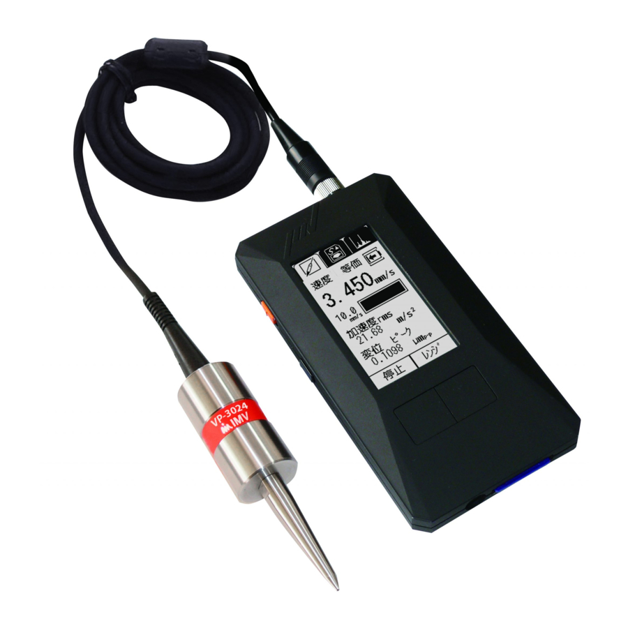
- Page 5 1-1. Panel Description VM-4424 is available in Standard Model (VM-4424S) or High-End Model (VM-4424H). Icons appeared on the display are different in each model. Each screen display example is shown below. High-end model has these two icons when the machine is turned on. VM-4424 can be switched freely between Japanese and English.
- Page 6 1-2. Package Contents Product and Accessories for the VM-4424. (1) Basic Product and Accessories Products Model Note Figure VM-4424S SmartVibro VM-4424H Piezoelectric Pickup VP-4316 Acceleration Type Handheld probe (with a nut) Probe - φ6×195mm 1.5m cable with a plug at one end.
- Page 7 2. Outline 2-1. SmartVibro Overview SmartVibro is an acceleration meter placing emphasis on analysis, which is equipped with functions of H-function measurement, i.e., envelope processing. This machine serves various uses in measurement including checking the machines and equipment from various points of view. With SmartVibro, you can not only analyze the bearing, but also measure the acceleration amount and check fluctuation components in low-speed rotating machinery bearings.
- Page 8 3. Measurement The names of each part of the main unit are as shown in Fig.3-1. DC OUT: AC OUT: DC output of measurement data AC output of measurement data. Connector: Attach the pickup cable. Power Switch: LCD Panel: Power ON/OFF Displays and sets measured values.
- Page 9 3-1. Before Getting Started (1) You can select the computing method for velocity, acceleration, and displacement. Refer to the section 4-2 for more details. Initial settings are as follows: ■ Acceleration (ACC): ■ Velocity: ■ Displacement: Caution For measurement of the vibration severity, ake the following settings.
- Page 10 3-2. Measurement Screen Turn on the SmartVibro by sliding an orange switch on the left side of the device, initial screen (Fig.3-3) will appear. Operate the device by using the touch screen and two function buttons. (Japanese) (English) Fig.3-3 Initial Screen (1) Standard Measurement Mode VM-4424S is equipped with this mode only.
- Page 11 3-3. Operations during Measurement Touching “Start” on the touch screen or press “Measurement Button” in Fig.3-3 would start measurement. The screen displays measurement status. (Fig.3-4)。 Once touch “Hold” on the touch screen or press “Function Button” would hold measurement and the display (AC output when stopped is not retained). Touch here to zoom in.
- Page 12 How to Zoom In Touch the range bar area on the screen to zoom in the image (Fig.3-4). To zoom out, touch the same area again (Fig.3-6). <Excessive Input State> When this mark display appears, the measured value is inaccurate. Please measure with the mark disappearing.
- Page 13 4. Setting This section explains how to make various settings such as measurement mode. As shown in Fig.4-1, the setting screen will appear when press “Function Button” when “setting” is indicated in the function indicator (Fig 4-2). (Japanese) (English) Fig.4-1 “Setting”...
- Page 14 The setting screen can be switched by touching the icon at the top of the screen (Fig.4-3). Setting Icon (Japanese) (English) Fig.4-3 Switching the setting screen Switching is in the following order. VM-4424S/H Instruction Manual - 14 - (Compatible with Version 2.16 or later)
- Page 15 4-1. Mode Setting When “Vel.” is selected for the Mode (Fig.4-4), the physical amount is shown at the top of the measurement screen. Also, the enlarged screen will show the physical amount accordingly. (Japanese) (English) Fig.4-4 Mode Setting In “Mode”, the setting mode changes in the following order each time the button is touched.
- Page 16 Refer below for explanation of BRG and Hfunc. ● BRG (Bearing) In BRG mode, processing is performed with a filter fixed in the 1kHz to 10kHz band. In VM-4416, the range in this mode was A to E, and the unit was dimensionless. However, VM-4424 displays the acceleration with the original physical quantity.
- Page 17 4-2. Calculation Setting You can set how to indicate the physical amount of measurement results in calculation setting (Calc.). As you touch “Set” in Fig.4-2, Fig.4-6 will appear. (Japanese) (English) Fig.4-6 Calculation Setting The calculation method selected in Fig.4-6 will be displayed on the screen (Fig.4-7). (Japanese) (English) Fig.4-7 Example of the Setting Screen...
- Page 18 Calculation settings change each time the button is touched. Switching is in the following order. Peak Peak DISP A brief Description of each Calculation Method rms: “rms” is “Root Mean Square”. This is the square root of the mean of the squares of the time-series data gathered from measurement.
- Page 19 4-3. Filter Change the settings of high-pass (HPF) and low-pass filters (LPF). Pressing “Set” would bring you to the screen indicated in Fig.4-8. By touching the triangles on the screen ( ), you can change the frequency of each filter. 5 Hz 5 Hz 5 Hz...
- Page 20 4-4. Setting of Auto Range, H-function Coupling, and Pickup Sensitivity To set Auto Range, H-function Coupling and Pickup Sensitivity, select tab on the setting screen. (Japanese) (English) Fig.4-9 Setting Page of Auto Range, H-function Coupling, and Pickup Sensitivity 4-4-1. Setting of Auto Range When auto range is "ON", range will be adjusted automatically during measurement (Fig.4-9).
- Page 21 4-4-2. Setting of H-function Coupling Select the coupling of the H-function from AC and DC. Touching “DC” of H-function coupling in Fig.4-9 switches between “DC” and “AC”. The ACOUT output always outputs only the fluctuation component, but the displayed value and the DC output differ depending on this setting (refer to section 4-1). 4-4-3.
- Page 22 4-5. Sensitivity Setting of AC and DC Output and Volume Adjustment To set the sensitivity of AC Output and DC Output, select the tab on the setting screen (Fig.4-12). (Japanese) (English) Fig.4-12 AC and DC Output Sensitivity Setting Page Touch “Next Page” on the setting screen shown in Fig.4-12 to move to the second page. There are 4 pages in total, and every time you touch “Next Page”, the screen is change as follow.
- Page 23 The AC output sensitivity specifies the full scale for the ACOUT voltage value. Touching the “Set” button will display Fig.4-14. For each of velocity, acceleration, and displacement, set the value of voltage 1V. In the example shown in Fig.4-14, the settings are as follows. Velocity: “1V”...
- Page 24 The setting method is the same as AC output sensitivity. The value is switched as shown in Fig.4-16 by pressing the button with the number displayed. Vel. 15000 1500 mm/s Acc. Disp. 0.15 mmp-p Fig.4-16 DC Output Sensitivity Setting Caution Cautions when using AC output and DC output (1) When performing measurement using AC output and DC output, be sure to set Auto Range to “OFF”.
- Page 25 (Japanese) (English) Fig.4-17 Setting Screen of Battery Type, Auto Power Off, and Contrast 4-6-1. Setting of Battery Type Select the battery type, Ni-MH (rechargeable Ni-Cd battery) or LR6/R6 (alkaline battery). Since battery life indication depends on this battery type setting, the correct battery type needs to be selected.
- Page 26 4-7. Language Setting Touch “Next Page” on the setting screen shown in Fig.4-17 to move to the third page (Fig.4-18). (Japanese) (English) Fig.4-18 Language Setting and Version Information 4-7-1. Language Setting Select “en” for English. Once you restart the device, the display will be changed into English.
- Page 27 4-7-2. Version Information You can check the firmware version. Touch the “View” button next to the version in Fig.4-18 to display the version information (Fig.4-19). (Japanese) (English) Example of Version Display 02.16.2021 Fig.4-19 Display of Version If you contact us about the product, we may check the version of holding VM-4424S/H. Please check the version in advance with this function.
- Page 28 4-8. Password Function 4-8-1. Password Setting Touch “Next Page” on the setting screen shown in Fig.4-18 to move to the forth page (Fig.4-20). Password lock can be set so that only the administrator can change the settings. Note that the password is not set when shipped from the factory ("OFF"). (Japanese) (English) Fig.4-20 Password Setting (Password “OFF”)
- Page 29 (Japanese) (English) Fig.4-21 Password Input (Japanese) (English) Password Setting (Password “ON”) Fig.4-22 VM-4424S/H Instruction Manual - 29 - (Compatible with Version 2.16 or later)
- Page 30 4-8-2. Password Input While password is set, if you press the “Setting” button, Fig 4-23 will show “Password entry”. Please input 4 digits number, and press the return button ( ). If password is correct, the setting page will be displayed. If password is not correct, then the “Password entry”...
- Page 31 4-9. Battery Indicator When “PwrInfo” is displayed, press the button or touch the screen to check the power information (Fig.4-24 and Fig.4-25). (Japanese) (English) Fig.4-24 “PwrInfo” Indication (Japanese) (English) Fig.4-25 Battery Information VM-4424S/H Instruction Manual - 31 - (Compatible with Version 2.16 or later)
- Page 32 5. FFT and Data Save VM-4424H is equipped with FFT and waveform saving functions. These functions are described below. FFT: FFT Mode is activated when this tab is selected. Data Save: Data Save Mode is activated when this tab is selected. Waveform data will be stored in the SD card as plain text.
- Page 33 5-1. FFT 5-1-1. FFT Indication Selecting FFT tab will show the screen Fig.5-2. (Japanese) (English) Fig.5-2 FFT Menu (1) FFT Graph Y-axis shows the physical amount of the measurement result indicated above the graph (Velocity in Fig 5-2). X-axis indicates frequency. (2) Maximum frequency and its value.
- Page 34 (Japanese) (English) Fig.5-3 Detail of FFT (1) The cursor, indicated as a black dot on the screen, will move from one peak to another peak (2) MAX: Maximum value of the gathered data. Cur: Value pointed by the cursor. (3) Slide the cursor. Regarding the Range when using FFT When “Auto Range”...
- Page 35 5-1-2. FFT Setting On VM-4424H, “Next Page” is displayed on Auto Range setting screen. When “Next Page” is touched, the setting screen for “Save Point” and “FFT Line” is displayed (Fig.5- “FFT Line” shows a frequency resolution. You can select from 6.25Hz, 12.5Hz, and 25Hz.
- Page 36 (Japanese) (English) Fig.5-5 Waveform Data Gathering Start Pressing “Measurement Button” or touching “Start” in Fig.5-5 starts gathering the data. (Japanese) (English) Fig.5-6 Waveform Data Gathering VM-4424S/H Instruction Manual - 36 - (Compatible with Version 2.16 or later)
- Page 37 In Fig.5-6, when press “Function Button” or touch “AqStart” on the touch screen, data acquisition actually starts. When data acquisition is complete, the screen shown in Fig.5-7 appears. Press “Function Button” or touch “Save” on the touch screen to save the data to SD. Saving to SD is numbered in order starting from “0000”...
- Page 38 Caution Precautions when Saving Waveform Data (1) Waveform data is the physical amount displayed at the top in measurement mode. Display the physical amount you want to collect at the top of the measurement mode, and then save the waveform data. (2) The range setting is not relevant when saving waveform data.
- Page 39 The time that can be specified is “0.1s”, “0.2s”, “0.5s” and “1s”. The time changes each time you touch. 0.1s 0.2s 0.5s The number of data acquisitions is 51,200 per second and is proportional to the save point, so calculate the time axis based on this (see the table below). Save Point data acquisitions 0.1s...
- Page 40 6. Specifications 6-1. SmartVibro Sampling Frequency 51.2kHz Acceleration (ACC), Velocity (VEL) and Displacement (DISP): Depends on the filter setting (*1) Setting Range of HPF: 5 to 999Hz 1Hz Step (*) Frequency Range Setting Range of LPF: 100 to 10,000Hz 100Hz Step (*) * Factory Default is “HPF: 5Hz”...
- Page 41 6-2. Outer Dimensions of SmartVibro Unit: mm VM-4424S/H Instruction Manual - 41 - (Compatible with Version 2.16 or later)
- Page 42 6-3. Pickup Detecting Method Piezoelectric Acceleration Type Detection Direction 1 direction Sensitivity 9pC/(m/s Ambient Conditions -10 to 50°C (No freezing or condensation) Case Material Aluminum Cable Connection 1.5m Curl Cable Connector Structure Dust and Splash Proof Dimensions refer to section 6-4. Dimensions and Weight Weight: Pickup: Approx.
- Page 43 7. Troubleshooting (1) In case of over range When the over range icon appeared during use, modify the range setting as explained in Fig.3-5. Over range will be adjusted automatically in the auto range setting. If the over range icon is frequently lit in Auto Range “ON”, use manual range (Auto Range is set “OFF”).
- Page 44 9. How to Fix the Pickup and Frequency Characteristics When a vibration pickup is attached to a vibrating body, a single vibration system is formed at the contact area, and the natural frequency of that system is determined. This is called the contact resonance frequency.
- Page 45 10. Definitions rms: Root mean square. This is the square root of mean of the values x , for a set of measuring data x ,…, x , namely ISO standard sets rms of vibration velocity as evaluation criteria of the vibration velocity, which is also known as vibration severity.
- Page 46 Envelope Waveform: Envelope waveform means the peak trajectory of the vibration waveform. For example, vibration due to rolling bearing deterioration occurs in DC to 1kHz band due to rotation, and is modulated by the natural frequency (2k to 15kHz) of the bearing and transmitted to the bearing housing.
- Page 47 Appendix Filter Characteristic The filter characteristics (typical values) for VM-4424S/H are as follows. (1) High Pass Filter (HPF) Characteristic (Acceleration (ACC) Typical Value) Frequency [Hz] (2) Low Pass Filter (LPF) Characteristic (Acceleration (ACC) Typical Value) Frequency [Hz] VM-4424S/H Instruction Manual -...
Need help?
Do you have a question about the SmartVibro Series and is the answer not in the manual?
Questions and answers