
Related Manuals for IMV SmartVibro VM-7024H


Summary of Contents for IMV SmartVibro VM-7024H
- Page 1 Instruction Manual Portable Vibrometer SmartVibro Series Model: VM-7024H Manufacture: IMV CORPORATION Document No.: TVE-6-3792E Revision Date: June, 2021 Page: Version: 3.0.0 VM-7024H Instruction Manual - 1 - (Compatible with Version 2.16 or later)
-
Page 2: Important Notice
Revision History Date Ver. Details May, 2012 1.0.0 New Issue. July, 2012 1.0.1 Corrected Figures and phrases. August, 2012 1.0.2 Corrected Phrases. Add the sampling frequency for Data Save. Oct, 2012 1.0.3 Add the Notation for Self-Check And FFT. Dec, 2012 1.5.0 Add “Password Function”(4-14). - Page 3 INDEX 1. Introduction ..........................4 1-1. Panel Description ......................5 1-2. Package Contents ......................6 2. Outline ............................. 7 2-1. SmartVibro Overview ....................... 7 2-2. Features ..........................7 3. Measurement ........................... 8 3-1. Before Getting Started ...................... 9 3-2. Measurement Screen ....................... 10 3-3.
- Page 4 Turn off the power switch and unplug the power cable from outlet as soon Warning as possible, please contact the agency or IMV. To reduce risk of injury, take it to a qualified serviceman when service or repair is required.
- Page 5 1-1. Panel Description VM-7024H can be switched freely between Japanese and English. Each screen display example is shown below. (Japanese) (English) VM-7024H Instruction Manual - 5 - (Compatible with Version 2.16 or later)
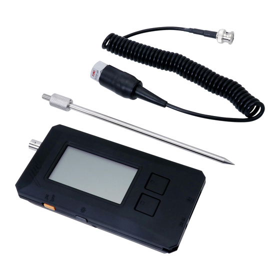
- Page 6 1-2. Package Contents Product and Accessories for the VM-7024H. (1) Basic Product and Accessories Products Model Note Figure SmartVibro VM-7024H Piezo resistive Pickup VP-7000L Acceleration Type 3m straight cable with Smart Vibro CP-7000 metal connectors at both Cable ends. 1.5m cable with a plug at one end.
- Page 7 2. Outline 2-1. SmartVibro Overview SmartVibro is a portable vibration meter with high-sensitivity and accuracy to measure micro vibration of super low frequency. Its application varies widely; measuring and analyzing vibrations, evaluation and maintenance of the ground and/or floor of various architectural constructions, precision machines in the laser and semiconductor industries, and low-speed machineries in energy harvesting and hydroelectric generation.
- Page 8 3. Measurement The names of each part of the main unit are as shown in Fig.3-1. DC OUT: AC OUT: DC output of measurement data AC output of measurement data. Connector: Attach the pickup cable. Power Switch: LCD Panel: Power ON/OFF Displays and sets measured values.
- Page 9 3-1. Before Getting Started (1) You can select the computing method for velocity, acceleration, and displacement. Refer to section 4-2 for more details. Initial settings are as follows: ■ Acceleration (ACC): ■ Velocity: ■ Displacement: Caution If you are familiar with our VM-7000L, EQP setting for the displacement is highly recommended.
- Page 10 3-2. Measurement Screen Turn on the SmartVibro by sliding an orange switch on the left side of the device, initial screen (Fig.3-3) will appear. Operate the device by using the touch screen and two function buttons. (Japanese) (English) Fig.3-3 Initial Screen (1) Standard Measurement Mode You can measure the OA value of acceleration in this mode.
- Page 11 3-3. Operations during Measurement Touching “Start” on the touch screen or press “Measurement Button” in Fig.3-3 would start measurement. The screen displays measurement status (Fig.3-4). Once touch “Hold” on the touch screen or press “Function Button” would hold measurement and the display (AC output when stopped is not retained). Touch here to zoom in.
- Page 12 How to Zoom In Touch the range bar area on the screen to zoom in the image (Fig.3-4). To zoom out, touch the same area again (Fig.3-6). <Excessive Input State> When this mark display appears, the measured value is inaccurate. Please measure with the mark disappearing.
- Page 13 4. Setting This section explains how to make various settings such as measurement mode. As shown in Fig.4-1, the setting screen will appear when press “Function Button” when “setting” is indicated in the function indicator (Fig.4-2). (Japanese) (English) Fig.4-1 “Setting” in the Function Indicator (Japanese) (English) Fig.4-2 Mode and Calculation Setting Screen...
- Page 14 The setting screen can be switched by touching the icon at the top of the screen (Fig.4-3). Setting Icon (Japanese) (English) Fig.4-3 Switching the setting screen Switching is in the following order. If “Next Page” is displayed on the setting screen, touch it to display the settings for the second and subsequent pages (Fig.4-3).
- Page 15 4-1. Mode Setting When “Vel.” is selected for the Mode (Fig.4-4), the physical amount is shown at the top of the measurement screen. Also, the enlarged screen will show the physical amount accordingly. (Japanese) (English) Fig.4-4 Mode Setting In “Mode”, the setting mode changes in the following order each time the button is touched.
- Page 16 4-2. Calculation Setting You can set how to indicate the physical amount of measurement results in calculation setting (Calc.). As you touch “Set” in Fig.4-2, Fig.4-6 will appear. (Japanese) (English) Fig.4-6 Calculation Setting The calculation method selected in Fig.4-6 will be displayed on the screen (Fig.4-7). (Japanese) (English) Fig.4-7 Example of the Setting Screen...
- Page 17 Calculation settings change each time the button is touched. Switching is in the following order. Peak Acc. Vel. Peak Disp. (1) A brief Description of each Calculation Method rms: “rms” is “Root Mean Square”. This is the square root of the mean of the squares of the time-series data gathered from measurement.
- Page 18 4-3. Filter Change the settings of high-pass (HPF) and low-pass filters (LPF). Pressing “Set” would bring you to the screen indicated in Fig.4-8. By touching the triangles on the screen ( ), you can change the frequency of each filter. (Japanese) (English) Fig.4-8 Example of Filter Setting...
- Page 19 4-4. Setting of Auto Range, Self-check, and Averaging To set Auto Range, Self-check and Averaging, select tab on the setting screen. (Japanese) (English) Fig.4-9 Setting Page of Auto Range, Self-check, and Averaging Touching “Next Page” changes to the data saving and FFT function setting screen for the second page.
- Page 20 4-4-2. Self-Check Mode By reversing the pickup vibration detection direction in the direction of gravitational acceleration (vertical) and checking the static acceleration of ±9.8m/s (±1G), it is possible to easily determine whether there is a pickup abnormality. (1) Connect an oscilloscope or digital voltmeter to DCOUT. ※Device is select "DC measurement mode".
- Page 21 4-4-3. Setting of Averaging VM-7024H is able to select the conditions of averaging of the measurement results from "Fast", "Normal", or "Slow". This setting specifies the quantity of data to be used in averaging. The number of data increases in the order of “Fast”, “Normal”, and “Slow”. “Slow” is recommended to minimize fluctuation of measurement results for the case that low- frequency components dominate the results.
- Page 22 4-5. Sensitivity Setting of AC and DC Output To set the sensitivity of AC Output and DC Output, select the tab on the setting screen (Fig.4-13). (Japanese) (English) Fig.4-13 AC and DC Output Sensitivity Setting Page Touch “Next Page” on the setting screen shown in Fig.4-13 to move to the second page. There are 4 pages in total, and every time you touch “Next Page”, the screen is change as follow.
- Page 23 The AC output sensitivity specifies the full scale for the ACOUT voltage value. Touching the “Set” button will display Fig.4-15. For each of velocity, acceleration, and displacement, set the value of voltage 1V. In the example shown in Fig.4-15, the settings are as follows. Velocity: “1V”...
- Page 24 The setting method is the same as AC output sensitivity. The value is switched as shown in Fig.4-17 by pressing the button with the number displayed. Vel. 1500 mm/s Acc. Disp. 0.15 mmp-p Fig.4-17 DC Output Sensitivity Setting Caution Cautions when using AC output and DC output (1) When performing measurement using AC output and DC output, be sure to set Auto Range to “OFF”.
- Page 25 (Japanese) (English) Fig.4-18 Setting Screen of Battery Type, Auto Power Off, and Contrast 4-6-1. Setting of Battery Type Select the battery type, Ni-MH (rechargeable Ni-Cd battery) or LR6/R6 (alkaline battery). Since battery life indication depends on this battery type setting, the correct battery type needs to be selected.
- Page 26 4-7. Language Setting Touch “Next Page” on the setting screen shown in Fig.4-18 to move to the third page (Fig.4-19). (Japanese) (English) Fig.4-19 Language Setting and Version Information 4-7-1. Language Setting Select “en” for English. Once you restart the device, the display will be changed into English.
- Page 27 4-7-2. Version Information You can check the firmware version. Touch the “View” button next to the version in Fig.4-19 to display the version information (Fig.4-20). (Japanese) (English) Example of version display 02.16.2021 Fig.4-20 Display of Version If you contact us about the product, we may check the version of holding VM-7024H. Please check the version in advance with this function.
- Page 28 4-8. Password Function 4-8-1. Password Setting Touch “Next Page” on the setting screen shown in Fig.4-19 to move to the forth page (Fig.4-21). Password lock can be set so that only the administrator can change the settings. Note that the password is not set when shipped from the factory ("OFF"). (Japanese) (English) Fig.4-21 Password Setting (Password “OFF”)
- Page 29 (Japanese) (English) Fig.4-22 Password Input (Japanese) (English) Password Setting (Password “ON”) Fig.4-23 VM-7024H Instruction Manual - 29 - (Compatible with Version 2.16 or later)
- Page 30 4-8-2. Password Input While password is set, if you press the “Setting” button, Fig 4-24 will show “Password entry”. Please input 4 digits number, and press the return button ( ). If password is correct, the setting page will be displayed. If password is not correct, then the “Password entry”...
- Page 31 4-9. Battery Indicator When “PwrInfo” is displayed, press the button or touch the screen to check the power information (Fig.4-25 and Fig.4-26). (Japanese) (English) Fig.4-25 “Pwr Info” Indication (Japanese) (English) Fig.4-26 Battery Information VM-7024H Instruction Manual - 31 - (Compatible with Version 2.16 or later)
- Page 32 5. FFT and Data Save VM-7024H is equipped with FFT and waveform saving functions. These functions are described below. FFT: FFT Mode is activated when this tab is selected. Data Save: Data Save Mode is activated when this tab is selected. Waveform data will be stored in the SD card as plain text.
- Page 33 (Japanese) (English) Fig.5-2 Detail of FFT (1) The cursor, indicated as a black dot on the screen, will move from one peak to another peak (2) MAX: Maximum value of the gathered data. Cur: Value pointed by the cursor. (3) Slide the cursor. Frequency range of the FFT is 0.25 to 100Hz. Regarding the Range when using FFT When “Auto Range”...
- Page 34 5-1-2. FFT Setting Select tab and touch “Next Page”, the setting screen for “Save Point” and “FFT Line” is displayed (Fig.5-3). “FFT Line” shows a frequency resolution. You can select from 0.25Hz, 0.5Hz, and 1Hz. (1) About FFT processing time At FFT mode, it may take much time to execute FFT calculation.
- Page 35 (Japanese) (English) Fig.5-4 Waveform Data Gathering Start Pressing “Measurement Button” or touching “Start” in Fig.5-4 starts gathering the data. (Japanese) (English) Fig.5-5 Waveform Data Gathering VM-7024H Instruction Manual - 35 - (Compatible with Version 2.16 or later)
- Page 36 In Fig.5-5, when press “Function Button” or touch “AqStart” on the touch screen, data acquisition actually starts. When data acquisition is complete, the screen shown in Fig.5-6 appears. Press “Function Button” or touch “Save” on the touch screen to save the data to SD. Saving to SD is numbered in order starting from “0000”...
- Page 37 Caution Precautions when Saving Waveform Data (1) Note that the sampling frequency is 2048Hz when saving waveform data (measurement mode is 4096Hz). (2) Waveform data is the physical amount displayed at the top in measurement mode. Display the physical amount you want to collect at the top of the measurement mode, and then save the waveform data.
- Page 38 The time that can be specified is “5s”, “10s”, “25s” and “50s”. The time changes each time you touch. The number of data acquisitions is 2,048 per second and is proportional to the save point, so calculate the time axis based on this (see the table below). Save Point Data Acquisitions 10,240...
- Page 39 6. Conversion Table Displacement [mmp-p] Acceleration [m/s Displacement [mmp-p] Velocity [mm/s] Acceleration [m/s Frequency [Hz] VM-7024H Instruction Manual - 39 - (Compatible with Version 2.16 or later)
- Page 40 7. Specifications 7-1. SmartVibro Sampling Frequency 4096Hz (2048Hz at Waveform Save) Acceleration (ACC), Velocity (VEL) and Displacement (DISP) Depends on the filter setting (*1) Frequency Range Setting Range of HPF: 0.3 to 50Hz 0.1Hz Step (*) Setting Range of LPF: 10 to 100Hz 10Hz Step (*) * Factory Default is “HPF: 0.3Hz”...
- Page 41 7-3. Outer Dimensions of SmartVibro Unit: mm VM-7024H Instruction Manual - 41 - (Compatible with Version 2.16 or later)
- Page 42 7-4. Outer Dimensions of Pickup Detection Direction VP-7000L Receptacle HR10A-7R-6P Model Plate M8(P=1) depth 5mm VM-7024H Instruction Manual - 42 - (Compatible with Version 2.16 or later)
- Page 43 8. Troubleshooting (1) In case of over range When the over range icon appeared during use, modify the range setting as explained in Fig.3-5. Over range will be adjusted automatically in the auto range setting. If the over range icon is frequently lit in Auto Range “ON”, use manual range (Auto Range is set “OFF”).
- Page 44 9. Precautions (1) Turn off and remove batteries when not in use for long period of time. (2) Avoid high temperature or humidity to protect LCD screen. Store the equipment in dry place under 35°C. Do not leave the machine under direct sunlight or in a car. (3) Keep the machine away from organic solvent like ketone or thinner to protect the body made of ABS resin.
- Page 45 11. Definitions rms: Root mean square. This is the square root of mean of the values x , for a set of measuring data x ,…, x , namely ISO standard sets rms of vibration velocity as evaluation criteria of the vibration velocity, which is also known as vibration severity.
- Page 46 Appendix Filter Characteristic The filter characteristics (typical values) for VM-7024H are as follows. (1) High Pass Filter (HPF) Characteristic (Acceleration (ACC) Typical Value) Frequency [Hz] (2) Low Pass Filter (LPF) Characteristic (Acceleration (ACC) Typical Value) Frequency [Hz] VM-7024H Instruction Manual -...
- Page 47 (3) Frequency Characteristic (Velocity: Typical Value at HPF 0.3Hz and LPF 100Hz) Frequency [Hz] (4) Frequency Characteristic (Displacement: Typical Value at HPF 0.3Hz and LPF 100Hz) Frequency [Hz] VM-7024H Instruction Manual - 47 - (Compatible with Version 2.16 or later)
Need help?
Do you have a question about the SmartVibro VM-7024H and is the answer not in the manual?
Questions and answers