Table of Contents
Advertisement
Quick Links
Advertisement
Table of Contents

Related Manuals for IBASE Technology UMT-7211


Summary of Contents for IBASE Technology UMT-7211
- Page 1 UMT-7211 Medical Panel PC User’s Manual Version 1.0 (Nov. 2020)
- Page 2 No part of this publication may be reproduced, copied, stored in a retrieval system, translated into any language or transmitted in any form or by any means, electronic, mechanical, photocopying, or otherwise, without the prior written consent of IBASE Technology, Inc. (hereinafter referred to as “IBASE”).
-
Page 3: Compliance
EU directive of for waste electrical and electronic equipment (WEEE - 2012/19/EU). Instead, it should be disposed of by returning it to a municipal recycling collection point. Check local regulations for disposal of electronic products. UMT-7211 User Manual... -
Page 4: Important Safety Information
Use neutral cleaning agents or diluted alcohol to clean the device chassis with a cloth. Then wipe the chassis with a dry cloth. Use a computer vacuum cleaner to remove dust to prevent the air vent or slots from getting clogged. UMT-7211 User Manual... -
Page 5: Warning
* Products, however, that fail due to misuse, accident, improper installation or unauthorized repair shall be treated as out of warranty and customers shall be billed for repair and shipping charges. UMT-7211 User Manual... -
Page 6: Technical Support & Services
The arrangement of the peripherals Software used (such as OS and application software, including the version numbers) 3. For repair service, please download the RMA form from http://www.ibase.com.tw/english/Supports/RMAService/. Fill out the form and contact your distributor or sales representative. UMT-7211 User Manual... -
Page 7: Table Of Contents
Clearing CMOS Data Register (JP7) ........16 2.5.4 Clearing ME Register Selection (JP8) ........17 Connectors Quick Reference ..............18 2.6.1 Amplifier Connector (J2) ............19 2.6.2 Audio Connector (J1) ............... 19 UMT-7211 User Manual... - Page 8 CSM Configuration ..............43 4.4.9 USB Configuration ..............44 Appendix ...................... 45 I/O Port Address Map ................46 Interrupt Request Lines (IRQ) ..............48 Watchdog Timer Configuration ............... 49 viii UMT-7211 User Manual...
-
Page 9: Chapter 1 General Information
Chapter 1 General Information The information provided in this chapter includes: Features Packing List Specifications Overview Dimensions... -
Page 10: Introduction
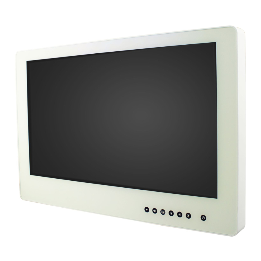
1.1 Introduction ® UMT-7211 is a 21.5” medical touch panel PC based on the Intel Gen. Core™ processor. It features IP65 ingress protection for the front bezel and can be operated at ambient operating temperature ranging from 0°C to 40°C. -
Page 11: Specifications
IP65 rated front bezel / IP54 (except I/O side) Protection RoHS Certificate CE, FCC Class B, LVD Display & Touchscreen Display Type 21.5” TFT LCD Touch Type Projected capacitive touch Max. 1920 x 1080 Resolution Luminance 300 cd/m2 Contrast 1000:1 Colors Max. 16.7M UMT-7211 User Manual... - Page 12 1 x PCIe (x4) Environment Operating: 0°C ~ 40°C (32 ~ 104 °F) Temperature Storage: --20°C ~ 60°C (-4 ~ 140 °F) Relative 10 ~ 95% (non-condensing) Humidity All specifications are subject to change without prior notice. UMT-7211 User Manual...
-
Page 13: Overview
This button only functions with our optional LED reading light. [B]: Press this button to disable or enable the touchscreen input when you need to clean the surface of the panel. Rear View Oblique View I/O Cover (Optional) UMT-7211 User Manual... -
Page 14: Dimensions
I/O View Name Name Expansion Card Slot COM2 RS-232 USB 2.0 Port COM1 RS-232/422/485 Port USB 3.0 Port System Ground LAN Port (GbE) AC Inlet DisplayPort 1.7 Dimensions Unit: mm UMT-7211 User Manual... -
Page 15: Chapter 2 Hardware Configuration
Chapter 2 Hardware Configuration The information provided in this chapter includes: Memory installation and membrane keypad extension Information and locations of connectors... -
Page 16: Installations
2. Insert the module slantwise and gently push the module straight down until the clips of the slot close to hold the module in place when the module touches the bottom of the slot. To remove the module, press the clips outwards with both hands. UMT-7211 User Manual... -
Page 17: Ssd Replacement
(Insert the M.2 card in the same way.) 2. Push the card down and fix it with the supplied flat head screw. (Fix the M.2 card with a round head screw.) Mini-PCIe: M.2: UMT-7211 User Manual... -
Page 18: Vesa Mounting Installation
2.1.5 VESA Mounting Installation You will need to prepare the VESA mount bracket in advance. Tighten 4 screws as shown below to attach the mounting brackets to the system. UMT-7211 User Manual... -
Page 19: Pin Out For Com1 & Com2
DCD, Data carrier detect DSR, Data set ready RXD, Receive data RTS, Request to send TXD, Transmit data CTS, Clear to send DTR, Data terminal ready RI, Ring indicator Ground Signal Name RS-232 RS-422 RS-485 DATA- DATA+ Ground Ground Ground UMT-7211 User Manual... - Page 20 COM2 RS-232 Port Signal Name Signal Name DCD, Data carrier detect DSR, Data set ready RXD, Receive data RTS, Request to send TXD, Transmit data CTS, Clear to send DTR, Data terminal ready RI, Ring indicator Ground UMT-7211 User Manual...
-
Page 21: Setting The Jumpers
1 2 3 When two pins of a jumper are encased in a jumper cap, this jumper is closed, i.e. turned On. When a jumper cap is removed from two jumper pins, this jumper is open, i.e. turned Off. UMT-7211 User Manual... -
Page 22: Jumper & Connector Locations
2.4 Jumper & Connector Locations Motherboard: MBM7001 UMT-7211 User Manual... -
Page 23: Jumpers Quick Reference
Connector Name Page VDD Power Selection for eDP LVDS Panel Power Selection Clearing CMOS Data Clearing ME Register Factory Use Only JP1, JP2, JP5 2.5.1 VDD Power Selection for eDP (JP3) Function Pin closed Illustration 3.3V (default) UMT-7211 User Manual... -
Page 24: Lvds Panel Power Selection (Jp6)
2.5.2 LVDS Panel Power Selection (JP6) Function Pin closed Illustration 3.3V (default) 2.5.3 Clearing CMOS Data Register (JP7) Function Pin closed Illustration Normal (default) Clear CMOS UMT-7211 User Manual... -
Page 25: Clearing Me Register Selection (Jp8)
Hardware Configuration 2.5.4 Clearing ME Register Selection (JP8) Function Pin closed Illustration Normal (default) Clear ME Register UMT-7211 User Manual... -
Page 26: Connectors Quick Reference
CN3 (COM2 RS-232), Isolated COM Ports CN4 (COM1 RS-232/422/485) USB 3.0 Ports USB 2.0 Ports GbE LAN Port CN8, CN9 DisplayPort CN10 Factory Use Only J11, J14, J17, J24 [1]: Refer to 2.2 Pin out for COM1 & COM2 UMT-7211 User Manual... -
Page 27: Amplifier Connector (J2)
Hardware Configuration 2.6.1 Amplifier Connector (J2) Signal Name Signal Name OUTL+ OUTR- OUTL- OUTR+ 2.6.2 Audio Connector (J1) Signal Name Signal Name Lineout_L Lineout_R JD_FRONT Ground LINEIN_L Linein_R JD_LINEIN Ground MIC_L MIC-R JD_MIC1 Ground UMT-7211 User Manual... -
Page 28: Com3 Rs-232 Port (J3)
Data terminal ready Ground DSR, Data set ready RTS, Request to send CTS, Clear to send RI, Ring indicator Not Used 2.6.4 Backlight Connector (J22) Signal Name Signal Name +12V Backlight Enable +12V Brightness Control Ground +3.3V Ground UMT-7211 User Manual... -
Page 29: Lvds Connector (J21, J25)
Hardware Configuration 2.6.5 LVDS Connector (J21, J25) J21: J25: Signal Name Signal Name TX0P TX0N Ground Ground TX1P TX1N Ground Ground TX2P TX2N Ground Ground CLKP CLKN Ground Ground TX3P TX3N Power Power UMT-7211 User Manual... -
Page 30: Edp Connector (Cn2)
2.6.6 eDP Connector (CN2) Signal Name Signal Name Ground VDD_EDP (JP3 SEL +3.3V or +5V) VDD_EDP (JP3 SEL +3.3V or +5V) Ground AUXN AUXP Brightness BKLT_EN TXP0 Ground TXN0 Ground Ground Ground TXP1 Ground TXN1 Ground Ground UMT-7211 User Manual... -
Page 31: Chapter 3 Driver Installation
Chapter 3 Driver Installation The information provided in this chapter includes: ® Intel Chipset Software Installation Utility Graphics Driver Installation HD Audio Driver Installation ® Intel PRO LAN Network Drivers Installation ® Intel ME 11.x Drivers Installation... -
Page 32: Introduction
INF files for Plug & Play function for the chipset components. Follow the instructions below to complete the installation. 1. Insert the disk enclosed in the package. Click Intel and then Intel(R) Skylake-U/Kabylake-U Chipset Drivers. 2. Click Intel(R) Chipset Software Installation Utility. UMT-7211 User Manual... - Page 33 5. Read the Readme File Information, and then click Install. 6. Choose a destination folder for installation. 7. The driver has been completely installed. Click Finish, and restart the computer for changes to take effect. UMT-7211 User Manual...
-
Page 34: Graphics Driver Installation
3.3 Graphics Driver Installation 1. Click Intel, and then Intel(R) Skylake-U/Kabylake-U Chipset Drivers. 2. Click Intel(R) HD Graphics Driver. 3. When the Welcome screen appears, click Next to continue. UMT-7211 User Manual... - Page 35 4. Click Yes to agree with the license agreement, and continue the installation. 5. Read the Readme File Information, and then click Next. 6. Choose a destination folder for installation. 7. The driver has been completely installed. Click Finish, and restart the computer for changes to take effect. UMT-7211 User Manual...
-
Page 36: Hd Audio Driver Installation
3.4 HD Audio Driver Installation 1. Click Intel and then Intel(R) Skylake-U/Kabylake-U Chipset Drivers. 2. Click Realtek High Definition Audio Driver. 3. On the Welcome screen of the InstallShield Wizard, click Next. UMT-7211 User Manual... - Page 37 4. The screenshot shows the description of setup options. Click Next. 5. Choose a destination folder for installation. 6. The driver has been completely installed. Click Finish, and restart the computer and for changes to take effect. UMT-7211 User Manual...
-
Page 38: Lan Network Driver Installation
3.5 LAN Network Driver Installation 1. Click Intel and then Intel(R) Skylake-U/Kabylake-U Chipset Drivers. 2. Click Intel(R) PRO LAN Network Drivers. 3. On the Welcome screen of the InstallShield Wizard, click Next. UMT-7211 User Manual... - Page 39 5. On the Setup Options screen, select the desired drivers, and click Next and then Install. 6. Choose a destination folder for installation. 7. The driver has been completely installed. Click Finish, and restart the computer for changes to take effect. UMT-7211 User Manual...
-
Page 40: Intel Management Engine Driver Installation
® 3.6 Intel Management Engine Driver Installation 1. Click Intel and then Intel(R) Skylake-U/Kabylake-U Chipset Drivers. 2. Click Intel(R) ME 11.x Drivers. 3. When the Welcome screen appears, click Next to continue. UMT-7211 User Manual... - Page 41 Driver Installation 4. Accept the licence agreement, and click Next to continue. 5. Choose a destination folder for installation. 6. The driver has been completely installed. Restart the computer for changes to take effect. UMT-7211 User Manual...
-
Page 42: Chapter 4 Bios Setup
Chapter 4 BIOS Setup This chapter describes the different settings available in the AMI BIOS that comes with the board. The topics covered in this chapter are as follows: Main Settings Advanced Settings Chipset Settings Security Settings ... -
Page 43: Introduction
BIOS Setup for UMT-7211 Avoid changing the default settings: We strongly suggest you contact IBASE for technical support before you make any changes in BIOS. Please be noted that the device may malfunction if you change the BIOS settings improperly. -
Page 44: Main Settings
4.3 Main Settings BIOS Setting Description System Date Sets the date. Use the <Tab> key to switch between the data elements. System Time Set the time. Use the <Tab> key to switch between the data elements. UMT-7211 User Manual... -
Page 45: Advanced Settings
BIOS Setup for UMT-7211 4.4 Advanced Settings This section allows you to configure, improve your system and allows you to set up some system features according to your preference. 4.4.1 LED Backlight Control UMT-7211 User Manual... -
Page 46: Acpi Settings
4.4.2 ACPI Settings BIOS Setting Description Enable Hibernation Enables / Disables the system ability to hibernate (OS/S4 Sleep State). This option may not be effective with some OS. UMT-7211 User Manual... -
Page 47: Amt Configuration
BIOS Setup for UMT-7211 4.4.3 AMT Configuration BIOS Setting Description Intel AMT Enables / Disables Intel(R) Active Management Tecnology BIOS Extension. Note: iAMT H/W is alwas enabled. This option just controls the BIOS extension execution. If enabled, this requires additional firmware in the SPI device. -
Page 48: F81846 Super Io Configuration
4.4.4 F81846 Super IO Configuration BIOS Setting Description Serial Ports Configuration Sets parameters of serial ports. Enables / Disables the serial port and select an optimal setting for the Super IO device. 4.4.4.1. Serial Port 1 Configuration UMT-7211 User Manual... -
Page 49: Hardware Monitor
BIOS Setup for UMT-7211 4.4.5 Hardware Monitor BIOS Setting Description CPU Fan smart fan Enables / Disables smart fan control. control Temperatures / Voltages These fields are the parameters of the hardware monitoring function feature of the motherboard. The values are read-only values as monitored by the system and show the PC health status. -
Page 50: Cpu Configuration
Enabling will expose the CPPC v2 interface to allow for hardware controlled P-states. Intel(R) Speed Step (tm) Enables / Disables the function to allow more than two frequency ranges to be supported. Turbo Mode Enables / Disables Turbo Mode. UMT-7211 User Manual... -
Page 51: Sata Configuration
BIOS Setup for UMT-7211 4.4.7 SATA Configuration BIOS Setting Description SATA Controller Enables / Disables SATA device. SATA Mode Selection Selects AHCI Mode. SATA Ports HotPlug Enables / Disables SATA Ports HotPlug. 4.4.8 CSM Configuration BIOS Setting Description Network Controls the execution of UEFI and Legacy PXE OpROM. -
Page 52: Usb Configuration
Maximum time the device will take before it properly reports itself to the host controller. Auto uses default value. For a root port It is 100 ms, and for a hub port the delay is taken from hub descriptor. UMT-7211 User Manual... -
Page 53: Appendix
Appendix This section provides the mapping addresses of peripheral devices and the sample code of watchdog timer configuration. I/O Port Address Map Interrupt Request Lines (IRQ) Digital I/O Sample Code Watchdog Timer Configuration... -
Page 54: I/O Port Address Map
Motherboard resources 0x00000A10-0x00000A1F Motherboard resources 0x0000002E-0x0000002F Motherboard resources 0x0000004E-0x0000004F Motherboard resources 0x00000061-0x00000061 Motherboard resources 0x00000063-0x00000063 Motherboard resources 0x00000065-0x00000065 Motherboard resources 0x00000067-0x00000067 Motherboard resources 0x00000070-0x00000070 Motherboard resources 0x00000070-0x00000070 System CMOS/real time clock 0x00000080-0x00000080 Motherboard resources 0x00000092-0x00000092 Motherboard resources UMT-7211 User Manual... - Page 55 Express Root Port #10 - 9D19 0x0000F040-0x0000F05F Intel(R) 100 Series Chipset Family SMBUS - 9D23 0x0000FF00-0x0000FFFE Motherboard resources 0x00000060-0x00000060 Standard PS/2 Keyboard 0x00000064-0x00000064 Standard PS/2 Keyboard 0x0000F090-0x0000F097 Standard SATA AHCI Controller 0x0000F080-0x0000F083 Standard SATA AHCI Controller 0x0000F060-0x0000F07F Standard SATA AHCI Controller UMT-7211 User Manual...
-
Page 56: Interrupt Request Lines (Irq)
Intel(R) I211 Gigabit Network Connection IRQ 4294967292 Intel(R) Ethernet Connection I219-LM IRQ 1 Standard PS/2 Keyboard IRQ 12 Microsoft PS/2 Mouse IRQ 16 High Definition Audio Controller IRQ 4294967293 Standard SATA AHCI Controller IRQ 8 System CMOS/real time clock UMT-7211 User Manual... -
Page 57: Watchdog Timer Configuration
**endptr; char SIO; printf("Fintek 81866 watch dog program\n"); SIO = Init_F81866(); if (SIO == 0) printf("Can not detect Fintek 81866, program abort.\n"); return(1); }//if (SIO == 0) if (argc != 2) printf(" Parameter incorrect!!\n"); return (1); UMT-7211 User Manual... - Page 58 //--------------------------------------------------------------------------- void DisableWDT(void) unsigned char bBuf; Set_F81866_LD(0x07); //switch to logic device 7 bBuf = Get_F81866_Reg(0xFA); bBuf &= ~0x01; Set_F81866_Reg(0xFA, bBuf); //disable WDTO output bBuf = Get_F81866_Reg(0xF5); bBuf &= ~0x20; bBuf |= 0x40; Set_F81866_Reg(0xF5, bBuf); //disable WDT //--------------------------------------------------------------------------- UMT-7211 User Manual...
- Page 59 (ucDid == 0x07) //Fintek 81866 goto Init_Finish; } F81866_BASE = 0x00; result = F81866_BASE; Init_Finish: return (result); //--------------------------------------------------------------------------- void Unlock_F81866 (void) outportb(F81866_INDEX_PORT, F81866_UNLOCK); outportb(F81866_INDEX_PORT, F81866_UNLOCK); //--------------------------------------------------------------------------- void Lock_F81866 (void) outportb(F81866_INDEX_PORT, F81866_LOCK); //--------------------------------------------------------------------------- void Set_F81866_LD( unsigned char LD) UMT-7211 User Manual...
- Page 60 #define F81866_DATA_PORT (F81866_BASE+1) //--------------------------------------------------------------------------- #define F81866_REG_LD 0x07 //--------------------------------------------------------------------------- #define F81866_UNLOCK 0x87 #define F81866_LOCK 0xAA //--------------------------------------------------------------------------- unsigned int Init_F81866(void); void Set_F81866_LD( unsigned char); void Set_F81866_Reg( unsigned char, unsigned char); unsigned char Get_F81866_Reg( unsigned char); //--------------------------------------------------------------------------- #endif // F81866_H UMT-7211 User Manual...
Need help?
Do you have a question about the UMT-7211 and is the answer not in the manual?
Questions and answers