
Related Manuals for IBASE Technology BYTEM-123-PC


Summary of Contents for IBASE Technology BYTEM-123-PC
- Page 1 BYTEM-123-PC Industrial Panel PC for Railway User’s Manual Version 1.0 (December 2020)
- Page 2 No part of this publication may be reproduced, copied, stored in a retrieval system, translated into any language or transmitted in any form or by any means, electronic, mechanical, photocopying, or otherwise, without the prior written consent of IBASE Technology, Inc. (hereinafter referred to as “IBASE”).
-
Page 3: Compliance
EU directive of for waste electrical and electronic equipment (WEEE - 2012/19/EU). Instead, it should be disposed of by returning it to a municipal recycling collection point. Check local regulations for disposal of electronic products. BYTEM-123-PC User Manual... -
Page 4: Important Safety Information
You are not suggested to disassemble, repair or make any modification to the device. Disassembly, modification, or any attempt at repair could generate hazards and cause damage to the device, even bodily injury or property damage, and will void any warranty. Attention during use: BYTEM-123-PC User Manual... -
Page 5: Warranty Policy
IBASE, such as CPU, CPU cooler, memory, storage devices, power adapter, panel and touchscreen. * Products, however, that fail due to misuse, accident, improper installation or unauthorized repair shall be treated as out of warranty and customers shall be billed for repair and shipping charges. BYTEM-123-PC User Manual... -
Page 6: Technical Support & Services
Software in use (such as OS and application software, including the version numbers) 3. If repair service is required, you can download the RMA form at http://www.ibase.com.tw/english/Supports/RMAService/. Fill out the form and contact your distributor or sales representative. BYTEM-123-PC User Manual... -
Page 7: Table Of Contents
LED Indicators for Power and HDD (LED1) ......23 2.5.3 SATA II / mSATA Port (CN1) ..........23 2.5.4 SATA II Port (CN2)............... 24 2.5.5 USB 3.0 Port (CN3) .............. 24 2.5.6 LAN Port (GbE) (CN4, CN5) ..........24 BYTEM-123-PC User Manual... - Page 8 LVDS Configuration ..............46 4.4.3 iSMART Controller ..............47 4.4.4 Super IO Configuration ............48 4.4.5 Hardware Monitor ..............49 4.4.6 CPU Configuration ..............50 4.4.7 CPU PPM Configuration ............51 4.4.8 IDE Configuration ..............52 viii BYTEM-123-PC User Manual...
- Page 9 Security Settings ................... 56 Boot Settings..................57 Save & Exit Settings................58 Appendix ...................... 59 I/O Port Address Map ................60 Interrupt Request Lines (IRQ) ............... 61 Digital I/O Sample Code ................ 62 Watchdog Timer Configuration .............. 67 BYTEM-123-PC User Manual...
-
Page 11: Chapter 1 General Information
Chapter 1 General Information The information provided in this chapter includes: Features Packing List Specifications Overview Dimensions... -
Page 12: Introduction
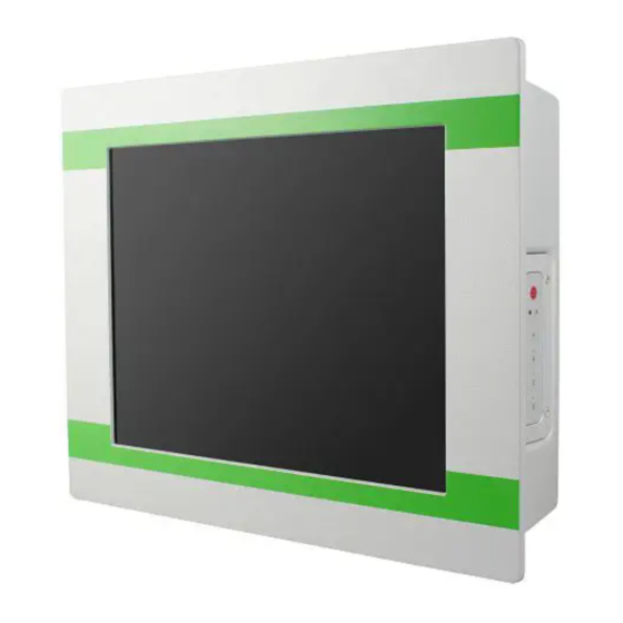
1.1 Introduction BYTEM-123-PC is a 12.1” industrial projected touch panel PC that is railway Atom™ E3845 Quad-Core based processor, the device ® compliant. With Intel carries the level of IP65 ingress protection for the panel to provide good quality of water-tight. The readability is especially enhanced for operating on rolling shock on the railway. -
Page 13: Packing List
General Information 1.3 Packing List Your BYTEM-123-PC package should include the items listed below. If any of the items below is missing, contact the distributor or the dealer from whom you purchased the product. BYTEM-123-PC Keypad Cover ... -
Page 14: Specifications
Dimensions (13.18” x 10.5” x 28.58”) (W x H x D) Net Weight 3.6 kg (7.94 lb) IP65 for front bezel Ingress Protection IP54 for the whole unit with I/O cover Certificate CE, FCC Class B, EN50155 BYTEM-123-PC User Manual... - Page 15 Environment Operating: -40 ~ 70 °C (-40 ~ 158 °F) Temperature Storage: -40 ~ 85 °C (-40 ~ 185 °F) Relative 10 ~ 90% (non-condensing) Humidity All specifications are subject to change without prior notice. BYTEM-123-PC User Manual...
-
Page 16: Overview
1.5 Overview Oblique View No. Name Name Volume Control LED Indicator for Power Brightness Control Power Button LED Indicator for HDD BYTEM-123-PC User Manual... - Page 17 General Information Rear View No. Name Name LAN Port (10/100) Additional Rack Mount Kit Power Port I/O Cover The Pin definition of external power cable as following: USB 2.0 Port BYTEM-123-PC User Manual...
-
Page 18: Dimensions
I/O View No. Name Name 2.5” Drive Bay LAN Port (GbE) USB 2.0 Port Display Port USB 3.0 Port COM Port 1.6 Dimensions Unit: mm Without Additional Rack Mount Kit BYTEM-123-PC User Manual... - Page 19 General Information With Additional Rack-Mount Kit BYTEM-123-PC User Manual...
-
Page 20: Chapter 2 Hardware Installation & Motherboard Information
Chapter 2 Hardware Installation & Motherboard Information The information provided in this chapter includes: Memory installation and membrane keypad extension Information and locations of connectors... -
Page 21: Hardware Installation
You can extend the membrane keypad with the supplied extension cable. Follow the steps below to install the extension cable. Release 4 screws of the membrane keypad and pull out the cable. Separate the connected flat cables and secure the supplied keypad cover. Keypad Cover BYTEM-123-PC User Manual... - Page 22 Extend the keypad with the supplied extension cable. A. Connect the female end of the extension cable to the cable protruding from the device by aligning the pin 1 to pin 1 (white dots). BYTEM-123-PC User Manual...
- Page 23 1 to pin 1 (white dot on the extension cable to the arrow on the flat cable of the membrane keypad). The membrane Keypad is now extended. If you need to secure the extended keypad, you will need to prepare 4 screws (M3) yourself. BYTEM-123-PC User Manual...
-
Page 24: Memory Installation
2.1.2 Memory Installation There are two SO-DIMM DDR3L memory slots inside BYTEM-123-PC and the maximum memory supported is 8 GB. The BYTEM-123-PC supports two SO- DIMM DDR3L memory slots for a maximum total memory of 8GB. To install the modules, locate the memory... -
Page 25: Vesa Mount & Wall Mount Installation
Tighten 4 screws as below to attach the device to the bracket. 2. Wall Mount Tighten the supplied M3 screws (8 pcs) to secure the Rack Mount Kit. Then install the device to wall with the supplied M4 screws (6 pcs). BYTEM-123-PC User Manual... -
Page 26: Setting The Jumpers
2.2 Setting the Jumpers Set up and configure your BYTEM-123-PC by using jumpers for various settings and features according to your needs and applications. Contact your supplier if you have doubts about the best configuration for your use. 2.2.1 How to Set Jumpers Jumpers are short-length conductors consisting of several metal pins with a non-conductive base mounted on the circuit board. -
Page 27: Jumper & Connector Locations On Motherboard
Motherboard Information 2.3 Jumper & Connector Locations on Motherboard Motherboard: IB897 LED1 SYS_FAN1 IB897 - top BYTEM-123-PC User Manual... - Page 28 Intel ® Atom™ E3845 Quad-Core IB897 - bottom BYTEM-123-PC User Manual...
-
Page 29: Jumpers Quick Reference
Motherboard Information 2.4 Jumpers Quick Reference Function Connector Name Page LVDS Panel Power Selection LVDS Panel Brightness Control Selection ME Register Clearance CMOS Data Clearance 2.4.1 LVDS Panel Power Selection (J5) Function Pin closed Illustration 3.3V (default) BYTEM-123-PC User Manual... -
Page 30: Lvds Panel Brightness Control Selection (Jp2)
2.4.2 LVDS Panel Brightness Control Selection (JP2) Function Pin closed Illustration 3.3V Open Close (default) 2.4.3 ME Register Clearance (JP5) Function Pin closed Illustration Normal (default) Clear ME Register BYTEM-123-PC User Manual... -
Page 31: Cmos Data Clearance (Jp6)
Motherboard Information 2.4.4 CMOS Data Clearance (JP6) Function Pin closed Illustration Normal (default) Clear CMOS BYTEM-123-PC User Manual... -
Page 32: Connectors Quick Reference
Full-Sized Mini-PCIe / mSATA Connector Half-Sized Mini-PCIe Connector USB 2.0 Connector COM2 (RS-232) Port VGA Port Digital I/O Connector Motherboard Power Input Connector Reset Switch Connector Power Switch Connector LCD Backlight Connector System Fan Power Connector SYS_FAN1 BYTEM-123-PC User Manual... -
Page 33: Motherboard Power Button (Sw1)
Motherboard Information 2.5.1 Motherboard Power Button (SW1) 2.5.2 LED Indicators for Power and HDD (LED1) The green LED is Power LED. The red LED is HDD LED. 2.5.3 SATA II / mSATA Port (CN1) BYTEM-123-PC User Manual... -
Page 34: Sata Ii Port (Cn2)
2.5.4 SATA II Port (CN2) 2.5.5 USB 3.0 Port (CN3) 2.5.6 LAN Port (GbE) (CN4, CN5) BYTEM-123-PC User Manual... -
Page 35: Usb 2.0 Port (Cn6)
Motherboard Information 2.5.7 USB 2.0 Port (CN6) 2.5.8 Display Port (CN7) BYTEM-123-PC User Manual... -
Page 36: Com1 Port (Rs-232/422/485) (Cn8)
DCD, Data carrier detect DSR, Data set ready RXD, Receive data RTS, Request to send TXD, Transmit data CTS, Clear to send DTR, Data terminal ready RI, Ring indicator GND, ground Assignment RS-232 RS-422 RS-485 DATA- DATA+ Ground Ground Ground BYTEM-123-PC User Manual... -
Page 37: Audio Connector (J1)
Motherboard Information 2.5.10 Audio Connector (J1) COM1 port is jumper-less and configurable on BIOS. Assigment Assigment Lineout_L JD_LINEIN Lineout_R Ground JD_FRONT MIC_L Ground MIC-R LINEIN_L JD_MIC1 Linein_R Ground 2.5.11 Amplifier Connector (J2) Assigment OUTL+ OUTL- OUTR- OUTR+ BYTEM-123-PC User Manual... -
Page 38: Ddr3L So-Dimm Socket (J3, J7)
Channel B up the board. 2.5.13 LVDS Connector (J4, J6) J6: Channel 1 J4: Channel 2 Assigment Assigment TX0P Ground TX0N Ground Ground CLKP Ground CLKN TX1P Ground TX1N Ground Ground TX3P Ground TX3N TX2P Power TX2N Power(1A) BYTEM-123-PC User Manual... -
Page 39: Sata Hdd Power Connector (J10)
Motherboard Information 2.5.14 SATA HDD Power Connector (J10) Assigment +5V(1A) Ground Ground +12V(1A) 2.5.15 Smart Battery Connector (J11) Assigment RST# ICHSWI# Ground SMB_DATA SMB_CLK BYTEM-123-PC User Manual... -
Page 40: Full-Sized Mini-Pcie / Msata Connector (J12)
2.5.16 Full-Sized Mini-PCIe / mSATA Connector (J12) 2.5.17 Half-Sized Mini-PCIe Connector (J13) 2.5.18 USB 2.0 Connector (J14) Assigment Assigment Ground Ground BYTEM-123-PC User Manual... -
Page 41: Com2 (Rs-232) Port (J15)
RXD, Receive data RTS, Request to send TXD, Transmit data CTS, Clear to send Data terminal ready RI, Ring indicator GND, ground Not Used 2.5.20 VGA Port (J16) Assigment Assigment H_SYNC Green Ground V_SYNC Blue DDCCLK DDCDATA N.C. BYTEM-123-PC User Manual... -
Page 42: Digital I/O Connector (J17)
2.5.21 Digital I/O Connector (J17) Assigment Assigment OUT0 VCC(500mA) OUT3 OUT1 OUT2 2.5.22 Motherboard Power Input Connector (J18) Assigment +9V to +30V(10A) BYTEM-123-PC User Manual... -
Page 43: Reset Switch Connector (J19)
Motherboard Information 2.5.23 Reset Switch Connector (J19) Assigment Reset Switch Ground 2.5.24 Power Switch Connector (J20) Assigment Power Switch Ground BYTEM-123-PC User Manual... -
Page 44: Lcd Backlight Connector (Jp3)
2.5.25 LCD Backlight Connector (JP3) Assigment +12V(1A) Backlight Enable Brightness Control Ground 2.5.26 System Fan Power Connector (SYS_FAN1) Assigment Ground +12V(500mA) Rotation detection BYTEM-123-PC User Manual... -
Page 45: Chapter 3 Driver Installation
Chapter 3 Driver Installation The information provided in this chapter includes: ® Intel Chipset Software Installation Utility VGA Driver Installation HD Audio Driver Installation ® Intel Trusted Execution Engine Installation LAN Driver Installation... -
Page 46: Introduction
If you find anything missing, please contact the distributor where you made the purchase. Note: After installing your Windows operating system, you must install the ® Intel Chipset Software Installation Utility first before proceeding with the drivers installation. BYTEM-123-PC User Manual... -
Page 47: Intel Chipset Software Installation Utility
Chipset Device Software appears, click Next to continue. Click Yes to accept the software license agreement and proceed with the installation process. The driver has been completely installed. Click Finish to restart the computer and for changes to take effect. BYTEM-123-PC User Manual... -
Page 48: Vga Driver Installation
When the Welcome screen appears, click Next to continue. Click Yes to agree with the license agreement and continue the installation. The driver has been completely installed. Click Finish to restart the computer and for changes to take effect. BYTEM-123-PC User Manual... -
Page 49: Hd Audio Driver Installation
Intel(R) Baytrail Chipset Drivers. Click Realtek High Definition Audio Driver. On the Welcome screen of the InstallShield Wizard, click Next for installation. The driver has been completely installed. Click Finish to restart the computer and for changes to take effect. BYTEM-123-PC User Manual... -
Page 50: Intel Trusted Execution Engine Installation
Click Intel and then Intel(R) TXE Drivers. When the Weocome screen appears, click Next to contiune installation. Click Next to agree with the license agreement and continue the installation. The driver has been completely installed. Click Finish. BYTEM-123-PC User Manual... -
Page 51: Chapter 4 Bios Setup
Chapter 4 BIOS Setup This chapter the different settings available in the AMI describes BIOS that comes with the board. The topics covered in this chapter are as follows: Main Settings Advanced Settings Chipset Settings Security Settings ... -
Page 52: Introduction
These defaults have been carefully chosen by both AMI and your system manufacturer to provide the absolute maximum performance and reliability. Changing the defaults could make the system unstable and crash in some cases. BYTEM-123-PC User Manual... -
Page 53: Main Settings
System Language Choose the system default laugage System Date Sets the date. Use the <Tab> key to switch between the data elements. System Time Set the time. Use the <Tab> key to switch between the data elements. BYTEM-123-PC User Manual... -
Page 54: Advanced Settings
4.4 Advanced Settings This section allows you to configure, improve your system and allows you to set up some system features according to your preference. BYTEM-123-PC User Manual... -
Page 55: Acpi Settings
Enables or disables the System ability to Hibernate (OS/S4 Sleep State). This option may not be effective with some OS. ACPI Sleep State Selects ACPI sleep state that the system will enter when the suspend button is pressed. BYTEM-123-PC User Manual... -
Page 56: Lvds Configuration
4.4.2 LVDS Configuration BYTEM-123-PC User Manual... -
Page 57: Ismart Controller
Controller BIOS Setting Description Power-On after Power Enables / Disables the system to be turned on failure automatically after a power failure. Schedule Slot 1 / 2 Sets up the hour / minute for system powe-on. BYTEM-123-PC User Manual... -
Page 58: Super Io Configuration
4.4.4 Super IO Configuration BIOS Setting Description Serial Port 1 Configuration Sets parameters of serial port 1 (COMA). Serial Port 2 Configuration Sets parameters of serial port 2 (COMA). BYTEM-123-PC User Manual... -
Page 59: Hardware Monitor
80 °C, 85 °C, 90 °C, 95 °C Temperatures / Voltages These fields are the parameters of the hardware monitoring function feature of the motherboard. The values are read-only values as monitored by the system and show the PC health status BYTEM-123-PC User Manual... -
Page 60: Cpu Configuration
4.4.6 CPU Configuration BIOS Setting Description Socket 0 CPU Information Displays the specific socket CPU Information. BYTEM-123-PC User Manual... -
Page 61: Cpu Ppm Configuration
BIOS Setup 4.4.7 CPU PPM Configuration BIOS Setting Description EIST Enables or disables Intel SpeedStep. BYTEM-123-PC User Manual... -
Page 62: Ide Configuration
Serial –ATA Port 0 Enables / Disables Serial Port 0. SATA Port0 HotPlug Enables / Disables SATA Port 0 HotPlug. Serial –ATA Port 1 Enables / Disables Serial Port 1. SATA Port1 HotPlug Enables / Disables SATA Port 1 HotPlug. BYTEM-123-PC User Manual... -
Page 63: Sdio Configuration
SDIO Access Mode Auto: Access an SD device in DMA mode if controller supports it. Otherwise, in PIO mode. DMA: Access an SD device in DMA mode. PIO: Access an PIO device in DMA mode. BYTEM-123-PC User Manual... -
Page 64: Usb Configuration
4.4.10 USB Configuration BIOS Setting Description Legacy USB Support Enable: Enables Ledacy USB Support. Auto: Disables legacy support if no USB devices are connected. Disable: Keeps USB devices available only for EFI applications. BYTEM-123-PC User Manual... -
Page 65: Chipset Settings
BIOS Setup 4.5 Chipset Settings 4.5.1 North Bridge BYTEM-123-PC User Manual... -
Page 66: Security Settings
This section allows you to configure, improve your system, and set up some system features according to your preference. BIOS Setting Description Administrator Password Sets an administrator password for the setup utility. User Password Sets a user password. BYTEM-123-PC User Manual... -
Page 67: Boot Settings
Enables / Disables Quiet Boot option. Fast Boot Enables / Disables boot with initialization of a minimal set of devices required to launch the active boot option. There no effect for BBS boot options. Boot Option Priorities Sets the system boot order. BYTEM-123-PC User Manual... -
Page 68: Save & Exit Settings
Restore Defaults Restores / Loads defaults values for all the setup options. Save as User Defaults Saves the changes done so far as user defaults. Restore User Defaults Restores the user defaults to all the setup options. BYTEM-123-PC User Manual... -
Page 69: Appendix
Appendix This section provides the mapping addresses of peripheral devices and the sample code of watchdog timer configuration. I/O Port Address Map Interrupt Request Lines (IRQ) Digital I/O Sample Code Watchdog Timer Configuration... -
Page 70: I/O Port Address Map
Intel(R) 8 Series/C220 Series SATA AHCI Controller - 8C02 F0C0h-F0C3h Intel(R) 8 Series/C220 Series SATA AHCI Controller - 8C02 F0D0h-F0D7h Intel(R) 8 Series/C220 Series SATA AHCI Controller - 8C02 F0E0h-F0E7h Intel(R) Active Management Technology - SOL (COM3) BYTEM-123-PC User Manual... -
Page 71: Interrupt Request Lines (Irq)
IRQ 19 Intel(R) 8 Series/C220 Series SATA AHCI Controller - 8C02 IRQ 19 Intel(R) Active Management Technology - SOL (COM3) IRQ 22 High Definition Audio Controller IRQ 23 Intel(R) 8 Series/C220 Series USB EHCI #1 - 8C26 BYTEM-123-PC User Manual... -
Page 72: Digital I/O Sample Code
(NCT5523D_BASE) #define NCT5523D_DATA_PORT (NCT5523D_BASE+1) //--------------------------------------------------------------------------- #define NCT5523D_REG_LD 0x07 //--------------------------------------------------------------------------- #define NCT5523D_UNLOCK 0x87 #define NCT5523D_LOCK 0xAA //--------------------------------------------------------------------------- unsigned int Init_NCT5523D(void); void Set_NCT5523D_LD( unsigned char); void Set_NCT5523D_Reg( unsigned char, unsigned char); unsigned char Get_NCT5523D_Reg( unsigned char); //--------------------------------------------------------------------------- #endif //__NCT5523D_H BYTEM-123-PC User Manual... - Page 73 Nuvoton NCT5523D, program abort.\n"); return(1); Dio5Initial(); //for GPIO20..27 Dio5SetDirection(0x0F); //GP20..23 = input, GP24..27=output printf("Current DIO direction = 0x%X\n", Dio5GetDirection()); printf("Current DIO status = 0x%X\n", Dio5GetInput()); printf("Set DIO output to high\n"); Dio5SetOutput(0x0F); printf("Set DIO output to low\n"); Dio5SetOutput(0x00); return 0; //--------------------------------------------------------------------------- BYTEM-123-PC User Manual...
- Page 74 Dio5SetDirection(unsigned char NewData) //NewData : 1 for input, 0 for output Set_NCT5523D_LD(0x07); //switch to logic device 7 Set_NCT5523D_Reg(0xE8, NewData); //--------------------------------------------------------------------------- unsigned char Dio5GetDirection(void) unsigned char result; Set_NCT5523D_LD(0x07); //switch to logic device 7 result = Get_NCT5523D_Reg(0xE8); return (result); //--------------------------------------------------------------------------- BYTEM-123-PC User Manual...
- Page 75 = NCT5523D_BASE; ucDid = Get_NCT5523D_Reg(0x20); if (ucDid == 0xC4) //NCT5523D?? goto Init_Finish; } NCT5523D_BASE = 0x00; result = NCT5523D_BASE; Init_Finish: return (result); //--------------------------------------------------------------------------- void Unlock_NCT5523D (void) outportb(NCT5523D_INDEX_PORT, NCT5523D_UNLOCK); outportb(NCT5523D_INDEX_PORT, NCT5523D_UNLOCK); //--------------------------------------------------------------------------- void Lock_NCT5523D (void) outportb(NCT5523D_INDEX_PORT, NCT5523D_LOCK); //--------------------------------------------------------------------------- BYTEM-123-PC User Manual...
- Page 76 LD); Lock_NCT5523D(); //--------------------------------------------------------------------------- void Set_NCT5523D_Reg( unsigned char REG, unsigned char DATA) Unlock_NCT5523D(); outportb(NCT5523D_INDEX_PORT, REG); outportb(NCT5523D_DATA_PORT, DATA); Lock_NCT5523D(); //--------------------------------------------------------------------------- unsigned char Get_NCT5523D_Reg(unsigned char REG) unsigned char Result; Unlock_NCT5523D(); outportb(NCT5523D_INDEX_PORT, REG); Result = inportb(NCT5523D_DATA_PORT); Lock_NCT5523D(); return Result; //--------------------------------------------------------------------------- BYTEM-123-PC User Manual...
-
Page 77: Watchdog Timer Configuration
(NCT5523D_BASE) #define NCT5523D_DATA_PORT (NCT5523D_BASE+1) //--------------------------------------------------------------------------- #define NCT5523D_REG_LD 0x07 //--------------------------------------------------------------------------- #define NCT5523D_UNLOCK 0x87 #define NCT5523D_LOCK 0xAA //--------------------------------------------------------------------------- unsigned int Init_NCT5523D(void); void Set_NCT5523D_LD( unsigned char); void Set_NCT5523D_Reg( unsigned char, unsigned char); unsigned char Get_NCT5523D_Reg( unsigned char); //--------------------------------------------------------------------------- #endif //__NCT5523D_H BYTEM-123-PC User Manual... - Page 78 (SIO == 0) printf("Can not detect Nuvoton NCT5523D, program abort.\n"); return(1); WDTInitial(); WDTEnable(10); WDTDisable(); return 0; //--------------------------------------------------------------------------- void WDTInitial(void) unsigned char bBuf; Set_NCT5523D_LD(0x08); //switch to logic device 8 bBuf = Get_NCT5523D_Reg(0x30); bBuf &= (~0x01); Set_NCT5523D_Reg(0x30, bBuf); //Enable WDTO //--------------------------------------------------------------------------- BYTEM-123-PC User Manual...
- Page 79 //enable timer bBuf = Get_NCT5523D_Reg(0xF0); bBuf &= (~0x08); Set_NCT5523D_Reg(0xF0, bBuf); //count mode is second Set_NCT5523D_Reg(0xF1, NewInterval); //set timer //--------------------------------------------------------------------------- void WDTDisable(void) Set_NCT5523D_LD(0x08); //switch to logic device 8 Set_NCT5523D_Reg(0xF1, 0x00); //clear watchdog timer Set_NCT5523D_Reg(0x30, 0x00); //watchdog disabled //--------------------------------------------------------------------------- BYTEM-123-PC User Manual...
- Page 80 Init_Finish; } NCT5523D_BASE = 0x2E; result = NCT5523D_BASE; ucDid = Get_NCT5523D_Reg(0x20); if (ucDid == 0xC4) //NCT5523D?? goto Init_Finish; } NCT5523D_BASE = 0x00; result = NCT5523D_BASE; Init_Finish: return (result); //--------------------------------------------------------------------------- void Unlock_NCT5523D (void) outportb(NCT5523D_INDEX_PORT, NCT5523D_UNLOCK); outportb(NCT5523D_INDEX_PORT, NCT5523D_UNLOCK); //--------------------------------------------------------------------------- BYTEM-123-PC User Manual...
- Page 81 LD); Lock_NCT5523D(); //--------------------------------------------------------------------------- void Set_NCT5523D_Reg( unsigned char REG, unsigned char DATA) Unlock_NCT5523D(); outportb(NCT5523D_INDEX_PORT, REG); outportb(NCT5523D_DATA_PORT, DATA); Lock_NCT5523D(); //--------------------------------------------------------------------------- unsigned char Get_NCT5523D_Reg(unsigned char REG) unsigned char Result; Unlock_NCT5523D(); outportb(NCT5523D_INDEX_PORT, REG); Result = inportb(NCT5523D_DATA_PORT); Lock_NCT5523D(); return Result; //----------------------------------------------------------------------- BYTEM-123-PC User Manual...
Need help?
Do you have a question about the BYTEM-123-PC and is the answer not in the manual?
Questions and answers