Table of Contents
Advertisement
Quick Links
Advertisement
Table of Contents

Related Manuals for Esaote MyLabX8


Summary of Contents for Esaote MyLabX8
- Page 1 Rev. 08 February 2020 MyLabX8 MyLabX8 eXP GETTING STARTED 350031600...
-
Page 3: Manufacturer's Address
MyLabX8 eXP For US Customers: US Federal Law restricts this device to sale, distribution and use by or on the order of a physician. All information included in this manual is relative to the following Esaote ultrasound equipments: MyLabX8 MyLabX8 eXP... -
Page 4: Guarantee
Guarantee The information in this document is the exclusive property of Esaote S.p.A. and is reserved. Reproduction or distribution in any form is strictly prohibited. All rights reserved. All screenshots, pictures and graphics in this manual are used for descriptive purposes only and may be different from what you see on the screen or device. -
Page 5: Ec Declaration Of Conformity
EC Declaration of Conformity MyLab - G E T T I N G S T A R T E D... - Page 6 MyLab - G E T T I N G S T A R T E D...
-
Page 7: Red Declaration Of Conformity
RED Declaration of Conformity MyLab - G E T T I N G S T A R T E D... - Page 8 MyLab - G E T T I N G S T A R T E D viii...
- Page 9 MyLab - G E T T I N G S T A R T E D...
- Page 10 MyLab - G E T T I N G S T A R T E D...
-
Page 11: Table Of Contents
I N D E X Table of Contents Manufacturer’s Address ................i-iii Important Information ................i-iii Guarantee..................... i-iv Trade Marks....................i-iv EC Declaration of Conformity..............i-v RED Declaration of Conformity ............i-vii 1 Introduction.................. 1-1 Safety and Standards................1-1 Getting Started ................... 1-1 Probes and Consumables.............. - Page 12 I N D E X Communication Systems and MyLab..........2-6 Wireless Requirements ................2-7 3 System Overview ................3-1 About the system..................3-1 Intended Use.....................3-1 Clinical Applications and Supporting Probes ........3-2 Patient population..................3-4 Operator profile ..................3-4 Contraindications ..................3-4 System Components ...................3-5 Monitor (1)....................3-6 On/Off Button (2) ..................3-7 Control Panel Assembly (4)..............3-8 Control Panel Assembly Orientation..........3-9 Pull-out Qwerty Keyboard (12) ............3-10...
- Page 13 I N D E X Turning the System On and Off .............. 5-1 System Controls ..................5-2 Control Panel Section ................5-2 TGC Sliding ..................5-4 Trackball ....................5-5 Joystick....................5-5 Touchscreen Section................5-6 Menu Button..................5-6 Touchscreen..................5-6 Alphanumeric Keyboard Section ............5-9 Information about the Screen Layout .............
- Page 14 I N D E X Field SHUTDOWN TYPE ............6-13 Field AVAILABLE QWERTIES ..........6-14 CINE MODE Folder ..............6-14 APPLICATION PRESET Folder..........6-14 FOOTSWITCH Folder..............6-16 PROBE BUTTONS Folder ............6-16 RAW DATA Folder.................6-16 KEYBOARD BUTTONS Folder ..........6-16 Security.....................6-16 Licenses Manager ...................6-16 License Activation ................6-17 Import/Export Menu................6-18 EXPORT Folder ................6-18 IMPORT Folder ................6-19...
- Page 15 I N D E X Licenses..................... 9-1 Technical Characteristics ................9-4 Display....................... 9-4 Probe connectors..................9-5 Connectivity ..................... 9-5 Image Files....................9-5 Software ....................9-5 Biometry....................9-5 Keyboard ....................9-6 Dimensions....................9-6 Weight ....................... 9-6 IP Grade....................9-6 Power supply.................... 9-6 Available power on peripherals............
- Page 16 I N D E X MyLab - G E T T I N G S T A R T E D...
-
Page 17: Introduction
MyLabX8 Family family, or when the contents are common to the other MyLab ultrasound systems belonging to the Esaote platform. MyLab Safety and Standards The Safety and Standard manual contains information about the patient's and operator's safety. -
Page 18: Advanced Operations Manual
NOTE Specifications subject to change without notice. Information might refer to products or modalities not yet approved in all countries. Product images are for illustrative purposes only. For further details, please contact your Esaote sales representative. This manual refers to... -
Page 19: Intended Audience
In case of system failure to operate correctly, the operator should contact the nearest Esaote Service Office. Special attention should be dedicated to intra-cavitary probes (e.g. vaginal, rectal or oesophageal probes). They should be cleaned according to established protocols (AIUM guidelines for cleaning probes) and should not be used if there is noticeable self-heating of the probe when operating in air. -
Page 20: Mylab Use
I N T R O D U C T I O N a part of a more complex diagnostic process that includes medical history, symptoms and other instrumental examinations. A proper patient ID and exact examination date and time must be always included and must appear on all recorded data and prints. -
Page 21: Mylab Manual Conventions
Use of the product for the purposes other than those intended and expressly stated by Esaote, as well as incorrect use or operation, may relieve Esaote or its agents from all or some responsibility for resultant noncompliance, damage, or injury. -
Page 22: Manufacturer's Responsibility
In this manual NOTE points out information of special interest but not NOTE related to risks for patient, operator or device. Manufacturer’s Responsibility Esaote is responsible for the safety, reliability and functioning of this product only if: the user follows all the instructions contained in the system manuals for the use and the maintenance of this system;... -
Page 23: Maintainability Time
You have acquired a device (“ ”) which includes Esaote S.p.A. DEVICE proprietary software and/or software licensed by Esaote S.p.A. from one or more software licensors (“Software Suppliers”). Such software products (“ ”), as well as associated media, printed materials, and “online”... -
Page 24: License Rights And Limitations
For any software updates and/or upgrades installed on the Equipment after installation, the terms herein shall apply in full. License Rights and Limitations With this license, Esaote S.p.A. grants the end user the right to use the on the supplied SOFTWARE... - Page 25 I N T R O D U C T I O N the event of equipment transfer to third parties, are requested to notify ESAOTE S.p.A., associate company or authorized distributor of the said transfer by means of the following form, duly compiled, or written notification with the same data as specified in the form.
-
Page 26: Vigilance System
Esaote central plants, or one of our subsidiaries, or one of our official distributors immediately through the following form, or through a communication reporting the same data contained in this form. - Page 27 I N T R O D U C T I O N POST-MARKET SURVEILLANCE FORM ACCIDENT REPORT FORM To: ESAOTE S.p.A. Quality Assurance Department Via Enrico Melen, 77 16152, Genova, Italy [or associate company] [or authorized distributor] ESAOTE system/device name:................
- Page 28 I N T R O D U C T I O N MyLab - G E T T I N G S T A R T E D 1 - 12...
-
Page 29: Additional Information On Safety
Chapter 2. Additional Information on Safety This chapter provides additional information on safety specifically for MyLab products. Please read the “Safety and Standards” manual carefully for a complete overview of all safety aspects of products. MyLab Environmental Safety Special waste The system contains lithium-ion batteries. -
Page 30: Electromagnetic Compatibility
A D D I T I O N A L I N F O R M A T I O N O N S A F E T Y Electromagnetic Compatibility This system was designed for use in the electromagnetic environments declared in the tables below, in compliance with standard IEC 60601-1- 2:2014 (4 edition). -
Page 31: Essential Performance
A D D I T I O N A L I N F O R M A T I O N O N S A F E T Y Use of accessories, transducers and cables other than those specified or WARNING provided by the manufacturer of this equipment could result in increased electromagnetic emissions or decreased electromagnetic immunity of this... -
Page 32: Electromagnetic Immunity For All Medical Equipment
A D D I T I O N A L I N F O R M A T I O N O N S A F E T Y Electromagnetic Immunity for All Medical Equipment MyLab system is intended for use in the electromagnetic environment specified below. The MyLab customer or the user of the system should assure that it is used in such an environment. -
Page 33: Electromagnetic Immunity For Medical Equipment Not Life Supporting
A D D I T I O N A L I N F O R M A T I O N O N S A F E T Y MyLab system is intended for use in the electromagnetic environment specified below. The MyLab customer or the user of the system should assure that it is used in such an environment. -
Page 34: Recommended Distances Between Radiofrequency (Rf)
A D D I T I O N A L I N F O R M A T I O N O N S A F E T Y Recommended Distances between Radiofrequency (RF) Communication Systems and MyLab As stated in the “Safety and Standards” manual, it is recommended not to use radiofrequency (RF) transmission systems near the ultrasound system. -
Page 35: Wireless Requirements
A D D I T I O N A L I N F O R M A T I O N O N S A F E T Y Wireless Requirements is equipped with built-in wireless capability. MyLab When wireless is active, the operator should make sure to stay at a minimum distance of 20 cm from the rear of the equipment. - Page 36 A D D I T I O N A L I N F O R M A T I O N O N S A F E T Y MyLab - G E T T I N G S T A R T E D 2 - 8...
-
Page 37: System Overview
Chapter 3. System Overview are professional, innovative and versatile real-time MyLabX8 MyLabX8 eXP high-resolution ultrasound system. The wide range of probes makes them suitable for many clinical applications. are based on a mainframe easily movable platform. MyLabX8 MyLabX8 eXP have four swiveling wheels, they have a range of... -
Page 38: Clinical Applications And Supporting Probes
S Y S T E M O V E R V I E W Clinical Applications and Supporting Probes A variety of ultrasound probes can be connected to MyLabX8 MyLabX8 Table 3-1: Available probes and applications Probe Applications Biopsy BL433... - Page 39 S Y S T E M O V E R V I E W Probe Applications Biopsy SI2C41 Abdominal, Gynecology, Musculo-skeletal, Obstetric and Fetal, Pediatric, Urology ST2612 Cardiac TLC 3-13 Gynecology, Urology MyLab - G E T T I N G S T A R T E D 3 - 3...
- Page 40 System applications are dependent on your system configuration, NOTE transducer and exam type. Not all applications are approved in all Countries. Please refer to your Esaote local representative for further information. MyLab - G E T T I N G S T A R T E D...
-
Page 41: Patient Population
Weight: all weight categories (in terms of Body Mass Index) Height: no limitations Operator profile are designed for operators who are qualified and MyLabX8 MyLabX8 eXP trained in using ultrasound system: Sonographers Cardiologist Maternal-fetal Medicine Obstetrician / Perinatologist ... -
Page 42: System Components
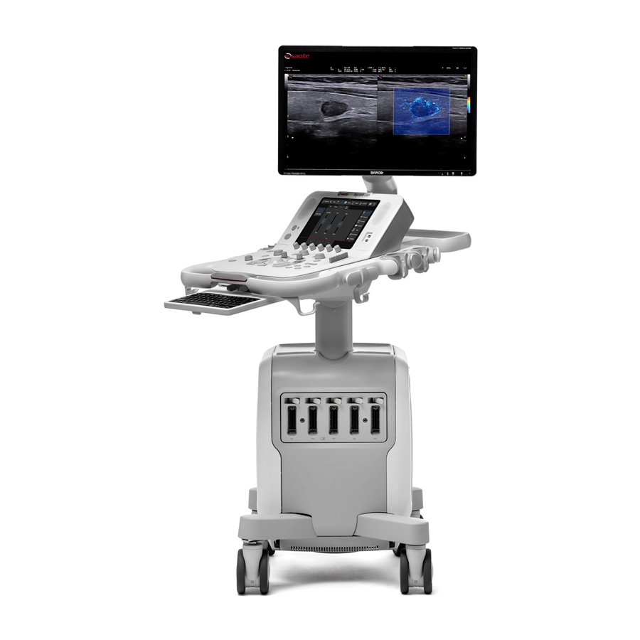
S Y S T E M O V E R V I E W System Components The system consists of a control panel assembly with LCD monitor and a console with the system electronics and connectors, housed in an ergonomic cart designed to be both highly mobile and adjustable for a range of users and operating conditions. -
Page 43: Monitor (1)
S Y S T E M O V E R V I E W Table 3-3: System components description Number System Component Monitor On/Off button Loudspeakers (on both sides) Control Panel Assembly Orientation lever Cable hangers Printer slot Connections panels Wheel brake pedal (on each pedal) Probe connectors... -
Page 44: On/Off Button (2)
S Y S T E M O V E R V I E W The monitor is suitable for reading medical images, in particular each production unit is calibrated according to the Greyscale Standard Display Function (GSDF) defined in Part 14 of the DICOM medical standard. In addition, the entire apparatus, of which the monitor is an integral part, complies with the mandatory standards of biomedical equipment (safety according to IEC 60601-1 Ed. -
Page 45: Control Panel Assembly (4)
S Y S T E M O V E R V I E W message. The following start up will require running the whole initialization phase. Control Panel Assembly (4) The Control Panel Assembly includes the main controls: physical buttons, knobs, and trackball, TGC, touchscreen and a pull-out QWERTY keyboard placed in the drawer below the panel. -
Page 46: Control Panel Assembly Orientation
S Y S T E M O V E R V I E W Table 3-5: Control Panel Assembly description Number Control Panel Assemble USB Port Loudspeakers Touch screen Knob controls TCG slide controls Trackball Two USB ports (17) are located on the right side of the control panel next to the touchscreen. -
Page 47: Pull-Out Qwerty Keyboard (12)
S Y S T E M O V E R V I E W Pull-out Qwerty Keyboard (12) Beneath the Control Panel there is a pull-out alphanumeric keyboard. The keyboard is mounted on a sliding drawer: just pull it to extract the keyboard. The keyboard is used to enter patient data, comments and text annotation on images. -
Page 48: Connections Panels (8)
S Y S T E M O V E R V I E W Connections panels (8) On the left side of the console you can find additional connections: ECG and Physio cable connector, auxiliary USB 3.0 ports that can be used to connect a USB printer, a USB footswitch or a USB digital archive medium, ... -
Page 49: Batteries
S Y S T E M O V E R V I E W Batteries can be equipped with an internal battery pack. MyLab The battery pack is installed by Esaote personnel. This person will be NOTE responsible for its installation and for ensuring that the system is working properly. -
Page 50: First Use
Esaote recommends to replace the battery pack every three years. The battery pack has to be replaced by Esaote personnel. This person will NOTE be responsible for ensuring that the system is working properly. -
Page 51: Error Messages
Save anyway the log file (refer to the “Archive” section of the Advanced Operation manual for further information) and contact the Esaote Service department. Errors in Battery Management The battery icon is shown crossed out whenever an error in the battery management occurs. -
Page 52: Power Supply Error Messages
Switch on again and check whether the MyLab message is still present. If the problem persists, contact Esaote personnel. Error #4 This error indicates that at least one of the batteries has reached the maximum temperature allowed for its working conditions. - Page 53 Please, contact the Service department. If this situation occurs, press and then shut down the system. Contact the Esaote Service department. Error #8 This error indicates that a fault of the impulse voltages occurs. The system displays the following message: Error #8: wrong impulse voltage.
- Page 54 S Y S T E M O V E R V I E W MyLab - G E T T I N G S T A R T E D 3 - 18...
-
Page 55: Preparing The System
Chapter 4. Preparing the System The system will be installed by Esaote personnel. Esaote personnel will be responsible for opening the packaging and ensuring that the system is correctly programmed and operational. The information and procedure provided in this chapter will guide to prepare the system for use. -
Page 56: Connecting Peripherals
MyLab usually already mounted and connected. The first mounting and connecting will usually be performed by an Esaote technician. Esaote suggests to contact its Service representative to install any auxiliary NOTE device. Before installing the peripheral devices, make sure that the system is switched off and unplug the power cable from the mains outlet. -
Page 57: Medical Environments
P R E P A R I N G T H E S Y S T E M Furthermore, all configurations shall comply with the requirements for medical electrical systems (see IEC 60601-1-1 or clause 16 of the 3rd Edition of IEC 60601-1, respectively). - Page 58 B or area C connected by cable (USB, HDMI,...) - Auxiliary device must be powered through a safety insulation transformer complying to IEC 60601. Auxiliary Devices must be approved by Esaote. Auxiliary Devices must also NOTE comply with EN 60601-1-2 safety standard and subsequent amendments or the electromagnetic compatibility.
- Page 59 The system must be powered so to satisfy the electrical safety requirements, WARNING as specified in the “Safety and Standards” manual. Esaote recommends running a current leakage (patient and environment) test when installing in order to check whether the applicable limits of standard EN60601-1 are not being surpassed.
-
Page 60: B/W Thermal Medical Usb Printer Housing
P R E P A R I N G T H E S Y S T E M B/W Thermal Medical USB Printer housing Those kinds of printers can be hosted in the lateral storage area. Procedure 1. Open the rear door. 2. -
Page 61: Auxiliary Monitor
P R E P A R I N G T H E S Y S T E M 8. Switch the printer on. Always power any USB device (such as USB printers or external USB WARNING archiving devices) through the trolley. Now the system can be connected to the mains and the entire configuration can be powered through the main switch. -
Page 62: External Cd/Dvd And Hdd Drives
Mechanical damage may MyLab occur if the drive falls down. The External Slim DVD Writer kit supplied by Esaote includes a Velcro tape to easily and securely fix it to console. Stick the tape both on the MyLab... - Page 63 P R E P A R I N G T H E S Y S T E M 10. Lock the monitor arm by rotating the lever on the monitor arm on lock position. 11. Release the wheel brakes and set the steering locks for comfortable moving.
-
Page 64: Mylab Quick Displacement
P R E P A R I N G T H E S Y S T E M Fig. 4-4: Transporting Configuration Protect the screen orientable arm so that no lateral movements are possible (for example with film). Use the brakes to lock the system. -
Page 65: Using The System
Chapter 5. Using the System This chapter provides a brief description of the system controls. Refer to the “Advanced Operations” manual for further detailed information. Connecting the system to the mains The power plug and the electrical main switch are located on the rear-bottom of the system. -
Page 66: System Controls
U S I N G T H E S Y S T E M 6. Connect the network and other cables from the system to the appropriate wall plugs. 7. Plug the cable to a reliable grounding power outlet to assure adequate grounding. - Page 67 U S I N G T H E S Y S T E M Table 5-1: Exam Control Buttons Button Description Toggles between factory and customized touchscreen that can be ETO UCH created by the user. Refer to the chapter “Customizing the system” further in this manual.
-
Page 68: Tgc Sliding
U S I N G T H E S Y S T E M Button Description Activates Generic Measurements showing the list of available +. . . + measurements on the right of the image. Changes the function linked to the trackball. Refer to the ACTI O N “Trackball”... -
Page 69: Trackball
U S I N G T H E S Y S T E M Trackball The trackball operates in two different modes. Standard Mode In its standard mode, the trackball makes it possible to quickly position the cursors on the screen. Each mode automatically activates the trackball on its cursor. -
Page 70: Touchscreen Section
U S I N G T H E S Y S T E M Touchscreen Section This section includes the and the buttons, a touchscreen and M EN U O N /O FF two USB ports. Menu Button displays the system menu for all configurations/settings (both clinical M EN U and system settings). - Page 71 U S I N G T H E S Y S T E M Table 5-3: Touchscreen key status Active Key with Disabled Key Active Key Selected Key Sub-menu Gray text on dark White text on light As Active Key with Blue text on dark gray background gray background...
- Page 72 U S I N G T H E S Y S T E M Multipurpose Panel This layout is used for advanced exam functions, for example bodymarks or Layout annotations. The touchscreen is organized in six main areas. Fig. 5-1: CFM touchscreen 1.
-
Page 73: Alphanumeric Keyboard Section
U S I N G T H E S Y S T E M bottom right button to switch between real-time and review. Swipe up to close. The touchscreen cannot be used for diagnosis. WARNING Alphanumeric Keyboard Section The alphanumeric keyboard is based on the QWERTY standard. The alphanumeric keys are used to enter text data in the enabled windows. -
Page 74: Heading Area
U S I N G T H E S Y S T E M 5. Thumbnails Area Controls on the Screen Layout are indicated in the operator manuals with , while strings and fields are indicated B O L D B L A C K C A P I T A L L E T T E R S with NORMAL BLACK CAPITAL LETTERS Symbol on Screen... -
Page 75: Wi-Fi
U S I N G T H E S Y S T E M Wi-Fi When Wi-Fi is enabled, its icon is shown beside the archival media icons. The icon is shown crossed out whenever Wi-Fi is not connected. For more details on Wi-Fi connectivity, consult the relevant section on the “Advanced Operations”... -
Page 76: Image Area
U S I N G T H E S Y S T E M Image Area The visualization of the image depends on various factors such as the active mode, the selected application and the probe. The following figure shows the elements in the image area that are independent of these factors. -
Page 77: Machine Parameters
U S I N G T H E S Y S T E M Machine Parameters Table 5-5: Imaging Parameters Displayed Parameter Description format Imaging or TEI (Tissue Enhancement Imaging) mode: General, Resolution or Penetration (L: Low, H: High) Imaging gain (Min,%, Max) Auto Adjust nn mm Depth... -
Page 78: Joystick Area
U S I N G T H E S Y S T E M Table 5-7: Doppler Parameters Displayed Parameter Description format nnn MHz Doppler frequency or TV (Tissue Velocity) frequency when enabled Doppler gain (Min,%, Max) nnn kHz Pulse Repetition Frequency Dynamic range / Rejection nnn Hz Wall filter... -
Page 79: Customizing The System
Chapter 6. Customizing the System can be customized to increase efficiency and streamline your work- MyLab flow. You can do the following: Create preset designed specifically for the exams you perform. Change system settings to reflect your needs. ... - Page 80 C U S T O M I Z I N G T H E S Y S T E M The menu is organized in three areas: Clinical Configuration, the upper area shows all options relating to Clinical Settings or Presets, ...
- Page 81 C U S T O M I Z I N G T H E S Y S T E M System Settings System Settings define the ’s parameters related to a specific system MyLab profile: Profile Manager, DICOM configuration, ...
-
Page 82: Generic Configuration Procedure
C U S T O M I Z I N G T H E S Y S T E M Generic Configuration Procedure Once accessed the configuration screen for the parameter you want to set, a common set of commands is available and a common setting procedure can be used. -
Page 83: Clinical Configurations
C U S T O M I Z I N G T H E S Y S T E M Clinical Configurations This chapter explains how to set many options. For configurations not MyLab described here refer to relevant chapters in the “Advanced Operations” manual. Real Time Preset A Preset is a group of settings that optimizes the system for a specific type of exam. -
Page 84: Creating A New Preset From Real-Time
C U S T O M I Z I N G T H E S Y S T E M Creating a new preset from Real-Time Procedure To create a new preset or modify an existing one: Adjust the real time image as desired in all modes (2D, CFM and Doppler). - Page 85 C U S T O M I Z I N G T H E S Y S T E M on the right the menu to record the macro and to edit the customized buttons, on the bottom the fields where customized touchscreens are named and described.
-
Page 86: System Settings
C U S T O M I Z I N G T H E S Y S T E M button adds a new tab that will be automatically displayed. Place N E W T A B the cursor on the tab and press to change its name, using the EN TER alphanumeric keyboard to edit it. -
Page 87: Corrupted System Profile
(no component has to be without any setting). Should this not solve the problem, contact Esaote personnel. Center ID Center ID allows to set the center name displayed in the Heading Area of the screen and the center information shown in the report. -
Page 88: General Setup
C U S T O M I Z I N G T H E S Y S T E M General Setup The menu is organized in internal folders, selectable using the tabs displayed on the top of the menu. Fig. -
Page 89: Measure Units Folder
C U S T O M I Z I N G T H E S Y S T E M Set Time Using the keyboard set the time. Time Format The time format is available on a 24 or 12 hour basis. In the 12 hour option, the time is shown as AM and PM. -
Page 90: Control Panel Folder
C U S T O M I Z I N G T H E S Y S T E M CONTROL PANEL Folder The table below lists and explains the available fields and the corresponding actions. Table 6-3: Control Panel Folder Fields Action TRACKBALL SPEED... -
Page 91: Field Shutdown Type
C U S T O M I Z I N G T H E S Y S T E M Fields Action DIRECT PROBE When checked, it allows to show on the SELECTION touchscreen work flow area icons of connected probes for quick change. -
Page 92: Field Available Qwerties
If a virus is found, it is advisable to switch off the , disconnect it from MyLab the data network and call the Esaote service, which will check for the presence of a virus and restore the system. Field AVAILABLE QWERTIES... - Page 93 C U S T O M I Z I N G T H E S Y S T E M Table 6-5: Application Preset Folder Fields Action ABSOLUTE ANGLE The angle correction factor of linear probes can be correlated either to the line cursor or to the line perpendicular to the transducer surface (absolute angle).
-
Page 94: Footswitch Folder
C U S T O M I Z I N G T H E S Y S T E M FOOTSWITCH Folder This option is used to set which function is associated to each pedal (left, middle and right) of the footswitch. Select from the curtain menu the function then press S A V E PROBE BUTTONS Folder... -
Page 95: License Activation
C U S T O M I Z I N G T H E S Y S T E M Press then to enter the License Manager Menu. It is L I C E N S E S M EN U organized in internal folders, selectable using the tabs displayed on the top of the menu. -
Page 96: Import/Export Menu
C U S T O M I Z I N G T H E S Y S T E M Import/Export Menu The menu is organized with internal folders, selectable using the tabs displayed on the top of the menu. Fig. -
Page 97: Import Folder
C U S T O M I Z I N G T H E S Y S T E M customized SAVING OPTIONS customized center configuration ( CENTER ID customized export settings; MULTIMEDIA customized configurations; NETWORK ... -
Page 98: System Info
ENCRYPTION MODE Encryption Mode Encryption allows to preserve health data storage confidentiality. Encryption can be performed by Esaote Service personnel only. Encryption can be applied to the internal hard disk and to one or more external USB memory devices. At the end of encryption a recovery key will be given to you. The recovery key is stored on USB pen drive, or on file, or by printing it. -
Page 99: Performing An Exam
Chapter 7. Performing an Exam This chapter describes the procedures commonly used in performing patient exams with . These procedures include entering patient and application MyLab data, acquiring images, making measurements and calculations; annotating and reviewing images. Read the “Safety and Standards” manual carefully: all the safety characteristics, cautions and warnings listed there apply to all exams. - Page 100 P E R F O R M I N G A N E X A M Fig. 7-1: Patient ID screen Fig. 7-2: Probe, Application, Preset touchscreen Starting exam The steps to be followed to start an exam are: procedure 1.
-
Page 101: Entering Patient And Application Data
P E R F O R M I N G A N E X A M Entering Patient and Application data There are two ways to enter patient data: Filling the Patient ID screen, Retrieving existing data from archive. Filling the Patient ID screen The Patient ID screen is used to enter patient data and application data, when applicable. -
Page 102: Selecting Probe
P E R F O R M I N G A N E X A M At any time during the exam, Patient Data can be viewed and modified by PATIENT ID pressing PATIENT ID Do not use to start a new exam of a new patient as it will update WARNING existing patient’s data with new entries. -
Page 103: Selecting Application
P E R F O R M I N G A N E X A M PROBE At any time during the exam, a different probe can be selected tapping or the new probe key on the touchscreen work flow area (available when is enabled). -
Page 104: Smart Preset
P E R F O R M I N G A N E X A M Smart Preset After exam starts, at the right side of the touchscreen, presets for the active probe and application are shown. When the preset is changed during the exam tapping one of them on the touchscreen, all acquisition parameters are reset while the geometrical characteristics (such as depth, size) are maintained. -
Page 105: Freeze And Scrolling Memories
P E R F O R M I N G A N E X A M Freeze and Scrolling Memories to stop and start real-time image acquisition and update. FREEZE pressure the system displays the scroll bar of the memories, FREEZE assigning the trackball to manual cineloop review (frame-by-frame). -
Page 106: Monitor Adjustments
P E R F O R M I N G A N E X A M Before archival, Patient Data can be made anonymous by checking the box. ANONYMIZE The native format of the exam can not be made anonymous. NOTE The exam can be simultaneously exported to the local archive and to external media (in native, DICOM and multimedia formats). -
Page 107: System Maintenance
Chapter 8. System Maintenance To ensure that operates over time at its maximum efficiency, Esaote MyLab recommends to perform maintenance procedures regularly. Maintenance procedures should be performed both by the user itself and by Esaote authorized service personnel. The maintenance operations and schedule are provided in the table below. - Page 108 Periodic maintenance operations that require the access to the system can NOTE be performed only by trained personnel: contact your local Esaote representative for further information on required periodic inspections. Only trained persons are allowed to perform the safety inspection mentioned above.
-
Page 109: Cleaning Operations
S Y S T E M M A I N T E N A N C E Cleaning Operations Periodic cleaning of the system and any connected devices is important. In the event of poor maintenance, dust and dirt can compromise the reliability and performance of and connected devices. -
Page 110: Cleaning Control Panel And System
S Y S T E M M A I N T E N A N C E A visual inspection of the parts subjected to the cleaning process in order to evaluate possible damages or deteriorations. Cleaning control panel and system To clean the control panel and system, switch the off, unplug it and use MyLab... -
Page 111: Cleaning Probe And Gel Holders
To clean the probes, refer to the manual “Probes and Consumables”. Sonogel and Scan MV gels, listed in Probes and Consumables manual as NOTE compatible with Esaote probes, have not been tested on plastic MyLab covers. Cleaning the Touchscreen... -
Page 112: Cleaning The Lcd Case
S Y S T E M M A I N T E N A N C E Cleaning the LCD case Use a soft, dry cloth to wipe the surface of the case. If necessary, apply a small amount of ammonia-free and not abrasive detergent onto a clean, soft cloth and then wipe the surface. -
Page 113: Technical Specifications
Licenses enable specific functions of the system, they are linked to the system serial number and are, therefore, unique. They should be carefully stored. The system is delivered by Esaote, with the licenses already installed. Additional features can be added buying the related license. - Page 114 T E C H N I C A L S P E C I F I C A T I O N S System Features Depending on the model, can be configured with one or more of the MyLab following features. Table 9-2: System Features Feature Description...
- Page 115 T E C H N I C A L S P E C I F I C A T I O N S Feature Description HyperDoppler Tool for the investigation of the intra-cardiac flows. Left Ventricular Opacification uses low mechanical index ultrasound to interact with 2nd generation contrast agents to enhance left ventricle (LV) visualization in difficult-to-scan patients.
-
Page 116: Technical Characteristics
XView+ pixel level, eliminating speckle and noise artefacts. a. Refer to www.esaote.com for further details on supported DICOM classes. b. Refer to the corresponding Sales Area manager for further information. Features, probes and applications availability is dependent on your system NOTE configuration. -
Page 117: Probe Connectors
Annotations, bodymarks 1. Auxiliary monitors connected to this input have not to be used for diagnostic purposes. 2. Refer to www.esaote.com for further details. MyLab - G E T T I N G S T A R T E D... -
Page 118: Keyboard
T E C H N I C A L S P E C I F I C A T I O N S Keyboard Height adjustable control panel Control panel: • Potentiometers for TGC • Encoders for general gains •... -
Page 119: Available Power On Peripherals
T E C H N I C A L S P E C I F I C A T I O N S Available power on peripherals Depending on the configuration, your can be equipped with one of the MyLab following Power Supply models: V1 model or V2 model. -
Page 120: Power Consumption
T E C H N I C A L S P E C I F I C A T I O N S Table 9-4: Maximum power available on peripheral outlets MyLab MyLab equipped with equipped with V1 model V2 model power supply power supply 110V... -
Page 121: Batteries
T E C H N I C A L S P E C I F I C A T I O N S Batteries Batteries for: • stand-by suspension • standard working condition Battery operating time: • up to 60 minutes with system on •... -
Page 122: Opti-Light
T E C H N I C A L S P E C I F I C A T I O N S Opti-light The monitor top edge hosts the Opti-light function that provides a subtle room lighting for optimal scanning conditions. The position of the lighting source eliminates any kind of reflection on the monitor resulting in improved image contrast resolution. -
Page 123: European And International Standards
T E C H N I C A L S P E C I F I C A T I O N S European and international standards Table 9-8: Standards Reference and title of the standard (and reference document) EN 60601-1:2006 Medical electrical equipment - Part 1: General requirements for basic safety and essential performance EN 60601-1:2006/AC:2010... - Page 124 T E C H N I C A L S P E C I F I C A T I O N S Reference and title of the standard (and reference document) EN 62366:2008 Medical devices - Application of usability engineering to Medical Devices IEC 62366:2015 EN ISO 10993-1:2009 Biological evaluation of medical devices - Part 1: Evaluation and testing within a risk...
Need help?
Do you have a question about the MyLabX8 and is the answer not in the manual?
Questions and answers