Table of Contents
Advertisement
Advertisement
Table of Contents

Related Manuals for Esaote MyLab


Summary of Contents for Esaote MyLab
- Page 1 Rev. O May 2015 MyLab GETTING STARTED OPERATOR MANUAL Doc # 81B13EN14...
- Page 2 G E T T I N G S T A R T E D M y L a b...
- Page 3 This chapter describes the MyLab user interface. • Chapter 6: Performing exam This chapter explains how an exam on the MyLab system is performed. • Chapter 7: Measurements and Calculations This chapter explains how measurements on an ultrasound image are performed.
- Page 4 G E T T I N G S T A R T E D M y L a b In this manual a WARNING pertains to possible injury to a patient and/or the W A R N I N G operator..
-
Page 5: Table Of Contents
Electromagnetic Compatibility_________________________________________________________________________1-1 Electromagnetic Emissions ___________________________________________________________________________1-2 Electromagnetic Immunity ___________________________________________________________________________1-2 Probe Surface Temperature ___________________________________________________________________________1-4 CLINICAL APPLICATIONS ____________________________________________________________2-1 Intended use________________________________________________________________________________________2-1 MyLab Applications ________________________________________________________________________________2-1 Clinical Applications _________________________________________________________________________________2-2 Cardiac Applications ________________________________________________________________________________2-3 Small Organs and Small Parts Application _______________________________________________________________2-3 Musculo-Skeletal Applications ________________________________________________________________________2-3 Abdominal and related Applications ____________________________________________________________________2-3... - Page 6 Control Tabs _______________________________________________________________________________________4-2 Connectivity and Battery Icons ________________________________________________________________________4-2 Archival Systems___________________________________________________________________________________4-2 Battery___________________________________________________________________________________________4-2 Wireless connectivity _______________________________________________________________________________4-3 Peripheral Units____________________________________________________________________________________4-3 User Interface Keys __________________________________________________________________________________4-3 Image Area_________________________________________________________________________________________4-4 Machine Parameters ________________________________________________________________________________4-5 GENERAL USER INTERFACE __________________________________________________________5-1 The User Interface___________________________________________________________________________________5-1 User section _______________________________________________________________________________________5-2 Freeze Mode Section ________________________________________________________________________________5-6 Settings Section ____________________________________________________________________________________5-8 Patient &...
- Page 7 SYSTEM MAINTENANCE_____________________________________________________________10-1 Cleaning of System and Peripheral Units _______________________________________________________________10-1 Veterinary Applications _____________________________________________________________________________10-1 11 - TECHNICAL SPECIFICATIONS ________________________________________________________11-1 Product Information and Optional Licenses _____________________________________________________________11-1 MyLab Technical Characteristics _____________________________________________________________________11-2 Display _________________________________________________________________________________________11-2 Probe connectors __________________________________________________________________________________11-2 Connectors_______________________________________________________________________________________11-2 Connectivity _____________________________________________________________________________________11-2 Image Files ______________________________________________________________________________________11-3 Basic Stand________________________________________________________________________________________11-3...
- Page 8 viii...
-
Page 9: Additional Information On Safety
M y L a b Chapter 1 - Additional Information on Safety This chapter provides additional information on safety specifically for MyLab products. Please read the "Safety and Standards" manual carefully for a complete overview of all safety aspects of products. -
Page 10: Electromagnetic Emissions
IEC 61000-4-4 1 kV for input/output If the user of MyLab requires continued lines operation during power mains interruption, it is recommended that the MyLab is powered 1 kV Pulse through an uninterruptible power supply or... - Page 11 80 MHz to 2.5 Recommended Distances between Radiofrequency (RF) Communication Systems and MyLab. As stated in the Safety and Standards manual, it is recommended not to use radiofrequency (RF) transmission systems near the ultrasound system. RF systems can cause interference, which can affect the ultrasound image.
-
Page 12: Probe Surface Temperature
Consequently, a direct measurement may be necessary of the environment in which is used. If the intensity of the MyLab electromagnetic fields exceeds to one that is specified in the previous tables, and the ultrasound system performs incorrectly, additional measurements may be necessary, i.e. -
Page 13: Clinical Applications
Intended use can be used for the following applications: MyLab Do not use for ophthalmic or transorbital applications. MyLabOne MyLab Applications Application Notes General Imaging Includes ABDOMEN (ABD), OVARY and SMALL ORGANS (testicles…)including transrectal exams Reproduction... -
Page 14: Clinical Applications
G E T T I N G S T A R T E D M y L a b Clinical Applications The tables below list probes and their intended clinical use. Please consult the MyLab corresponding chapter for specifications and licenses. LA Probes SL3323 Linear ... -
Page 15: Cardiac Applications
ABD: Abdominal; REP: Reproduction; CAR: Cardiac; SO: Small Parts and small organs; THY: Thyroid MS: Musculo-skeletal (including equine tendon); AS Animal Science; Do not use for ophthalmic or transorbital applications. MyLab W A R N I N G Cardiac Applications The probe applies ultrasound energy through the thoracic cavity to obtain an image of the heart sufficient for evaluating any cardiac abnormalities. - Page 16 – G E T T I N G S T A R T E D M y L a b operations, allows to identify surgical lesions, blood vessels and eventual anatomical abnormalities and technical imperfections. Do not use intraoperative probes in direct contact with the heart, the central W A R N I N G circulatory system and the central nervous system.
-
Page 17: System Components And Installation
Chapter 3 - System Components and Installation will be installed by ESAOTE personnel. This person is responsible for MyLab opening the packaging and ensuring that the system is correctly installed and is fully operational. This chapter provides an overview of the system's components and the most important operations that can be necessary. -
Page 18: Basic Stand Operation
G E T T I N G S T A R T E D M y L a b Basic Stand Operation Basic Stand can be used in MyLab combination with a Basic Stand. The Basic stand for has been MyLab designed for environments where a more robust solution is needed. -
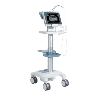
Page 19: Mobile Configuration
S T A R T E D M y L a b Mobile Configuration A height adjustable trolley is available to use in a mobile configuration. MyLab Height-adjustable The trolley is equipped with the attachment to trolley mount the scanner. -
Page 20: Battery
MyLab W A R N I N G system functions in an abnormal manner, produces unusual sounds or smell or overheats. In any of these cases please contact your Esaote representative. Do NOT open or alter batteries. W A R N I N G If the battery is incorrectly installed it may explode. - Page 21 M y L a b The charge icon is located next to the battery icon. If it is visible, MyLab connected to the mains power and the battery pack is recharged. B a tte r y s ta t u s l e d a n d O N / O F F b u tto n A battery status led is located inside the ON/OFF button on the left side of the system.
-
Page 22: Installation
Installation MyLab L o c a t i o n o f c o n tr o l s a n d p o r t s All the controls and ports are located on the exterior of the console and can be clearly identified. - Page 23 Starts/Shuts down the scanner Power connector To connect the adapter cable Desk Stand connector To connect to the Desk Stand MyLab Microphone Recording for Protocol Editor Kensington lock Anti-theft system Handle for ZIF Connector Locks the connected probe onto the system...
-
Page 24: Basic Stand
Do not switch off the machine before the initialization has finished. C A U T I O N MyLab H o w -to s e tu p i n A r m -H e l d C o n fi g u r a ti o n Make sure that is placed on a stable and horizontal work surface. - Page 25 To connect to a network DVI-I connector Connector with digital and analog signals for XVGA screens Lock button To lock the MyLab on the Desk Stand USB connector USB 2.0 Memory Stick, Printer Microphone connector To connect an external microphone...
-
Page 26: Trolley
Desk Stand. Trolley Installation of the trolley The trolley is supplied disassembled by ESAOTE. The appropriate assembly instructions are included. ESAOTE personnel will open the package and will ensure that the trolley is correctly assembled. Probe cable Connector holder... - Page 27 Adapter in trolley The same DC adapter used for in normal operation is also used to power MyLab if the system is mounted on the trolley. Open the cover on the base of the MyLab Installation trolley, place the DC adapter in the middle and mount the bracket that is used to adapter hold the adapter into position.
-
Page 28: Acclimation Time
If MyLab W A R N I N G the MyLab is not firmly secured it can fall down during movement of the trolley Near the bottom of the trolley there is a pedal to adjust the working height. -
Page 29: Installing The Peripheral Units
The system must be powered to satisfy the electrical safety requirements, as W A R N I N G specified in the "Safety and Standards" manual. ESAOTE recommends running a current leakage (patient and environment) test when installing in order to check whether the applicable limits of standard EN60601-1 are not being surpassed. -
Page 30: Installation On A Trolley
S T A R T E D M y L a b In this latter case, peripheral units must be powered ensuring compliance with the medical security standards: please contact Esaote Service department to correctly install them. Note When peripherals units are not powered by the trolley, it is good practice not to touch simultaneously the patient and the peripheral unit. -
Page 31: Additional Connectors
The wheels of are equipped with brakes; be sure the brakes MyLab trolley are disabled before moving the ultrasound apparatus. Avoid any unnecessary mechanical shocks to the system while moving it. Be sure that the probes are locked with the connector-securing lock in the... -
Page 32: Transportation
– G E T T I N G S T A R T E D M y L a b With height adjustable trolley, do not use the handles to lift the system. Transportation When transporting the system on a vehicle, remember to: ... -
Page 33: Screen Lay-Out
M y L a b Chapter 4 - Screen Lay-Out This chapter provides a brief description of the information on the screen. MyLab Information about the Screen The screen is subdivided into four main areas: Connectivity and Control Tabs Battery Icons... -
Page 34: Control Tabs
When used in arm-held configuration, the user can turn over the to the left, MyLab right (portrait mode) or even upside down. The screen will adapt automatically the user interface to the current orientation. -
Page 35: Wireless Connectivity
Both interfaces can be enabled or disabled. MyLab is equipped with Wireless Connectivity generating RF signals. W A R N I N G Attention needs to be paid to possible interferences with other devices and equipments in the vicinity. -
Page 36: Image Area
– G E T T I N G S T A R T E D M y L a b In the user interface keys area the application and preset buttons are present too. They permit to select the application suitable for the procedure and the preferred preset with the preferred settings. -
Page 37: Machine Parameters
– G E T T I N G S T A R T E D M y L a b Box (zoom or color/power) movement and resize: by dragging by the center of the sliders on right side and below the ultrasound image it is possible to position the box;... - Page 38 – G E T T I N G S T A R T E D M y L a b...
-
Page 39: General User Interface
G E T T I N G S T A R T E D M y L a b – Chapter 5 - General User Interface This chapter provides a brief description of the system controls The User Interface The user interface is touch screen based and consists of keys, sliders and tabs. It is also possible to enable a keyboard on screen when text has to be edited in text fields. -
Page 40: User Section
G E T T I N G S T A R T E D M y L a b – Please note that the look of the buttons on the screen is related to their status and the availability of the buttons related to function. If the button is active, pressing the key enables the displayed function. - Page 41 G E T T I N G S T A R T E D M y L a b – The gain slider will appear when the area beneath the Gain Controllider is presets is touched. used for adjusting the amplification of This slider is used for adjusting the amplification of the the echo signal.
- Page 42 G E T T I N G S T A R T E D M y L a b – mode can be used to adjust the gain settings of the image, in case the ADJUST image is to bright or the dark. The auto-adjust function will bring back the setting of the Gain and the TGC to a level to generate a good image.
- Page 43 G E T T I N G S T A R T E D M y L a b – Note The programmable button must have an active function to be able to select it.. button will open a submenu containing several functions. These MORE functions will be described hereinafter.
-
Page 44: Freeze Mode Section
G E T T I N G S T A R T E D M y L a b – key saves still images. IMAGE key enables the biopsy environment used for biopsy procedures BIOPSY key changes right/ left or left/ right orientation. REVERSE During the exam the key freezes the trace acquisition and the reference... - Page 45 G E T T I N G S T A R T E D M y L a b – key allows adding bodymarks to the current image. MARK Further details on how to use them are described in the "Advanced Operations" manual.
-
Page 46: Settings Section
G E T T I N G S T A R T E D M y L a b – key saves still images. The key is used to save sequences of frames IMAGE CLIP (for systems having the clip license). The length of the clips depends on the length of the cine loop and on actions of the user. -
Page 47: Performing An Exam
MyLab is equipped with Wireless Connectivity generating RF signals. W A R N I N G Attention needs to be paid to possible interferences with other devices and equipments in the vicinity. - Page 48 – G E T T I N G S T A R T E D M y L a b Note To guarantee data integrity and confidentiality, the system configures a list of users allowed to work on the system. In this case to access the system the user needs to log in and type a password.
-
Page 49: End Exam
– G E T T I N G S T A R T E D M y L a b At any time during the exam, the operator can view the patient's data by pressing Query in database . The operator can modify the patient’s data during the PATIENT &... - Page 50 – G E T T I N G S T A R T E D M y L a b key allows a search operation of stored exams through the database. If Exam not closed QUERY a patient is already in the archive, it is possible to retrieve the patient’s data from an archived exam without having to enter them again.
- Page 51 – G E T T I N G S T A R T E D M y L a b During an exam the user can export the current exam to external media by the button. EXPORT When the previous data is not stored and the is pressed, a warning CLOSE EXAM message appears.
-
Page 52: Select An Exam Through Dicom
– G E T T I N G S T A R T E D M y L a b The user can: Close the exam by entering the name of the patient. Press to go back to the exam (if possible). CANCEL Further details are When no Patient Database is enabled the user only has the possibility to export the... - Page 53 – G E T T I N G S T A R T E D M y L a b With the button, patient data can be accessed over DICOM and this SELECT EXAM data can directly be used as input for a new exam. The following buttons and their uses are described: o Refresh Data: when selecting this box the opened exam will always be checked to be certain it is the last updated version.
-
Page 54: Performing The Exam
– G E T T I N G S T A R T E D M y L a b Performing the Exam By pressing the different mode keys, the specific mode is activated in real time. Before beginning the exam, make sure that the active probe displayed on W A R N I N G the screen matches the requirements for the procedure to be performed. -
Page 55: Freeze Mode And Scrolling Memories
Clips are compressed for digital storage. Compressed files involve a minimal loss of information (see Technical Specifications Chapter 11). The Compression algorithm used by ensures the preservation of the image features for the reporting MyLab functions. Note Digital data storage is typically slower than the ultrasound frame rate;... -
Page 56: Exam Review
– G E T T I N G S T A R T E D M y L a b Exam Review During the exam, it is possible to review the saved image by selecting the thumbnail on the right column of the screen. If there are more than seven saved images and clips, the arrows beneath the thumbnails column allows the operator to quickly scroll the thumbnails: the next seven thumbnails are displayed when the key is pressed. -
Page 57: System Shut Down
– G E T T I N G S T A R T E D M y L a b System Shut Down This is a PC based system; data loss may occur due to power loss or after C A U T I O N emergency shutdown (by pressing the shutdown button for 3 seconds). - Page 58 – G E T T I N G S T A R T E D M y L a b 6-12...
-
Page 59: Measurements And Calculations
G E T T I N G S T A R T E D M y L a b – Chapter 7 - Measurements and Calculations This chapter describes how to access the generic measurements and the specific application measurements. General Information Measurements can be made on frozen images. -
Page 60: Specific Calculation Packages
G E T T I N G S T A R T E D M y L a b – The measurements can be arranged in groups (identified by the symbol +), with corresponding main measurements including sub-parameters. To display the measurements included in a group, press the symbol + and the measurements will be visible. - Page 61 G E T T I N G S T A R T E D M y L a b – To measure a specific parameter from a measurement group, press the + symbol to expand, and then press the required item. At the bottom of the screen, the system displays operating instructions to guide the user during the measurement.
- Page 62 G E T T I N G S T A R T E D M y L a b –...
-
Page 63: Exams Archive
PATIENT & ARCHIVE Data Archival has an internal hard disk in which the exams can be archived (local archive). MyLab The data can be also saved on external supports and on DICOM format (for Refer to the “System systems having a DICOM license), and exported in BMP, PNG, JPEG, format or Configuration”... - Page 64 – G E T T I N G S T A R T E D M y L a b Close Exam An exam can be archived and stored on the system after pressing the CLOSE EXAM key. When the previous data is not stored and the is pressed, a warning CLOSE EXAM message appears.
-
Page 65: Review Of Archived Exams
– G E T T I N G S T A R T E D M y L a b Review of Archived Exams The operator can reload and review exams saved in the database. The images can be reloaded and a specific exam can be reviewed for each patient. Selecting tab displays the following page. -
Page 66: End Of Review
The maximum current supplied by the USB ports of is 500mA. MyLab W A R N I N G Peripherals requiring more power and exceeding this limit can be connected ONLY IF powered by their own external power supply. -
Page 67: System Menu
– G E T T I N G S T A R T E D M y L a b Chapter 9 - System Menu Configuration Menu key provides access to the system menu. The key is available by MENU MENU accessing the tab. -
Page 68: Main Menu Sections
Peripherals All the peripheral devices that can be connected to MyLab can be configured in this menu environment. Types of peripherals are from DICOM to the digital printer and the wireless. -
Page 69: Cleaning Of System And Peripheral Units
W A R N I N G the ultrasound machines used in veterinary applications should be thoroughly cleaned at least once every 6 months. Please contact your Esaote distributor/ dealer for further help in this matter. Turn off the system before any cleaning operation. Liquid, also spray, may W A R N I N G cause electrical shock. - Page 70 – G E T T I N G S T A R T E D M y L a b Do not use detergents or other liquids directly on the screen. Immediately C A U T I O N dry any drops of water that may fall on the screen as they could stain the screen.
-
Page 71: Technical Specifications
11 - Technical Specifications This chapter describes the technical specifications of the MyLab Note For detailed information on how to operate the scanner please refer to the Advanced Operations manual. Product Information and Optional Licenses Veterinary Use including General Imaging Vet, Cardio, TEI, X-View, TP-View, MyLibrary , Animal Science and Reproduction small and large animals. -
Page 72: Mylab Technical Characteristics
• Animal Science IMF license • Application licenses o Reproduction Porcine Ovine Llama license o Equine MSK/Tendon License MyLab Technical Characteristics This section provides technical information of the system; please refer to the previous paragraph for possible configurations. Display •... -
Page 73: Image Files
– G E T T I N G S T A R T E D M y L a b Image Files • Formats • Standard output file formats (BMP, PNG, JPEG, AVI) • Native and DICOM formats • Clips characteristics •... -
Page 74: Desk Stand Pro
– G E T T I N G S T A R T E D M y L a b Desk Stand Pro Connectors • 3 USB 2. 0 • LAN RJ45 • Footswitch • DVI-I • Audio line-out • Microphone •... -
Page 75: Mains Adapter
Trolley Configuration Pro Connectors • Docking connector Dimensions • Height: approx.: Min. 1060 – Max. 1300 mm MyLab • Height with installed: approx. Min. 1130 – Max. 1370 mm • Base dimensions: approx. 570 (L) x 470 mm (W) •... -
Page 76: Multicon
G E T T I N G S T A R T E D M y L a b Dimensions • Height: approx.: 1210 mm MyLab • Height with installed: approx. 1280 mm • Base dimensions: approx. 570 (L) x 470 mm (W) •... - Page 77 – G E T T I N G S T A R T E D M y L a b SV3L11 11-7...
- Page 78 – G E T T I N G S T A R T E D M y L a b 11-8...
Need help?
Do you have a question about the MyLab and is the answer not in the manual?
Questions and answers