Table of Contents
Advertisement
Quick Links
Advertisement
Table of Contents

Related Manuals for Esaote MyLabOmegaVET


Summary of Contents for Esaote MyLabOmegaVET
- Page 1 Rev. 08 November 2020 MyLabOmegaVET GETTING STARTED 350038000...
- Page 2 MyLab - G E T T I N G S T A R T E D...
-
Page 3: Manufacturer's Address
MyLabOmegaVET For US Customers: US Federal Law restricts this device to sale, distribution and use by or on the order of a physician. All information included in this manual is relative to the following Esaote ultrasound equipments: MyLabOmegaVET In this manual, all the above mentioned devices are referred to as MyLab Unless specifically noted, sections of this manual pertain to all the devices. -
Page 4: Guarantee
Guarantee The information in this document is the exclusive property of Esaote S.p.A. and is reserved. Reproduction or distribution in any form is strictly prohibited. All rights reserved. All screenshots, pictures and graphics in this manual are used for descriptive purposes only and may be different from what you see on the screen or device. -
Page 5: Ec Declaration Of Conformity
EC Declaration of Conformity MyLab - G E T T I N G S T A R T E D... -
Page 6: Red Declaration Of Conformity
RED Declaration of Conformity MyLab - G E T T I N G S T A R T E D... - Page 7 MyLab - G E T T I N G S T A R T E D...
- Page 8 MyLab - G E T T I N G S T A R T E D viii...
-
Page 9: Table Of Contents
I N D E X Table of Contents Manufacturer’s Address ................i-iii Important Information ................i-iii Guarantee..................... i-iv Trade Marks....................i-iv EC Declaration of Conformity..............i-v RED Declaration of Conformity ............. i-vi 1 Introduction.................. 1-1 Safety and Standards................1-1 Getting Started ................... 1-1 Probes and Consumables.............. - Page 10 I N D E X Recommended Distances between Radiofrequency (RF) Communication Systems and MyLab..........2-6 Wireless Requirements ................2-7 3 MyLab Overview................3-1 About MyLab....................3-1 Intended Use.....................3-1 Clinical Applications and Supporting Probes ........3-2 Contraindications ..................3-4 MyLab Overview..................3-5 Portable Configuration................3-5 Identifying the Connectors ...............3-6 Installing the Portable Configuration ..........3-8 Accessories for Outdoor Transport..........3-8 Probe Connections ..................3-9...
- Page 11 I N D E X MyLab Controls ..................5-2 Control Panel Section ................5-2 EKnob ....................5-4 Trackball ....................5-4 Touchscreen Section................5-5 On/Off Button .................. 5-5 Menu Button..................5-6 Touchscreen..................5-6 TGC Sliding ..................5-9 Information about the Screen Layout ........... 5-10 Heading Area..................
- Page 12 EXPORT Folder ................6-19 IMPORT Folder ................6-20 System Info .....................6-21 Encryption Mode................6-21 Manuals Manager ...................6-22 Electronics manuals on Esaote website ........6-22 7 Performing an Exam..............7-1 Starting an Exam ..................7-1 Entering Patient and Application data..........7-3 Filling the Patient ID screen .............7-3 Retrieving data from archive.............7-3 Selecting Probe ..................7-4...
- Page 13 I N D E X 9 Technical Specifications............... 9-1 MyLab Characteristics................9-1 Licenses..................... 9-1 Technical Characteristics ................9-4 Display....................... 9-4 Probe connectors..................9-4 Connectivity ..................... 9-4 Image Files....................9-5 Software ....................9-5 Biometry....................9-5 Keyboard ....................9-5 Dimensions....................9-5 Weight ....................... 9-6 IP Grade....................
- Page 14 I N D E X MyLab - G E T T I N G S T A R T E D...
-
Page 15: Introduction
MyLabOmegaVET family, or when the contents are common to the other MyLab ultrasound devices belonging to the Esaote platform. MyLab Safety and Standards The Safety and Standard manual contains information about the patient's and operator's safety. -
Page 16: Advanced Operations Manual
NOTE Specifications subject to change without notice. Information might refer to products or modalities not yet approved in all countries. Product images are for illustrative purposes only. For further details, please contact your Esaote sales representative. This manual refers to... -
Page 17: Intended Audience
Before reading these instructions for use, you need to be familiar with ultrasound techniques. Sonography training and clinical procedures are not included here. Veterinary Use Esaote offers dedicated software intended for veterinary use, providing specific probes and measurements. The application of our imaging diagnostic devices to other species/ WARNING practices as well as for conventional species is done under veterinary specialist's exclusive responsibility, knowledge and belief. - Page 18 I N T R O D U C T I O N Special attention should be dedicated to intra-cavitary probes (e.g. vaginal, rectal or oesophageal probes). They should be cleaned according to established protocols (AIUM guidelines for cleaning probes) and should not be used if there is noticeable self-heating of the probe when operating in air.
-
Page 19: Mylab Use
Use of the product for the purposes other than those intended and expressly stated by Esaote, as well as incorrect use or operation, may relieve Esaote or its agents from all or some responsibility for resultant noncompliance, damage, or injury. -
Page 20: Manufacturer's Responsibility
NOTE related to risks for patient, operator or device. Manufacturer’s Responsibility Esaote is responsible for the safety, reliability and functioning of this product only if: the user follows all the instructions contained in the device manuals for the use and the maintenance of this device;... -
Page 21: Maintainability Time
Esaote qualified personnel, using original Esaote spare parts. When approaching the seven (7) years limit from the purchase date, it is recommended to contact Esaote Service or to visit Esaote web site (www.esaote.com), to get updated information on the product’s end of life and/or to agree on the most suitable solution for its safe disposal. -
Page 22: Proprietary Rights
For any software updates and/or upgrades installed on the Equipment after installation, the terms herein shall apply in full. License Rights and Limitations With this license, Esaote S.p.A. grants the end user the right to use the on the supplied SOFTWARE... -
Page 23: Third Part Software
I N T R O D U C T I O N Third Part Software Esaote software uses parts of the 7-Zip program. The 7-Zip is licensed under the GNU LGPL license; the source code can be found in www.7-zip.org. - Page 24 I N T R O D U C T I O N PRODUCT TRACEABILITY FORM To: ESAOTE S.p.A. Quality Assurance Department Via Enrico Melen, 77 16152, Genova, Italy [or associate company] [or authorized distributor] Esaote system/device name:..................REF..........................Serial Number (SN):....................
-
Page 25: Vigilance System
Esaote central plants, or one of our subsidiaries, or one of our official distributors immediately through the following form, or through a communication reporting the same data contained in this form. - Page 26 I N T R O D U C T I O N POST-MARKET SURVEILLANCE FORM ACCIDENT REPORT FORM To: ESAOTE S.p.A. Quality Assurance Department Via Enrico Melen, 77 16152, Genova, Italy [or associate company] [or authorized distributor] [or competent authorities] ESAOTE system/device name:................
-
Page 27: Additional Information On Safety
Chapter 2. Additional Information on Safety This chapter provides additional information on safety specifically for MyLab products. Please read the “Safety and Standards” manual carefully for a complete overview of all safety aspects of products. MyLab Environmental Safety Special waste The device contains lithium-ion batteries. -
Page 28: Electromagnetic Compatibility
A D D I T I O N A L I N F O R M A T I O N O N S A F E T Y Electromagnetic Compatibility This device was designed for use in the electromagnetic environments declared in the tables below, in compliance with standard IEC 60601-1- 2:2014 (4 edition). -
Page 29: Essential Performance
A D D I T I O N A L I N F O R M A T I O N O N S A F E T Y Use of accessories, transducers and cables other than those specified or WARNING provided by the manufacturer of this equipment could result in increased electromagnetic emissions or decreased electromagnetic immunity of this... -
Page 30: Electromagnetic Immunity For All Medical Equipment
A D D I T I O N A L I N F O R M A T I O N O N S A F E T Y Electromagnetic Immunity for All Medical Equipment MyLab is intended for use in the electromagnetic environment specified below. The customer or MyLab the user of should assure that it is used in such an environment. -
Page 31: Electromagnetic Immunity For Medical Equipment Not Life Supporting
A D D I T I O N A L I N F O R M A T I O N O N S A F E T Y MyLab is intended for use in the electromagnetic environment specified below. The customer or MyLab the user of should assure that it is used in such an environment. -
Page 32: Recommended Distances Between Radiofrequency (Rf) Communication Systems And Mylab
A D D I T I O N A L I N F O R M A T I O N O N S A F E T Y Recommended Distances between Radiofrequency (RF) Communication Systems and MyLab As stated in the “Safety and Standards” manual, it is recommended not to use radiofrequency (RF) transmission systems near the ultrasound scanner. -
Page 33: Wireless Requirements
A D D I T I O N A L I N F O R M A T I O N O N S A F E T Y Wireless Requirements is equipped with built-in wireless capability. MyLab When wireless is active, the operator should make sure to stay at a minimum distance of 20 cm from the rear of the equipment. - Page 34 A D D I T I O N A L I N F O R M A T I O N O N S A F E T Y MyLab - G E T T I N G S T A R T E D 2 - 8...
-
Page 35: Mylab Overview
Chapter 3. MyLab Overview is a professional, innovative and versatile real-time high- MyLabOmegaVET resolution ultrasound scanner. The wide range of probes makes it suitable for many clinical applications. About MyLab Intended Use is intended to perform images of the internal structure of the MyLabOmegaVET animal’s body that, when interpreted by a medical expert trained in the use of... -
Page 36: Clinical Applications And Supporting Probes
M Y L A B O V E R V I E W Clinical Applications and Supporting Probes A variety of ultrasound probes can be connected to MyLabOmegaVET AC2541 including biopsy capabilities IH 6-18 IL 4-13 including biopsy capabilities IOT342... - Page 37 M Y L A B O V E R V I E W Table 3-1: Available probes and applications Probes Application Abdominal bovine AC2541, IL 4-13, IOT342, L 3-11, LA435, mC 3-11, P 1-5, SB2C41, SC3123, SI2C41, SL3116 Abdominal canine AC2541, IH 6-18, IL 4-13, IOT342, L 3-11, L 4-15, LA435, mC 3- P 1-5, P 2-9, P2 5-13, SB2C41, SC3123, SI2C41, SL1543, SL2325, SL3116...
-
Page 38: Contraindications
NOTE MyLab exam type. Not all applications are approved in all Countries. Please refer to your Esaote local representative for further information. Contraindications is not intended for: MyLabOmegaVET ophthalmic use or any use causing the acoustic beam to pass through the eye. -
Page 39: Mylab Overview
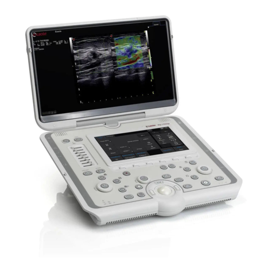
S Y S T E M O V E R V I E W MyLab Overview has a built-in LCD screen: in this way, the device can be used as MyLab portable configuration. can be supplied with a trolley in its mobile MyLab configuration. -
Page 40: Identifying The Connectors
S Y S T E M O V E R V I E W is equipped with an external AC/DC adapter and, as an option, with MyLab internal batteries. Identifying the Connectors Table 3-2: Connectors on right side Connector Symbol Description EA1÷EA2 Two probe connectors... - Page 41 The mains socket is located on the rear side of . Connect the AC/DC MyLab adapter to the mains socket. is equipped with an AC/DC adapter, Esaote P/N 151004301 (see label MyLab on the AC/DC adapter). Use only the AC/DC adapter provided by Esaote with the...
-
Page 42: Installing The Portable Configuration
S Y S T E M O V E R V I E W Installing the Portable Configuration Refer further in this chapter Place the on the work surface using the handle as sloping support. MyLab for information on probe Position the equipment so that the power outlet is easily accessible. -
Page 43: Probe Connections
S Y S T E M O V E R V I E W Fig. 3-2: MyLab Fold-away Trolley Before using carefully clean it and the fold-away trolley after they MyLab CAUTION have been transported outdoor. Probe Connections Both imaging and Doppler probes can be connected to the two (2) connectors, indicated by the EA1 and EA2 symbols. -
Page 44: Mobile Configuration
S Y S T E M O V E R V I E W Make sure that the securing device is placed in the lower position (open position) and carefully attach the probe connector by placing the cable feedthrough frontwards. To secure the probe, move the securing device up. Do not touch the probe connector pins or the probes receptacle. -
Page 45: Basic Mobile Configuration
S Y S T E M O V E R V I E W Basic mobile configuration In its basic configuration (picture above), the trolley is supplied with holders for probes, cables and gel. Insert the holders on the trolley lateral stirrups and place them in the desired position. -
Page 46: Accesorized Mobile Configuration
S Y S T E M O V E R V I E W Accesorized mobile configuration The trolley can be equipped with many accessories: Insulation transformer, Probe multi-connector, Auxiliary monitor. Insulation The insulation transformer is mounted under the base of the trolley. The transformer insulation transformer is always necessary when other optional accessories are mounted on the trolley. -
Page 47: Connections Of Mobile Configuration
S Y S T E M O V E R V I E W The auxiliary monitor must be powered through the power supply P/N 530000137 connected to the insulation transformer through the jumper P/N 8820074000, both P/Ns provided by Esaote. Connections of mobile configuration Fig. 3-5: Insulation transformer + probe multi-connector Fig. -
Page 48: Batteries
S Y S T E M O V E R V I E W Batteries can be equipped with an internal battery pack. MyLab The battery pack is installed by Esaote personnel. This person will be NOTE responsible for its installation and for ensuring that the device is working properly. -
Page 49: First Use
Esaote recommends to replace the battery pack every three years. The battery pack has to be replaced by Esaote personnel. This person will NOTE be responsible for ensuring that the device is working properly. -
Page 50: Error Messages
MyLab again to see whether the error message persists. Save anyway the log file (refer to the “Archive” section of the Advanced Operation manual for further information) and contact the Esaote Service department. Errors in Battery Management The battery icon is shown crossed out whenever an error in the battery management occurs. -
Page 51: Power Supply Error Messages
Switch on again and check whether the MyLab message is still present. If the problem persists, contact Esaote personnel. Error #4 This error indicates that at least one of the batteries has reached the maximum temperature allowed for its working conditions. - Page 52 S Y S T E M O V E R V I E W If this situation occurs, press and then shut down . Contact the MyLab Esaote Service department. Error #8 This error indicates that a fault of the impulse voltages occurs. displays MyLab the following message: Error #8: wrong impulse voltage.
-
Page 53: Preparing For Use
To use connectivity features, the device must be connected to a network. The LAN plug is placed at the bottom of the rear side; it supports Gigabit, 10Base-T, and 100Base-T Ethernet LAN. An Esaote field engineer or your network administrator must configure for network connectivity. -
Page 54: Connecting Peripherals
, are usually MyLab already mounted and connected. The first mounting and connecting will usually be performed by an Esaote technician. Esaote suggests to contact its Service representative to install any auxiliary NOTE device. Before installing the peripheral devices, make sure that... -
Page 55: Medical Environments
P R E P A R I N G T H E S Y S T E M complies with the requirements for medical electrical systems. Attention is drawn to the fact that local laws take priority over the above mentioned requirements. - Page 56 B or area C connected by cable (USB, HDMI,...) - Auxiliary device must be powered through a safety insulation transformer complying to IEC 60601. Auxiliary Devices must be approved by Esaote. Auxiliary Devices must also NOTE comply with EN 60601-1-2 safety standard and subsequent amendments or the electromagnetic compatibility.
- Page 57 The system must be powered so to satisfy the electrical safety requirements, WARNING as specified in the “Safety and Standards” manual. Esaote recommends running a current leakage (patient and environment) test when installing in order to check whether the applicable limits of standard EN60601-1 are not being surpassed.
-
Page 58: Peripheral Housing
P R E P A R I N G T H E S Y S T E M Peripheral housing When is set in a mobile configuration (refer to chapter 3 for further MyLab details), the trolley can house a peripheral on the dedicated tray. When selecting the peripheral, consider its dimension so that it can be NOTE safely installed on the dedicated tray. - Page 59 P R E P A R I N G T H E S Y S T E M Before connecting any peripheral, verify that the total power consumption CAUTION does not exceed 350VA that is the maximum power available on insulated sockets.
-
Page 60: Moving And Transporting The System
P R E P A R I N G T H E S Y S T E M Moving and Transporting the System Portable Configuration Disconnect all probes, peripherals and the AC/DC adapter. Close the LCD screen being sure that the safety push-buttons are closed. Always use the handle to move the system. -
Page 61: Mylab Quick Displacement
P R E P A R I N G T H E S Y S T E M To steadily lock the system, all the wheels must be locked. Do not park the system on a slope. Do not use the brakes to park the machine on a slope. Avoid any unnecessary mechanical shock to the system while moving it. - Page 62 P R E P A R I N G T H E S Y S T E M MyLab - G E T T I N G S T A R T E D 4 - 10...
-
Page 63: Using Mylab
Chapter 5. Using MyLab This chapter provides a brief description of the device controls. Refer to the “Advanced Operations Manual” for further detailed information. Connecting MyLab to the mains The power plug and the electrical main switch (when present) are located on the rear-bottom of the . -
Page 64: Mylab Controls
U S I N G M Y L A B When installing , check that the power cable is not tightly bent, that MyLab WARNING it can’t be squashed by a misplaced foot or by heavy objects. Place in a location allowing an easy unplug of from the mains MyLab MyLab... - Page 65 U S I N G M Y L A B Button Description key, available on both CFM and Doppler AUTO ADJUST LEFT AUTO ADJUST modes, automatically adjusts some controls of the active mode to AN D make the echo acquisition easier. DO PPLER GAI N The knob around this key amplifies CFM, CW and PW gains over...
-
Page 66: Eknob
U S I N G M Y L A B Button Description Stops the current analysis or scan and puts MyLab in Freeze mode. FREEZE To re-activate real time, press it again or directly press the button of the required mode. This button re-activates a B-Mode image in real time when any other mode is active. -
Page 67: Touchscreen Section
U S I N G M Y L A B Table 5-2: Trackball cursors Mode Trackball M-Mode, Doppler LINE cursor Color Flow Mapping (CFM) CFM ROI cursor The cursor function is indicated below the image. When several cursors are present on the screen, switches between the active cursors. -
Page 68: Menu Button
U S I N G M Y L A B Pressing the button turns on or off, activating or closing the MyLab O N /O FF examination session. Optional Batteries When is equipped with optional batteries, the same button places the MyLab device in stand-by, partially shutting it down: in this case the initialization phase at start up is significantly reduced. - Page 69 U S I N G M Y L A B Fig. 5-1: CFM touchscreen 1. Navigation area, it contains the navigation tabs allowing to select the desired features for the relevant controls. For example B-Mode, CFM. 2. Main area, it contains main controls, varying according to the active mode, application and settings.
- Page 70 U S I N G M Y L A B Table 5-4: Touchscreen key status Active Key with Disabled Key Active Key Selected Key Submenu Gray text on dark White text on light As Active Key with Blue text on dark gray background gray background three lines at...
-
Page 71: Tgc Sliding
U S I N G M Y L A B Fig. 5-2: Annotations touchscreen Refer to the “Advanced Operations” manual for further details. Alphanumeric The alphanumeric keyboard is based on the QWERTY standard. The Keyboard Layout alphanumeric keys are used to enter text data in the enabled windows. The Caps Lock key sets the keyboard to upper case characters. -
Page 72: Information About The Screen Layout
U S I N G M Y L A B Information about the Screen Layout The screen is split into four main areas. Fig. 5-3: Screen Layout 1. Heading Area 2. Footer Area 3. Image Area 4. Thumbnails Area Controls on the Screen Layout are indicated in the operator manuals with , while strings and fields are indicated B O L D B L A C K C A P I T A L L E T T E R S with... -
Page 73: Footer Area
U S I N G M Y L A B Footer Area This area is used to display the following information: trackball functionality, Wi-Fi icon (when enabled), archival media icons, advanced features icons, battery icons, peripherals icons. Trackball When the trackball can perform multiple functions, the next function is indicated below the image as yellow text. -
Page 74: Image Area
U S I N G M Y L A B Image Area The visualization of the image depends on various factors such as the active mode, the selected application and the probe. The following figure shows the elements in the image area that are independent of these factors. Fig. -
Page 75: Machine Parameters
U S I N G M Y L A B Machine Parameters Table 5-6: Imaging Parameters Displayed Parameter Description format Imaging or TEI (Tissue Enhancement Imaging) mode: General, Resolution or Penetration (L: Low, H: High) Imaging gain (Min,%, Max) Auto Adjust nn mm Depth C or +n/n... -
Page 76: Thumbnails Area
U S I N G M Y L A B Table 5-7: Color Flow Mapping (CFM) Parameters Displayed Parameter Description format VM (Tissue Velocity nnn MHz Color frequency or T Mapping) frequency when enabled Color gain (Min,%, Max) nnn kHz Pulse Repetition Frequency Wall filter Smooth (L: Low, M: Medium, H: High) /... -
Page 77: Customizing Mylab
Chapter 6. Customizing MyLab can be customized to increase efficiency and streamline your work- MyLab flow. You can do the following: Create preset designed specifically for the exams you perform. Change device settings to reflect your needs. Add options to enhance your imaging abilities. Create custom procedures for specific patients, transducers, and presets. - Page 78 C U S T O M I Z I N G M Y L A B The menu is organized in three areas: Clinical Configuration, the upper area shows all options relating to Clinical Settings or Presets, System Settings, the central area shows all options relating to System Settings, General Settings, the lower area shows all options relating to General Settings.
- Page 79 C U S T O M I Z I N G M Y L A B System Settings System Settings define the ’s parameters related to a specific device MyLab profile: Profile Manager, DICOM configuration, Saving Options for end exam saving configuration, Center ID for hospital configuration to set the name of the hospital, Multimedia,...
-
Page 80: Generic Configuration Procedure
C U S T O M I Z I N G M Y L A B Generic Configuration Procedure Once accessed the configuration screen for the parameter you want to set, a common set of commands is available and a common setting procedure can be used. -
Page 81: Clinical Configurations
C U S T O M I Z I N G M Y L A B Clinical Configurations This chapter explains how to set many options. For configurations not MyLab described here refer to relevant chapters in the “Advanced Operations” manual. Real Time Preset A Preset is a group of settings that optimizes for a specific type of... -
Page 82: Creating A New Preset From Real-Time
C U S T O M I Z I N G M Y L A B Creating a new preset from Real-Time Procedure To create a new preset or modify an existing one: Adjust the real time image as desired in all modes (2D, CFM and Doppler). - Page 83 C U S T O M I Z I N G M Y L A B on the right the menu to record the macro and to edit the customized buttons, on the bottom the fields where customized touchscreens are named and described.
-
Page 84: System Settings
C U S T O M I Z I N G M Y L A B button adds a new tab that will be automatically displayed. Place N E W T A B the cursor on the tab and press to change its name, using the EN TER alphanumeric keyboard to edit it. -
Page 85: Corrupted System Profile
(no component has to be without any setting). Should this not solve the problem, contact Esaote personnel. Center ID Center ID allows to set the center name displayed in the Heading Area of the screen and the center information shown in the report. -
Page 86: General Setup
C U S T O M I Z I N G M Y L A B General Setup The menu is organized in internal folders, selectable using the tabs displayed on the top of the menu. Fig. 6-3: General Configuration Menu saves the settings, which will be activated as soon as they are saved. -
Page 87: Measure Units Folder
C U S T O M I Z I N G M Y L A B Format Displayed date MMM/DD/YYYY Apr/01/2011 Set Time Using the keyboard set the time manually. Time Format The time format is available on a 24 or 12 hour basis. In the 12 hour option, the time is shown as AM and PM. -
Page 88: Control Panel Folder
C U S T O M I Z I N G M Y L A B CONTROL PANEL Folder The table below lists and explains the available fields and the corresponding actions. Table 6-3: Control Panel Folder Fields Action TRACKBALL SPEED Sets the speed of the trackball. -
Page 89: Field Shutdown Type
When the OFF button is pressed, MyLab performs an VIRUS SCAN ONCE antivirus scan and then a complete shut-down. At the next OFF pressure the previous choice is restored. Esaote does not install a real-time antivirus program, because it could affect NOTE the regular operations of MyLab The antivirus scan could take a long time. -
Page 90: Field Available Qwerties
If a virus is found, it is advisable to switch off the , disconnect it from MyLab the data network and call the Esaote service, which will check for the presence of a virus and restore MyLab Field AVAILABLE QWERTIES... - Page 91 C U S T O M I Z I N G M Y L A B Table 6-5: Application Preset Folder Fields Action ABSOLUTE ANGLE The angle correction factor of linear probes can be correlated either to the line cursor or to the line perpendicular to the transducer surface (absolute angle).
-
Page 92: Footswitch Folder
C U S T O M I Z I N G M Y L A B Fields Action When checked, pressing PW from B-Mode, MyLab 1-CLICK CHANGEOVER ENABLED FOR PW, switches to B-Mode frozen + Doppler live at once. CW, M-MODES When not checked, pressing PW from B-Mode, MyLab switches to B live + PW frozen. -
Page 93: Security Folder
The update from the web requires a web access and it can take long time to finish, so a message warns you before starting. is not enabled and can be used from Esaote Service personnel only. If S C A N you want to perform an antivirus scan, you have to perform a shut-down with virus scan. -
Page 94: License Activation
C U S T O M I Z I N G M Y L A B To activate a new license, the operator needs the appropriate form listing NOTE the licenses associated to the device. License codes are generated according to the Hardware ID, shown on the left upper corner of the MyLab license configuration menu. -
Page 95: Import/Export Menu
C U S T O M I Z I N G M Y L A B Import/Export Menu The menu is organized with internal folders, selectable using the tabs displayed on the top of the menu. Fig. 6-6: Import/Export Menu EXPORT Folder This option allows the user to save customized clinical and system settings on the USB medium. -
Page 96: Import Folder
C U S T O M I Z I N G M Y L A B customized SAVING OPTIONS customized center configuration ( CENTER ID customized export settings; MULTIMEDIA customized configurations; NETWORK customized OBSERVATIONS customized printer profiles ( PRINTERS customized report styles ( REPORTS customized settings;... -
Page 97: System Info
ENCRYPTION MODE Encryption Mode Encryption allows to preserve health data storage confidentiality. Encryption can be performed by Esaote Service personnel only. Encryption can be applied to the internal hard disk and to one or more external USB memory devices. At the end of encryption a recovery key will be given to you. The recovery key is stored on USB pen drive, or on file, or by printing it. -
Page 98: Manuals Manager
UPDATE MANUALS you have to update manuals on your own. If this particular case happens, the package for the update is provided by the Esaote service. This remote case is communicated by through a warning message at starting-up. - Page 99 C U S T O M I Z I N G M Y L A B 5. Select the language you desire; 6. Click on the manual to open it or click on to download it. You can download the entire set of manuals by clicking on NOTE DOWNLOAD ALL FILES (.ZIP).
- Page 100 C U S T O M I Z I N G M Y L A B MyLab - G E T T I N G S T A R T E D 6 - 24...
-
Page 101: Performing An Exam
Chapter 7. Performing an Exam This chapter describes the procedures commonly used in performing patient exams with . These procedures include entering patient and application MyLab data, acquiring images, making measurements and calculations; annotating and reviewing images. Read the “Safety and Standards” manual carefully: all the safety characteristics, cautions and warnings listed there apply to all exams. - Page 102 P E R F O R M I N G A N E X A M Fig. 7-1: Patient ID screen Fig. 7-2: Probe, Application, Preset touchscreen Starting exam The steps to be followed to start an exam are: procedure 1.
-
Page 103: Entering Patient And Application Data
P E R F O R M I N G A N E X A M Entering Patient and Application data There are two ways to enter patient data: Filling the Patient ID screen, Retrieving existing data from archive. Filling the Patient ID screen The Patient ID screen is used to enter patient data and application data, when applicable. -
Page 104: Selecting Probe
P E R F O R M I N G A N E X A M At any time during the exam, Patient Data can be viewed and modified by PATIENT ID pressing PATIENT ID Do not use to start a new exam of a new patient as it will update WARNING existing patient’s data with new entries. -
Page 105: Selecting Application
P E R F O R M I N G A N E X A M PROBE At any time during the exam, a different probe can be selected tapping or the new probe key on the touchscreen work flow area (available when is enabled). -
Page 106: Performing The Exam
P E R F O R M I N G A N E X A M Performing the Exam offers a set of imaging modes to cover a variety of imaging needs. By MyLab pressing the different mode buttons the specific mode is activated in real time. -
Page 107: Reviewing Images
P E R F O R M I N G A N E X A M Reviewing Images EXAM REVIEW During the exam, taping enables reviewing of the saved images and sequences, and the trackball automatically changes to pointer mode, allowing you to scroll through the thumbnails and select the item to be reviewed. - Page 108 P E R F O R M I N G A N E X A M At power-up, prompts the operator to archive the last exam NOTE MyLab performed if the device was switched off without first closing the exam in progress.
-
Page 109: Maintenance
Chapter 8. Maintenance To ensure that operates over time at its maximum efficiency, Esaote MyLab recommends to perform maintenance procedures regularly. Maintenance procedures should be performed both by the user itself and by Esaote authorized service personnel. The maintenance operations and schedule are provided in the table below. -
Page 110: Veterinary Applications
Refer to “Probes and Consumables” manual for periodic inspections for probes and cleaning instructions. Veterinary Applications Due to the specificity of the veterinary working place, Esaote recommends WARNING that the ultrasound devices used in veterinary applications should be thoroughly cleaned at least once every 6 months. Please contact your Esaote distributor or dealer for further help in this matter. -
Page 111: Cleaning Operations
M A I N T E N A N C E Cleaning Operations Periodic cleaning of and any connected devices is important. MyLab In the event of poor maintenance, dust and dirt can compromise the reliability and performance of and connected devices. MyLab The following table indicates the cleaning agents that have tested the compatibility with the... -
Page 112: Cleaning Control Panel And Device
M A I N T E N A N C E Check the instructions supplied by the manufacturer of the cleaning agents for possible stricter limitation. Do not use hot cleaning agents for cleaning the equipment. Apply the cleaning agents only for the time necessary to remove the dirt CAUTION without exceeding over. -
Page 113: Cleaning Probe And Gel Holders
M A I N T E N A N C E When cleaning the trackball housing, make sure not to spray any liquid into CAUTION the trackball housing. Clean the ball rotating it in its socket. Do not remove the ball from the socket. Do not remove the ball from the socket. -
Page 114: Cleaning The Lcd Screen
M A I N T E N A N C E Cleaning the LCD Screen To clean the LCD use a soft dry cloth, lightly rubbing the display surface to remove dust and other particulate matter. If necessary, apply a small amount of ammonia- free glass cleaner onto a clean, soft cloth and then wipe the surface. -
Page 115: Technical Specifications
MyLab number and are, therefore, unique. They should be carefully stored. The device is delivered by Esaote, with the licenses already installed. Additional features can be added buying the related license. 1. Specifications subject to change without notice. Information might refer to products or modalities not yet approved in all countries. - Page 116 T E C H N I C A L S P E C I F I C A T I O N S Applications can be equipped with the following application licenses. MyLab Table 9-1: Application licenses Licence Application Features General Imaging Abdominal Canine, Abdominal Presets, Calculations...
- Page 117 T E C H N I C A L S P E C I F I C A T I O N S Feature Description ElaXto ElaXto allows you to perform elastosonographic analysis of the tissues ElaXto Measures It enables measurements in elastosonography Possibility to visualize the MyLab images on different devices eStreaming on the same network...
-
Page 118: Technical Characteristics
XView+ pixel level, eliminating speckle and noise artifacts. a. Refer to www.esaote.com for further details on supported DICOM classes. b. Refer to the corresponding Sales Area manager for further information. Features, probes and applications availability is dependent on your device NOTE configuration. -
Page 119: Image Files
Closed (approximately): 380 (w) x 98 (h) x 380 (d) mm In working position: 380 (w) x 360 (h) x 400 (d) mm 1. Refer to www.esaote.com for further details. MyLab - G E T T I N G S T A R T E D... -
Page 120: Weight
T E C H N I C A L S P E C I F I C A T I O N S Weight 6.4 kg approximately, without batteries 7.5 kg approximately, with batteries IP Grade IP (X)0, this means models are not watertight. -
Page 121: Probe Storage Requirements
T E C H N I C A L S P E C I F I C A T I O N S Pressure: 700 1060 hPa Probe Storage Requirements Probe storage requirements are indicated in the probe case. Standards Table 9-3: Standards Standard Title... - Page 122 T E C H N I C A L S P E C I F I C A T I O N S Standard Title EN ISO 14971:2012 Medical equipment - Application of risk management to medical devices. ISO 15223-1 Medical devices - Symbols to be used with medical device labels, labeling and information to be supplied - Part 1: General Requirements...
Need help?
Do you have a question about the MyLabOmegaVET and is the answer not in the manual?
Questions and answers