Table of Contents
Advertisement
Advertisement
Table of Contents

Related Manuals for Sauder Sewing/Craft Cart


Summary of Contents for Sauder Sewing/Craft Cart
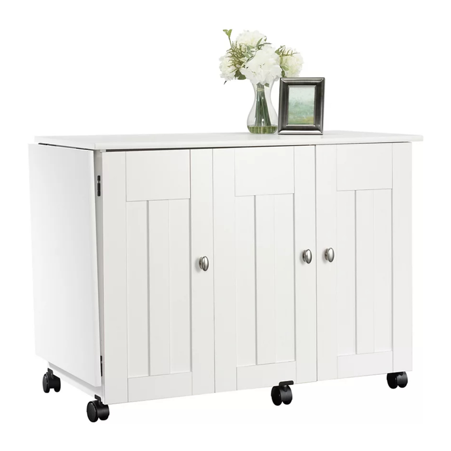
- Page 1 We'll have you in stitches. Sewing/Craft Cart...
- Page 2 Table of Contents Assembly Tools Required Part Identifi cation No. 2 Phillips Screwdriver Tip Shown Actual Size Hardware Identifi cation Assembly Steps 5-18 Hammer Not actual size Français 19-21 Español 22-24 Safety 25-26 Warranty Page 2...
-
Page 3: Part Identification
Part Identifi cation å While not all parts are labeled, some of the parts will have a label or an inked letter on the edge to help distinguish similar parts from each other. Use this part identifi cation to help identify similar parts. RIGHT END (1) BOTTOM (1) RIGHT DOOR (1) -
Page 4: Hardware Identification
Hardware Identifi cation å Screws are shown actual size. You may receive extra hardware with your unit. LOCKING CASTER - 2 CASTER - 4 TRAY - 2 TRAY DIVIDER - 8 17E CASTER BRACKET - 6 HIDDEN CAM - 14 CAM DOWEL - 14 TIGHT HINGE- 2 LOOSE HINGE- 2... - Page 5 Step 1 Assemble your unit on a carpeted fl oor or on the empty carton to å avoid scratching your unit or the fl oor. Push fourteen HIDDEN CAMS (1F) into the ENDS (A and B), å UPRIGHT (C2), BOTTOM (F), MODESTY PANEL (G2), and SHELF (H2).
- Page 6 Step 2 Fasten the RIGHT END (A) to the TOP (D2). Tighten two å Caution HIDDEN CAMS. Do not stand the unit upright without the BACK fastened. The unit may collapse. i t h f a c S u r D E N H I D Finished edge...
- Page 7 Step 3 Fasten the BOTTOM (F) to the RIGHT END (A). Tighten å two HIDDEN CAMS. Maximum Arrow 210 degrees Minimum 190 degrees Finished edge Page 7...
- Page 8 Step 4 Fasten the UPRIGHT (C2) to the TOP (D2) and BOTTOM (F). å Tighten four HIDDEN CAMS. Maximum Arrow 210 degrees Fasten two MAGNETIC CATCHES (5I) to the UPRIGHT (C2). å Use two BLACK 1-1/8" PAN HEAD SCREWS (9S). Minimum Fasten the MODESTY PANEL (G2) to the UPRIGHT (C2).
- Page 9 Step 5 Fasten the SHELF (H2) to the UPRIGHT (C2). Use two å BLACK 1-15/16" FLAT HEAD SCREWS (113S). Maximum Arrow 210 degrees Fasten the LEFT END (B) to the TOP (D2), MODESTY å PANEL (G2), and SHELF (H2). Tighten six HIDDEN CAMS. Minimum 190 degrees 113S...
- Page 10 Step 6 Carefully turn your unit over onto its front edges. Lay the å Caution BACK (I) over your unit. Do not stand the unit upright without the Make equal margins along three edges of the BACK (I). Push å BACK fastened.
- Page 11 Step 7 Fasten the FLIP-UP TOP (E) to the TOP (D2). å Use two HINGES (16H) and eight BLACK 9/16" Remember: LARGE HEAD SCREWS (1S). Righty tighty. Lefty loosey. BLACK 9/16" LARGE HEAD SCREW (8 used in this step) Page 11...
- Page 12 Step 8 Place a CASTER BRACKET (17E) over the holes in the å unfi nished edges of the ENDS (A and B) and UPRIGHT (C2). Push the stems of the LOCKING CASTERS (2CL) through å the holes in the CASTER BRACKETS and completely into the lower holes in the ENDS (A and B).
- Page 13 Step 9 Fasten the TIGHT HINGES (2H) to the RIGHT DOOR (K). å Use four BLACK 9/16" LARGE HEAD SCREWS (1S). Fasten a STRIKE PLATE (6I) to the RIGHT DOOR (K). å Use a BLACK 1/2" FLAT HEAD SCREW (11S). The TIGHT HINGE has no gap.
- Page 14 Step 10 Carefully stand your unit upright. å Pro Tip: Lift with your Fasten the RIGHT DOOR (K) to the RIGHT END (A). Use å legs. And, you know, four BLACK 9/16" LARGE HEAD SCREWS (1S). your arms. Fasten a KNOB (19K) to the RIGHT DOOR (K). Use a å...
- Page 15 Step 11 Fasten the LOOSE HINGES (3H) to the LEFT DOOR (L). Use four BLACK 9/16" LARGE HEAD SCREWS (1S). å Fasten the remaining HINGES (16H) to the CENTER DOOR (J) and LEFT DOOR (L). Use twelve BLACK 9/16" LARGE å...
- Page 16 Step 12 Fasten the LEFT DOOR (L) to the LEFT END (B). Use four å BLACK 9/16" LARGE HEAD SCREWS (1S). Fasten two KNOBS (19K) to the CENTER DOOR (J) and LEFT å DOOR (L). Use two GOLD 1" MACHINE SCREWS (50S). BLACK 9/16"...
- Page 17 Step 13 NOTE: The FLIP-UP TOP (E) can be supported by å the DOORS (J and L). There are two holes in the bottom surface of the FLIP-UP TOP (E) for the bolt in the SLIDE CATCH (6J) to lock into. Fasten the TRAYS (2D) to the CENTER DOOR (J) å...
- Page 18 Step 14 Push the RUBBER SLEEVES (2R) over the METAL PINS (1R). å Insert the METAL PINS into the hole locations of your choice in If you're doing this to the RIGHT END (A) and UPRIGHT (C2). Set the ADJUSTABLE help a friend, don't SHELVES (M) onto the METAL PINS.
-
Page 19: Liste De Pièces
élément et conserver le livret EXTRÉMITÉ DROITE ..........1 EXCENTRIQUE ESCAMOTABLE ....14 pour future référence. EXTRÉMITÉ GAUCHE ..........1 CHEVILLE D'EXCENTRIQUE ......14 Pour contacter Sauder en ce qui concerne cet MONTANT................1 CHARNIÈRE SERRÉE..........2 élément, faire référence DESSUS ................1 CHARNIÈRE DESSERRÉE ........2 au numéro de lot et... - Page 20 ÉTAPE 1 ÉTAPE 6 Ne pas serrer les EXCENTRIQUES ESCAMOTABLES dans Attention : Ne pas relever l'élément dans sa position verticale cette étape. avant d'avoir fi xé l’ARRIÈRE. L'élément risque de s'eff ondrer. Assembler l'élément sur un sol à moquette ou sur le carton vide Avec précaution, retourner l'élément sur ses chants avant.
-
Page 21: Excentrique Escamotable
ÉTAPE 10 ÉTAPE 13 Relever, avec précaution, l'élément dans sa position verticale. REMARQUE : Le DESSUS RELEVABLE (E) peut être supporté par les PORTES (J et L). Il y a deux trous dans la surface inférieure Fixer la PORTE DROITE (K) à l'EXTRÉMITÉ DROITE (A). Utiliser du DESSUS RELEVABLE (E) pour le boulon dans l’ARRÊTOIR DE quatre VIS TÊTE LARGE 14 mm NOIRES (1S). -
Page 22: Lista De Partes
Si EXTREMO IZQUIERDO ..........1 BISAGRA SUELTA ............2 necesita ponerse en PARAL ...................1 16H BISAGRA ................5 contacto con Sauder en PANEL SUPERIOR ............1 AGARRADOR MAGNÉTICO .......2 cuanto a esta unidad, refi érase al número PANEL SUPERIOR ABATIBLE PLACA DE CONTACTO .........2 de lote y al número de... - Page 23 PASO 1 PASO 6 No apriete los EXCÉNTRICOS ESCONDIDOS en este paso. Precaución: No coloque la unidad en posición vertical hasta que se fi je el DORSO. La unidad podría caerse. Ensamble la unidad sobre un piso alfombrado o sobre el cartón vacío para evitar rayar la unidad o el piso.
-
Page 24: Excéntrico Escondido
PASO 10 PASO 13 Cuidadosamente ponga la unidad en posición vertical. NOTA: El PANEL SUPERIOR ABATIBLE HACIA ARRIBA (E) puede ser apoyada por las PUERTAS (J y L). Hay dos agujeros Fije la PUERTA DERECHA (K) al EXTREMO DERECHO (A). Utilice en la superfi... - Page 25 WARNING Please use your furniture correctly and safely. Improper use can cause safety hazards, or damage to your furniture or household items. Carefully read the following chart. Look out for: What can happen: How to avoid the problem: • Overloaded drawers and shelves. •...
- Page 26 ADVERTENCIA Por favor use el mobiliario correcta y seguramente. El mal uso puede causar riesgos de seguridad o daño a las unidades o artículos domésticos. Cuidadosamente lea la tabla a continuación. Esté alerto de: Puede ocurrir: Evitar el problema: • El sobrecargo de cajones y estantes. •...
-
Page 27: Year Limited Warranty
2. There is no warranty coverage for defects or conditions that result from the failure the laws of certain states, there may be no implied warranties from Sauder and all to follow product assembly instructions, information or warnings, misuse or abuse, implied warranties, INCLUDING ANY IMPLIED WARRANTY OF MERCHANTABILITY intentional damage, fi... - Page 28 Certifi cate of Conformity 1. This certifi cate applies to the Sauder Woodworking Product identifi ed by this Instruction Book. 2. This certifi cate applies to compliance of this product with the CPSC Ban on Lead-Containing Paint (16 CFR 1303).
Need help?
Do you have a question about the Sewing/Craft Cart and is the answer not in the manual?
Questions and answers