Table of Contents
Advertisement
Quick Links
Installation, Operation & Maintenance
177-997 Rev D
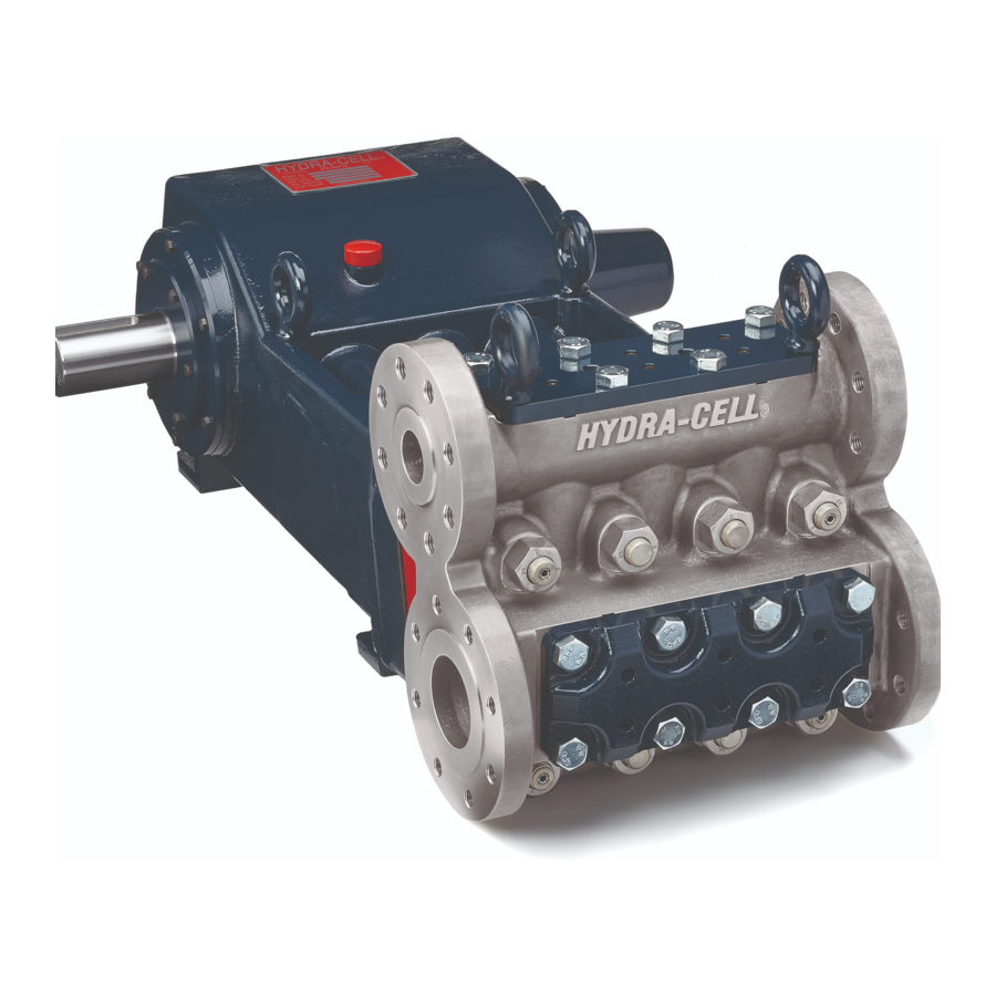
T100 Series Low Pressure
Models: T100E, T100F, and T100H
W0550A
1204 Chestnut Avenue, Minneapolis, MN
T e l : ( 6 1 2 ) 3 3 2 - 5 6 8 1
F a x : ( 6 1 2 ) 3 3 2 - 6 9 3 7
Toll-free fax [US only]: (800) 332-6812
www.hydra-cell.com
email: sales@wannereng.com
55403
Advertisement
Table of Contents

Related Manuals for Hydra-Cell T100 Series


Summary of Contents for Hydra-Cell T100 Series
- Page 1 Installation, Operation & Maintenance 177-997 Rev D T100 Series Low Pressure Models: T100E, T100F, and T100H W0550A 1204 Chestnut Avenue, Minneapolis, MN 55403 T e l : ( 6 1 2 ) 3 3 2 - 5 6 8 1...
-
Page 2: Component Identification
T100 Series Low Pressure - Contents Component Identification Page Component Identification ........2 Specifications ............2 Power End Float Switch & Oil Fill Cap Sight Glass Dimensions ............4 with Dipstick Outlet Installation .............6 Oil Fill Cap Maintenance ............10 Service (Fluid End) ..........11 Service (Hydraulic Section) .........13... -
Page 3: Net Positive Suction Head
T100 Series Low - Specifications (Cont’d) Performance Net Positive Suction Head – NPSHr T100E 5.048 T100F 4.548 4.048 3.548 T100H 3.048 Revolutions per Minute Revolutions Per Minute 500-E 1000-E 1500-E 500-F 1000-F 1850-F 500-H 1000-H 2100-H Calculating Required Horsepower (kW)*... -
Page 4: Front View
T100 Series Low Pressure - Dimensions inches (mm) 4.83 Center of mass (123) 3.50 Minimum full key (89) 0.75 X 0.75 Keyway (19.05 X 19.05) W0554A 29.11 (739) Front View 2X .08 18.50 (470) 3.00 Top View (76.2) 177-997 Rev D... -
Page 5: Side View
T100 Series Low - Dimensions (Cont’d) inches (mm) ASME B16.5 43.00 3-1/2” CLASS 300 RF (1092) (8x 3/4-10 UNC-2B) Inlet Both Sides ASME B16.5 Center of mass 2” CLASS 900 RF (8x 7/8-9 UNC-2B) Outlet Both Sides 1/2-14 NPT 19.44... -
Page 6: Important Precautions
T100 Series Low Pressure - Installation Location Important Precautions Locate the pump as close to the fluid supply source as Adequate Fluid Supply. To avoid cavitation and premature pump possible. failure, be sure that the pump will have an adequate fluid supply and Install it in a lighted clean space where it will be easy to that the inlet line will not be obstructed. - Page 7 T100 Series Low - Installation (Cont’d) Accessories Do not use a line strainer or filter in the suction line unless regular maintenance is assured. If used, choose a top loading Consult installation drawing below for typical system components. basket. It should have a free-flow area of at least three times Contact Wanner Engineering or the distributor in your area for the free-flow area of the inlet.
-
Page 8: Discharge Piping
T100 Series Low - Installation (Cont’d) Pressure Relief Minimizing Acceleration Head and Frictional Losses To minimize the acceleration head and frictional losses: Install a pressure relief valve in the discharge line. Bypass pressure must not exceed the pressure limit of the pump. -
Page 9: Initial Start-Up
T100 Series Low - Installation (Cont’d) Initial Start-Up 1. Pump must be at or above minimum temperature specified in diaphragm temperature limits table for 24 hours prior to starting. 2. Open the bypass line start-up and capacity-control valve so the pump may be started against negligible discharge pressure. -
Page 10: Maintenance
2000 hours or six months, whichever Internal retaining ring pliers comes first. 8 in. adjustable wrench Note: Hydra-Cell T100 Series Pumps come standard with Torque wrench or torque multiplier adjustable from 650 to 900 10W30 motor oil. ft-lbs (881 to 1220 N-m). -
Page 11: Fluid End Parts
T100 Series Low Pressure - Fluid End Service WARNING: Manifold (84) and assembled parts weigh over 500 pounds (227 kg) and require mechanical lift. Use care in handling to prevent personal injury or damage to equipment. Outlet Valve See Detail A... - Page 12 T100 Series Low - Fluid End Service (Cont'd) This section explains how to disassemble and inspect all easily- d. Inspect discharge retainer plates for warping or wear around serviceable parts of the pump. discharge ports. Look for corrosion, scale and wear. If wear is excessive, replace discharge retainer plate.
- Page 13 T100 Series Low - Hydraulic Section Service CAUTION - For servicing of pumps certified for use in • Small puncture. Usually caused by a sharp foreign object explosive atmospheres (ATEX/IECEx) please see separate in the fluid. supplementary manual. • Diaphragm pulled away from the center screw or from the cylinder sides.
- Page 14 T100 Low - Hydraulic Section Service (Cont’d) Hydraulic Section Disassembly (Cont’d) Diaphragm Plate Disassembly WARNING: Manifold (84) and assembled parts weigh over 200 pounds (91 kg) and are a two man lift. Use care in handling to prevent personal injury or damage to equipment.
- Page 15 T100 Low - Hydraulic Section Service (Cont’d) Airbleed Valve W0564A Underfill Valve Overfill Valve Valve Parts View 177-997 Rev D...
- Page 16 T100 Low - Hydraulic Section Service (Cont’d) Hydraulic Section Assembly Diaphragm Assembly a. See Diaphragm Parts View. Diaphragm Plate Assembly CAUTION: It is important to observe the following steps d. and e. to ensure proper assembly. WARNING: Diaphragm plate (52) and assembled parts weigh over 100 pounds (45 kg) and are a two b.
- Page 17 T100 Low - Hydraulic Section Service (Cont’d) Hydraulic Section Assembly (Cont’d) Eight hex nuts (26) W0563B Eight bolts (101) Torque sequence: Torque sequence: Snug eight hex nuts (26) in order indicated to torque value - Snug eight hex nuts (26) in order indicated, listed on page 21.
-
Page 18: Power End Disassembly
T100 Series Low Pressure - Power End Service Power End Disassembly Crankshaft Removal a. Remove six cap screws (15) from one side of pump attaching WARNING: Crankcase (2) and assembled parts weigh seal and bearing assembly (assembled items 6, 7, 9, 11, 15, over 400 pounds (181 kg) and are a two man lift. -
Page 19: Crankshaft Installation
T100 Series Low - Power End Service (Cont’d) Power End Assembly Crankshaft Installation a. Install one seal and bearing assembly to either side of WARNING: Crankcase (2) and assembled parts weigh crankcase (2) using six screws (15). Crankshaft (1) will be over 400 pounds (181 kg) and are a two man lift. - Page 20 T100 Series Low - Power End Service (Cont’d) Float Switch Back Cover Assembly a. Align and assemble frame (44), gasket (43), sight glass (42), and thick gasket (41). b. Install eight screws (45) alternately through assembled frame into back cover (12) until snug.
- Page 21 T100 Series Low Pressure - Oil Level Monitor Oil Level Monitor Float Switch Note: The oil level should always be visible between the high and low oil marks viewed on sight glass (42). If the Conditions and Wiring Diagram oil level reaches the high or low mark, the float switch will be activated.
- Page 22 T100 Series Low - Oil Level Monitor (Cont'd) Oil Level Monitor Float Switch Electrical Specifications - Class I Conditions and Wiring Diagram - Division 1 Class I Division 1 The following are the maximum electrical rating for Class I Division 1 float switches:...
- Page 23 T100 Series Low - Torque Specifications T100E,F,H Torque Specification Table Reference Number Torque Specification Loctite No. Part Number Description (N-m) 100 ft-lbs (136) 177-003-02 Bolts, Connecting Rod Assembly 200 ft-lbs (271) 177-059 Eyebolt, M20 12 ft-lbs (16) 177-048 Screw, Cap, hex-hd, M8, 25 mm...
-
Page 24: Fluid End
T100 Series Low Pressure - Fluid End Parts W0550A Fluid End Outlet Valve See Detail A Detail A Disc* * Carbide Valves include Disc as matched set. Inlet Valve See Detail A W0551A Note: for torque values refer to the Torque Specifications Table. - Page 25 T100 Series Low Pressure - Fluid End Parts Ref. Quantity/ Ref. Quantity/ No. Part Number Description Pump No. Part Number Description Pump 14 177-059 Eyebolt, M20 ........2 98 177-310 Plate, Retainer, discharge CV ....1 26 177-152 Nut, Hex, M27 ........8 99 177-121-02 Plate, Retainer, inlet ......1...
-
Page 26: Rear View
T100 Series Low - Hydraulic Section Parts Upgraded W0550A Standard Hydraulic Section W0558A Note: For torque values refer to the Torque Specifications Table. Rear View 177-997 Rev D... - Page 27 T100 Series Low - Hydraulic Section Parts Ref. Quantity/ Ref. Quantity/ No. Part Number Description Pump No. Part Number Description Pump 177-301-02 Diaphragm Plate .........1 79 177-009 Spool, Valve ........3 53 177-904 Cartridge, Underfill valve ....3 80 177-338 Ring, Diaphragm, back-up, Polypropylene ........3...
- Page 28 T100 Series Low Pressure - Power End Parts W0550A Power End Note: for torque values refer to the Torque Specifications Table. 177-997 Rev D...
- Page 29 T100 Series Low Pressure - Power End Parts Ref. Quantity/ Ref. Quantity/ No. Part Number Description Pump No. Part Number Description Pump 29 177-047 Screw, Shoulder, M16, 30 mm ....3 177-002-06 Crankshaft, Forged ......1 31 177-036 Key, Crankshaft ........1 177-001-02 Crankcase ..........1...
- Page 30 T100 Series Low Pressure - Troubleshooting Cavitation Pump Runs Rough • Inadequate fluid supply because: • Worn pump valves — Inlet line collapsed or clogged • Air lock in outlet system — Clogged line strainer • Oil level low — Inlet line too small or too long •...
- Page 31 T100 Series Low - Tool Kit and Pump Storage T100 Low Pressure Tool Kit Pump Storage for T100 Low Pressure The T100 Low Pressure Tool Kit (Part No. 177-811) contains CAUTION: If the pump is to be stored more than six months the tools illustrated below.
- Page 32 Elgiloy construction. Hastelloy C Not included in Diaphragm Kit Hydra-Cell® is a registered trademark of Wanner Engineering, Inc. Valve Spring Retainers Aflas® is a registered trademark of Asahi Glass Co., Ltd. 316 SST Buna®-N (Nitrile) is a registered trademark of E.I. Du Pont de Nemours and Company, Inc.
- Page 33 T100 Low Pressure - Replacement Parts Kits T100 Low Pressure Hydraulic End Kit Contents T100 Low Pressure Upgrade Kits (Part No. 177-810) Kit Part No. Diaphragm Material Part Number Description Quantity 177-921 177-804 Bias Rod Assembly 177-922 Buna-N 177-906 Valve, Air Bleed Part Number ** Description Quantity...
-
Page 34: Limited Warranty
T100 Series - Warranty Limited Warranty Wanner Engineering, Inc. Wanner Engineering, Inc. (“Wanner”) extends to the original purchaser of equipment supplied or manufactured by World Headquarters & Manufacturing Wanner and bearing its name, a limited one-year warranty Wanner Engineering, Inc...
Need help?
Do you have a question about the T100 Series and is the answer not in the manual?
Questions and answers