Table of Contents
Advertisement
Installation & Service
D10-991-2400B
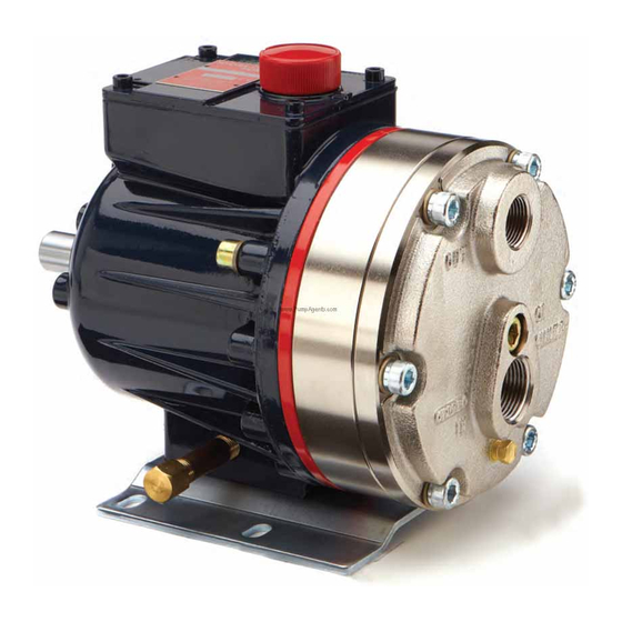
Models:
D-10 and G-10
W0215B
WANNER ENGINEERING, INC.
1204 Chestnut Avenue, Minneapolis, MN 55403
TEL: (612) 332- 5681 FA X: (612) 332- 6937
TOLL-FREE FAX [US only]: (800) 332-6812
www.hydra-cell.com
email: sales@wannereng.com
W0214B
Advertisement
Table of Contents


Need help?
Do you have a question about the D-10 and is the answer not in the manual?
Questions and answers
how to drain oil
To drain oil from a Hydra-Cell D-10 pump:
1. Remove the oil drain cap and allow all oil and contaminants to drain out.
2. Fill the reservoir with kerosene or solvent, manually turn the pump shaft to circulate the fluid, and then drain it.
- Caution: If using EPDM diaphragms or food-grade oil, do not use kerosene or solvents. Instead, flush with the same lubricant that is in the reservoir.
3. Repeat the flushing procedure if necessary.
4. Fill the reservoir with fresh oil and manually turn the pump shaft to circulate it.
This answer is automatically generated