Mono OMEGA PLUS Operating And Maintenance Manual
Including wirecut version depositor
Hide thumbs
Also See for OMEGA PLUS:
- Installation instructions manual (12 pages) ,
- Operating manual (72 pages)
Table of Contents
Advertisement
Quick Links
Advertisement
Table of Contents

Related Manuals for Mono OMEGA PLUS


Summary of Contents for Mono OMEGA PLUS
- Page 1 Enter Serial No. here. MANUAL No.Y-OM-03E In the event of an enquiry please quote this serial number. Store this document safely and ensure it is available at all times. Non-availability may affect the service / repair of your machine. OPERATING DEPOSITOR (400, 450,) 03/11...
- Page 3 Omega PLUS Failure adhere cleaning maintenance instructions detailed in this booklet could affect the warranty of this machine WIRECUT VERSION FOR SAFE WORKING, PAY SPECIAL ATTENTION TO ITEMS MARKED FG079 –OMEGA TOUCH INCL WIRECUT 03/11 RAC...
-
Page 4: Table Of Contents
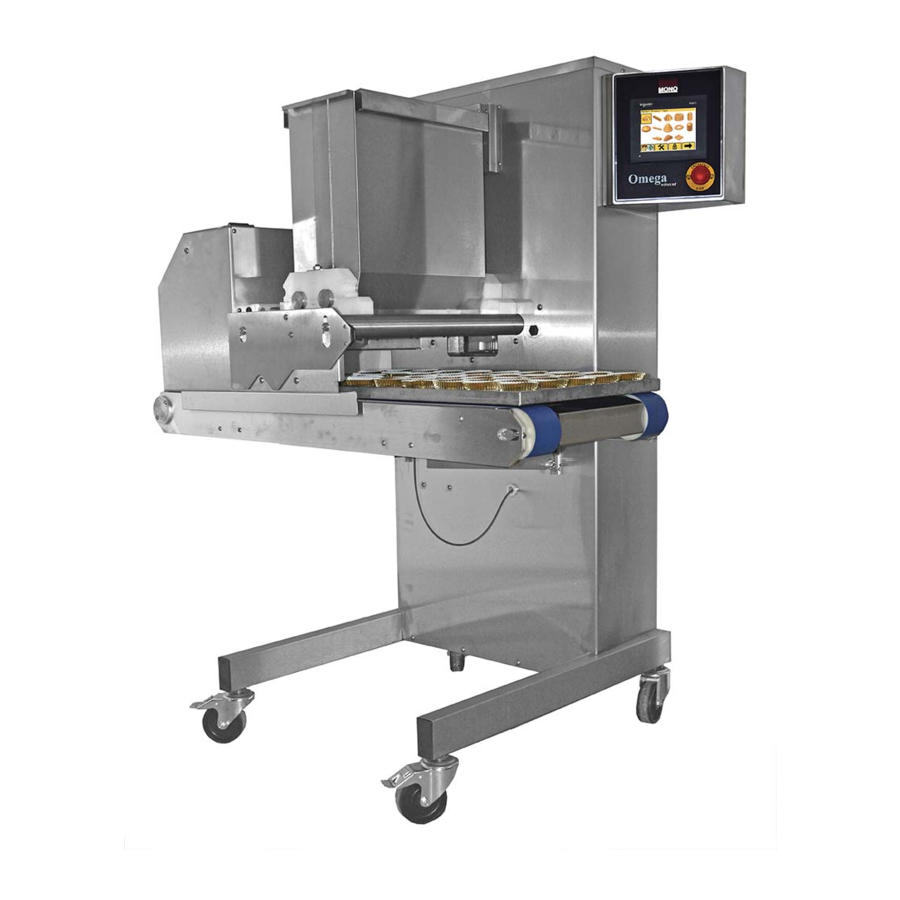
Omega CONTENTS PLUS INTRODUCTION DIMENSIONS SPECIFICATIONS SAFETY INSTALLATION ISOLATION CLEANING INSTRUCTIONS OPERATING CONDITIONS PREPARING FOR OPERATION 9A – FITTING THE HOPPER 9B – FITTING A TEMPLATE 10.0 OPERATING INSTRUCTIONS – SELECT PRODUCT TYPE – SELECT SAVED NAME OF PRODUCT TYPE –... - Page 5 PLUS • The innovative “five axis deposit” design of MONO’s “Omega PLUS” and “Omega PLUS with wirecut” depositor allows it to recreate most of the hand movements of the Master confectioner. This makes the “Omega PLUS” capable of exceptional accuracy of product weight, size and shape.
- Page 6 Omega 2.0 DIMENSIONS PLUS MODELS ARE AVAILABLE WITH OR WITHOUT WIRECUT OPTION 890mm WIRECUT 470mm 690mm 856mm 1210mm FG079 –OMEGA TOUCH INCL WIRECUT 03/11 RAC...
-
Page 7: Specifications
Viennese Sponge Drops However, consult Mono Equipment if intended product falls outside the above general machine specification to determine the exact capabilities of the “Omega” with any specific product. As it is our policy to improve our machines continuously, we reserve the right to change specifications without prior notice... -
Page 8: Safety
Omega 4.0 SAFETY PLUS Never use a machine in a faulty condition and always report any damage. Only trained engineers may remove parts that need a tool to remove them. Always ensure hands are dry before touching any electrical appliance (including cable, switch and plug). - Page 9 Omega PLUS 10 The bakery manager or the bakery supervisor should carry out daily safety checks on the machine. 11 Do not operate machine without hopper template and guard fitted correctly. (11) HOPPER TEMPLATE AND GUARD FITTED 12 Due to the essential requirement for handling heavy components during cleaning, it is recommended that protective footwear be worn when carrying out such procedures.
-
Page 10: Installation
Omega 5.0 INSTALLATION PLUS Ensure that the depositor is connected to correct electric supply, as specified on the serial number plate on the side of the machine. Ensure that the correct fuse rating is fitted in the electrical supply 6.0 ISOLATION IN AN EMERGENCY, SWITCH OFF AT THE ELECTRICAL MAINS WALL ISOLATOR, OR PUSH THE EMERGENCY STOP BUTTON. -
Page 11: Cleaning Instructions
Omega PLUS 7.0 CLEANING INSTRUCTIONS NOTE: - Cleaning must be carried out by fully trained personnel only. - Isolate machine from mains supply before carrying out any cleaning. - Do not steam clean or use a jet of water. -Do not use any form of caustic detergent or abrasive cleaners. - All the outer surfaces of the machine should be wiped over daily with warm soapy water. - Page 12 Slacken template clamp strip nuts or thumbscrews (depending on type of hopper) Remove fitted template from pump assembly by sliding out to avoid subsequent damage. NOTE. Thumbscrews only need to be released slightly to allow the template to slide away from the pump assembly.
- Page 13 Omega SOFT DOUGH HOPPER PLUS CAUTION: The feed hopper and pump assembly exceeds 25kg and will need to be lifted off by two people, or dismantled into smaller components while still on the machine. Take care to avoid damage to the sealing surface of the feed hopper during removal, cleaning, assembly and storage.
- Page 14 Omega HARD DOUGH HOPPER PLUS CAUTION: The feed hopper and pump assembly exceeds 25kg and will need to be lifted off by two people, or dismantled into smaller components while still on the machine. To reduce weight and bulk, separate and remove empty feed hopper from pump assembly, whilst still on the machine, by unscrewing the wing nuts.
-
Page 15: Operating Conditions
Omega OPERATING CONDITIONS PLUS To obtain the best product results and consistent operation, Make sure the depositor is used on a level floor. Ensure flat trays of consistent length, width, material and edge dimensions are used. Ensure undamaged nozzles and templates are used. Keep the machine clean. -
Page 16: Preparing For Operation
Omega 9.0 PREPARING FOR OPERATION PLUS Select template and nozzles (and finger frame, if wirecut is to be used) and fit as section 9a & 9b (following pages). Fill hopper with mix and close hopper cover. It is recommended that when heavy mixes are used, the inside of the hopper should be coated with vegetable oil;... -
Page 17: Fitting The Hopper
Omega FITTING THE HOPPER PLUS CAUTION SHOULD BE TAKEN WHEN FITTING THE HOPPER AND PUMP ASSEMBLY, AS WEIGHT EXCEEDS 25kgs ON SOME MODELS It will need to be lifted on by two people, or dismantled into smaller components before fitting on the machine. MAKE SURE THE FLOOR AREA AROUND THE MACHINE IS CLEAN To reduce weight and bulk, fit the complete hopper assembly in two stages - first the pump assembly onto the support bars, then the feed hopper body onto the pump... -
Page 18: Fitting A Template
Omega FITTING A TEMPLATE PLUS • Soft dough Non-rotary templates can be fitted with nozzles. This requires screwing the nozzles into the threaded holes provided. Rotary templates can have plastic nozzles screwed into nozzle holders (straight or offset). Metal nozzles secured in place by a separate nut. Select template and nozzles required. - Page 19 • Hard dough Non-rotary templates that can be fitted with nozzles, require them to be secured in place with a separate nut. Nozzles are not required for sheeting or wirecut templates. Rotary templates require nozzles to be secured in place with a separate nut. Select wirecut template or template and nozzles required.
- Page 20 IF WIRECUT FITTED FITTING WIRECUT FINGERS Select wirecut fingers that suit the chosen template to be used.i.e. the correct number to match the number of dies across template. Remove drop arm pins and insert finger frame into arms. Ensure that the follower arm roller is positioned on the cam track.
- Page 21 IF WIRECUT FITTED REPLACING BROKEN WIRE MAKE SURE THAT ALL PIECES OF WIRE HAVE BEEN FOUND BEFORE OPERATING MACHINE AFTER A WIRE REPLACEMENT. Remove fingers from the machine. Remove broken wire Feed new wire round screw between washers and tighten screw. Feed the wire through the eyehole in the end of each finger.
- Page 22 Omega PLUS FG079 –OMEGA TOUCH INCL WIRECUT 03/11 RAC...
- Page 23 FOLLOW BLUE ARROWS AND BOXES TO BLUE OPERATION OPERATE THE DEPOSITOR WITH ALREADY SAVED PROGRAMS FOLLOW RED ARROWS AND BOXES TO CHANGE SETTINGS CHANGE SETTINGS AND CREATE NEW PROGRAMS WHEN KEYBOARD APPEARS, A CODE KEYBOARD ENTRY MUST BE ENTERED BY TOUCHING THE REQUIRED NUMBERS IN THE CORRECT ORDER IF A GREY BOX IS SHOWN IN THE BUTTON DESCRIPTION...
-
Page 24: Select Product Type
SELECT PRODUCT TYPE TO CREATE A NEW PROGRAM SELECT PRODUCT TO DEPOSIT TOUCH THE SCREEN FOR THE TYPE OF PRODUCT REQUIRED THEN TO MOVE TO THE NEXT SCREEN STRIP WITH MULTIDROP MULTIDROP TWIST WITH TWIST HIGHLIGHT BOX SPIRAL APPEARS TO SHOW SELECTED PRODUCT WHEN SCREEN IS TOUCHED... -
Page 25: Select Saved Name Of Product Type
SELECT SAVED PRODUCT TYPE CHOOSE EMPTY SLOT TO CREATE A NEW PROGRAM PAGE NUMBER PAGE BACK PAGE FORWARD BEING DISPLAYED PROGRAM NAME (USER DEFINED) MOVE UP LIST EMPTY SLOT USED TO CREATE NEW PROGRAM TYPE OF PRODUCT THIS SCREEN APPLIES TO MOVE DOWN LIST RETURN TO NEXT... -
Page 26: Confirm Setup
CONFIRM SETUP OF MACHINE MACHINE MUST BE SET AS SHOWN ON THE SCREEN. THEN PRESS CONFIRM BUTTON. PROGRAM NAME (CHOSEN ON PREVIOUS SCREEN) TEMPLATE TYPE NON-ROTARY ROTARY NOZZLE NUMBER RETURN TO LAST CONFIRM MACHINE SETUP. SCREEN WARNING TO AVOID MACHINE DAMAGE ONLY PRESS WHEN ALL SETTINGS SHOWN ARE CORRECT TEMPLATE... -
Page 27: Operator Screen
OPERATOR SCREEN MACHINE IS SET AS SHOWN ON THE SCREEN. THIS SCREEN CONTROLS THE ACTIONS REQUIRED BY THE OPERATOR. HOPPER TYPE SOFT DOUGH HARD DOUGH PROGRAM NAME WEIGHT VALUE WEIGHT VALUE ADJUSTMENT TEMPLATE TYPE NOZZLE NUMBER NON- ROTARY TEMPLATE NUMBER ROTARY RETURN PRIME PUMP... - Page 28 EDIT AND SAVE SCREEN PROGRAM NAME PRODUCT QUANTITY MUST BE ENTERED TO THIS IS A SETTING NUMBER AND ALLOW PROGRAM TO SAVE DOES NOT INDICATE A MEASURE OF ACTUAL VOLUME DROP WITH TWIST NOZZLE ROTATIONS NOZZLE HEIGHT (mm) NUMBER OF TURNS ABOVE TRAY SURFACE DURING A DEPOSIT CYCLE MAX HEIGHT FOR...
- Page 29 SETTING ERROR INDICATOR BOXES TURN RED WHEN INCORRECT SETTING MADE DEPOSIT QUANTITY FOR EACH LAYER NOZZLE HEIGHT (mm) NUMBER OF TURNS FOR EACH LAYER FOR EACH LAYER (-VE VALUES POSSIBLE) NOZZLE HEIGHT (mm) FROM TRAY SURFACE OTHER SETTING BUTTONS ARE THE SAME AS LAST PAGE PRIME PUMP (HARD DOUGH SHOWN)
- Page 30 " DEPOSIT QUANTITY FOR END OF DEPOSIT QUANTITY PRODUCT DURING ROTATION (-VE VALUES POSSIBLE) RADIUS (mm) NOZZLE HEIGHT OF DEPOSIT ABOVE TRAY SURFACE NOZZLE ROTATION (NUMBER OF TURNS DURING DEPOSIT) DEPOSIT QUANTITY FOR BEGINNING OF PRODUCT (-VE VALUES POSSIBLE) RED TRAY SETUP BUTTON FORCES USER TO ENTER AND CHECK TRAY SETUP VALUES (OTHER BUTTONS GREYED OUT)
-
Page 31: Tray Setup
TRAY SETUP PRESS WINDOWS AND ENTER VALUES VIA KEYPAD DISTANCE (mm) TO 1 ROW ON TRAY (WHEN USING MANUAL OVER-RIDE) DISTANCE (mm) BETWEEN ROWS (WHEN USING MANUAL OVER-RIDE) MANUAL OVER-RIDE FOR ROW SPACING DIRECTION OF TRAY ON/OFF MOVEMENT TRAY EDGE NUMBER OF HEIGHT (mm) ROWS PER... -
Page 32: Copy
COPY HIGHLIGHT PROGRAM TO MOVE HIGHLIGHT UP COPY MOVE HIGHLIGHT DOWN PRESS COPY ENTER PROGRAM LIST POSITION REQUIRED TO COPY TO. PRESS “OK” CONFIRM “COPY TO” POSITION IS CORRECT PRESS “OK” PROGRAM DETAILS ARE COPIED TO NEW LOCATION FG079 –OMEGA TOUCH INCL WIRECUT 03/11 RAC... -
Page 33: Delete
DELETE HIGHLIGHT PROGRAM TO MOVE HIGHLIGHT UP DELETE MOVE HIGHLIGHT DOWN PRESS DELETE TO CONFIRM, “DELETE” IS CORRECT PRESS “OK” FG079 –OMEGA TOUCH INCL WIRECUT 03/11 RAC... -
Page 34: Passwords
PASSWORDS CAUTION CAUTION DO NOT ATTEMPT TO MAKE ADJUSTMENTS UNLESS YOU ARE DO NOT ATTEMPT TO MAKE ADJUSTMENTS UNLESS YOU ARE FULLY FULLY AWARE OF THE RESULTS AWARE OF THE RESULTS 1111 2222 EDIT/COPY EDIT/COPY DELETE 561234 1234 – SCREEN ADJUSTMENT CHANGE EDIT/COPY PASSWORD... - Page 35 ENGINEERING SETTINGS THIS SECTION IS FOR TRAINED ENGINEERS ONLY IN MANUAL MODE: DISTANCE THE LEADING EDGE OF THE TRAY IS BROUGHT BACK PASSED THE TRAY SENSOR, WHEN RETURNING TO OPERATOR SPEED VALUE THAT TRAY IS FED UP TO TRAY SENSOR EXIT GO TO NEXT SCREEN THIS SCREEN...
-
Page 36: Engineering Settings
ENGINEERING SETTINGS THIS SECTION IS FOR TRAINED ENGINEERS ONLY DEFAULT TRAY SPEED (MOVEMENT BETWEEN ROWS) DEFAULT JOG SPEED (VERTICAL AFTER DEPOSIT) DEFAULT SPEED OF PUMP (100% VALUE IN PRODUCT SETUP PROGRAM) DEFAULT ACCELERATION FOR PUMP DEFAULT ACCELERATION FOR JOG DEFAULT ACCELERATION FOR TRAY PUMP SPEED... - Page 37 ENGINEERING SETTINGS THIS SECTION IS FOR TRAINED ENGINEERS ONLY OFFSET HEIGHT VALUE IS FACTORY SET AND SHOULD NOT BE CHANGED UNLESS INSTRUCTED TO DO SO. OFFSET HEIGHT VALUE (mm) DAMAGE TO THE MACHINE HARD DOUGH HOPPER COULD OCCUR NON-ROTARY TEMPLATE OFFSET HEIGHT VALUE (mm) HARD DOUGH HOPPER ROTARY TEMPLATE...
- Page 38 ENGINEERING SETTINGS THIS SECTION IS FOR TRAINED ENGINEERS ONLY GEARBOX RATIOS PUMP TRAY ROTARY EXIT THIS SCREEN GO TO PREVIOUS SCREEN GO TO NEXT SCREEN ENGINEERING SETTING 3 ENGINEERING SETTING 5 (PREVIOUS PAGE) (NEXT PAGE) CAUTION DO NOT ATTEMPT TO MAKE ADJUSTMENTS UNLESS YOU ARE FULLY AWARE OF THE RESULTS FG079 –OMEGA TOUCH INCL WIRECUT 03/11 RAC...
- Page 39 ENGINEERING SETTINGS THIS SECTION IS FOR TRAINED ENGINEERS ONLY WIPE BACK DEFAULT SETTINGS (SEE 5A ) TRAY SPEED ROTARY SPEED JOG SPEED EXIT GO TO NEXT SCREEN THIS SCREEN FOR WIRECUT OPTIONS (IF WIRECUT FITTED) GO TO PREVIOUS SCREEN ENGINEERING SETTING 4 NEXT (PREVIOUS PAGE) SCREEN...
- Page 40 WIRECUT SETTINGS HARD DOUGH OFFSET WIRECUT SPEED + ECCELERATION WIRECUT GEARBOX RATIO EXIT THIS SCREEN GO TO PREVIOUS SCREEN ENGINEERING SETTING 4 (PREVIOUS PAGE) FG079 –OMEGA TOUCH INCL WIRECUT 03/11 RAC...
-
Page 41: Fault Information Screens
FAULT INFORMATION SCREENS WIRECUT COVER HOPPER COVER SAFETY BEAM STOP BUTTON (IF FITTED) THIS SCREEN INDICATES A FAULT CONDITION IN THE SAFETY AREAS. WHEN RED, CLOSE COVER OR CLEAR OBSTRUCTIONS TO CLEAR FAULT. WHEN INDICATOR GOES GREEN, FAULT HAS BEEN CORRECTED AT THAT POSITION. PRESS BUTTON TO CLEAR SCREEN CAUTION... - Page 42 IF THE FOLLOWING SCREEN APPEARS, CHECK THAT THE TABLE MOVEMENT ETC. IS NOT JAMMED WITH SOMETHING. I F IT IS, CLEAR THE OBSTRUCTION AND PRESS TO PROCEED. PRESS THIS BUTTON IF MORE INFORMATION REQUIRED AS TO WHICH MOTOR IS AT FAULT IF THE FAULT IS NOT OBVIOUS AND NOT ABLE TO BE CLEARED SAFELY, A SUITABLY TRAINED ENGINEER SHOULD BE CALLED ERROR WHEN LOADING/SAVING RECIPE DATA TO HMI STORAGE CARD...
-
Page 43: Maintenance
Omega PLUS 11.0 MAINTENANCE Under most conditions the machine only needs to be kept clean and used as instructed in this manual. WARNING: DO NOT UNDER ANY CIRCUMSTANCES USE A WATER HOSE OR PRESSURE WASHER TO CLEAN THIS MACHINE. FG079 –OMEGA TOUCH INCL WIRECUT 03/11 RAC... -
Page 44: Spares And Service
Omega PLUS 12.0 SPARES AND SERVICE If a fault arises, please do not hesitate to contact the Customer Service Department, quoting the machine serial number on the silver information plate of the machine and on the front cover of this manual... - Page 45 Omega PLUS 13.0 SPARES OMEGA PLUS (INCLUDING WIRECUT VERSION) FG079 –OMEGA TOUCH INCL WIRECUT 03/11 RAC...
- Page 46 OMEGA PLUS WIRECUT VERSION ELECTRICAL COMPONENT LAYOUT PARTS SAFETY RELAY B801-11-019 RELAY B801-37-001 36V PSU BASE B801-36-001 24V PSU LMC 20 B782-93-001 B801-93-005 B801-80-035 B872-22-102 B872-22-006 B801-94-009 B872-22-003 HMI CF CARD HOPPER GUARD SWITCH B801-80-017 B818-07-017 DEPOSIT MOTOR DRIVE WIRECUT MOTOR...
- Page 47 OMEGA PLUS WIRECUT VERSION MECHANICAL COMPONENT LAYOUT PARTS DEPOSIT DRIVE SHAFT SEAL A900-12-079 SLIDE PLATE V-SLIDE 078-03-00027 M078-03-00016 THUMBSCREW P700-04-018 IDLE SPROCKET A900-07-072 CONVEYOR BELT A900-22-120 BEARING- DRIVE SHAFT A900-06-277 BEARING – IDLE ROLLER A900-06-261 NYLON WASHER – IDLE ROLLER...
- Page 48 OMEGA PLUS WITHOUT WIRECUT MECHANICAL COMPONENT LAYOUT PARTS DEPOSIT DRIVE SHAFT SEAL A900-12-079 SLIDE PLATE V-SLIDE 078-03-00027 M078-03-00016 THUMBSCREW P700-04-018 IDLE SPROCKET A900-07-072 CONVEYOR BELT A900-22-120 BEARING- DRIVE SHAFT A900-06-277 BEARING – IDLE ROLLER A900-06-261 NYLON WASHER – IDLE ROLLER...
- Page 49 OMEGA PLUS WITHOUT WIRECUT ELECTRICAL COMPONENT LAYOUT PARTS SAFETY RELAY B801-11-019 RELAY B801-37-001 LMC 20 24V PSU BASE B801-36-001 36V PSU B801-80-035 B782-93-001 B801-93-005 B872-22-102 B872-22-006 B801-94-009 B872-22-003 HMI CF CARD B801-80-017 HOPPER GUARD SWITCH DEPOSIT MOTOR DRIVE B818-07-017 B781-80-002...
- Page 50 Omega PLUS BASE MACHINE SPARES LIST (with wirecut) Spares Item Description Mono Part No. Qty Req. per M/C Deposit Gearbox A900-11-097 Jog Gearbox A900-11-092 Rotary Gearbox A900-11-091 Tray Gearbox A900-11-091 Concentric Guide Roller A900-06-274 Eccentric Guide Roller A900-06-273 V Slide...
- Page 51 Omega PLUS HARD DOUGH HOPPER PARTS HOPPER FABRICATION STANDARD CAPACITY M078-09-00086 (400mm) M078-09-00042 (450mm M078-09-00089 (580mm) EXTENDED CAPACITY M078-09-00087 (400mm) UPPER END BLOCK M078-09-00088 (450mm) (DRIVE SIDE) M073-09-00092 (580mm) M078-09-00036 WINGNUT A900-04-147 UPPER END BLOCK (DRIVEN SIDE) M078-09-00037 LOWER END BLOCK...
- Page 52 Omega PLUS SOFT DOUGH HOPPER PARTS HOPPER FABRICATION STANDARD CAPACITY M078-09-00008 (400mm) M078-09-00001 (450mm M078-09-00046 (580mm) EXTENDED CAPACITY M073-09-00200 (400mm) M073-09-00202 (450mm) M073-09-00203 (580mm) WINGNUT A900-04-043 HOPPER SEAL A900-12-083 (400mm) A900-12-084 (450mm) A900-12-085 (580mm) DRIVEN GEAR M073-09-00702 (400mm) M073-09-01602 (450mm)
- Page 53 Omega PLUS 14.0 ELECTRICAL INFORMATION FG079 –OMEGA TOUCH WIRECUT 03-11 RAC...
- Page 54 FG079 –OMEGA TOUCH WIRECUT 03-11 RAC...
- Page 55 FG079 –OMEGA TOUCH WIRECUT 03-11 RAC...
- Page 56 FG079 –OMEGA TOUCH WIRECUT 03-11 RAC...
- Page 57 FG079 –OMEGA TOUCH WIRECUT 03-11 RAC...
- Page 58 FG079 –OMEGA TOUCH WIRECUT 03-11 RAC...
- Page 59 FG079 –OMEGA TOUCH WIRECUT 03-11 RAC...
- Page 60 FG079 –OMEGA TOUCH WIRECUT 03-11 RAC...
- Page 61 FG079 –OMEGA TOUCH WIRECUT 03-11 RAC...
- Page 62 FG079 –OMEGA TOUCH WIRECUT 03-11 RAC...
- Page 63 FG079 –OMEGA TOUCH WIRECUT 03-11 RAC...
- Page 64 FG079 –OMEGA TOUCH WIRECUT 03-11 RAC...
- Page 65 FG079 –OMEGA TOUCH WIRECUT 03-11 RAC...
- Page 66 FG079 –OMEGA TOUCH WIRECUT 03-11 RAC...
- Page 67 The equipment mentioned in this manual has CE accreditation. As it is our policy to improve our machines continuously, we reserve the right to change specifications without prior notice Omega PLUS Omega PLUS And WIRECUT Queensway, Swansea West Industrial Estate, Swansea.
Need help?
Do you have a question about the OMEGA PLUS and is the answer not in the manual?
Questions and answers