Advertisement
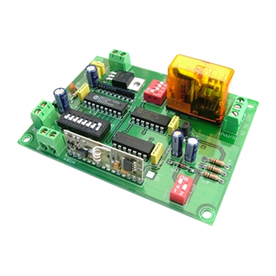
The remote receiver decodes the signals sent by the emitters Cebek TL- 20 , TL -21, TL- 28 , TL -29, TL- 30 , TL -31, TL- 38, TL- 39 , TL- 42 and with
which is only compatible , connecting the corresponding output.
Supports set the output monostable or bistable mode .
Includes indicator LED , relay output , terminal connection .
POWER : 12 VDC power supply we recommend Cebek FE-103/FE-2 , that fits perfectly the needs of the circuit.
Install a fuse and a switch to the protection and safety , as reflected in the CE standard.
A positive and negative to the corresponding input terminal .
ANTENNA INSTALLATION : Requires an antenna to emit with maximum power and efficiency . Must be installed before operating the remote , we
recommend the antenna Cebek C - 0509 and C - 0510 cable or 170 mm .
OUTPUT CONNECTION . LOAD : The output is via a relay device that supports any type of load does not exceed 5 A. The relay is a component that
provides voltage , but its role is limited to give way or cut the electrical flow that is introduced in the same way that occurs in a common switch .
Therefore, to supply the load through this device.
The relay has three output terminals : the Common , the rest normally open (NO ) and normally closed quiescent (NC ) . Install it between the
Common and the NO. Additionally , you can perform the inverse function , place the load between the Common and the NC .
Le récepteur de télécommande décode les signaux émis par les émetteurs Cebek TL- 20 , TL- 21 , TL- 28 , TL- 29 , TL- 30 , TL- 31 , TL- 38 , TL- 39 ,
TL- 42, et avec qui est uniquement compatible , reliant la sortie correspondante .
Prise en charge de définir le mode monostable ou bistable sortie .
Inclut indicateur LED, sortie relais , connexion terminal.
ALIMENTATION: 12 VDC , nous recommandons Cebek FE-103/FE-2 , qui est bien adapté aux besoins du circuit.
Installez un fusible et un interrupteur pour la protection et la sécurité , comme en témoigne la norme CE.
Un positif et négatif à la borne d'entrée correspondante .
INSTALLATION ANTENNE : Nécessite une antenne pour émettre avec une puissance et une efficacité maximale. Doit être installé avant d'utiliser la
télécommande, nous vous recommandons l'antenne Cebek C- 0509 et C- 0510 câble ou 170 mm .
CONNEXION DE LA SORTIE . CHARGE : La sortie se fait via un dispositif de relais qui prend en charge tout type de charge ne d épasse pas 5 A. Le
relais est un composant qui fournit une tension , mais son rôle est limité pour laisser place ou couper le flux électrique qui est introduit de la même
manière que se produit dans un commutateur commun . Par conséquent, pour alimenter la charge à travers ce dispositif .
Le relais dispose de trois terminaux de sortie : le commun , le reste normalement ouvert (NO) et normalement fermés au repos (NC) . Installez la
charge entre le Commun et le NO. En outre , vous pouvez exécuter la fonction inverse , placez la charge entre le Commun et le NC .
El Telemando receptor, decodifica las señales enviadas por los emisores Cebek TL-20, TL-21, TL-28, TL-29, TL-30, TL-31, TL-38, TL-39, y TL-42, con
los que es únicamente compatible, conectando la salida correspondiente.
Admite configurar la salida en modo Monoestable o Biestable.
Incorpora led indicador, salida relé, borne conexión.
ALIMENTACIÓN : de 12 V.C.C., le recomendamos fuente de alimentación Cebek FE-103/FE-2, que se adapta perfectamente a las necesidades del
circuito. Instale un fusible y un interruptor para la protección y seguridad, tal y como refleja la norma CE.
Una el positivo y el negativo a la correspondiente entrada del borne .
INSTALACION DE LA ANTENA : Precisa de una antena para poder emitir con el máximo de potencia y eficacia. Debe instalarse antes de hacer
funcionar el telemando, le recomendamos la antena Cebek C-0509 y la C-0510 ó un cable de 170 mm.
CONEXION DE LA SALIDA. CARGA : La salida se realiza mediante un relé, dispositivo que admite cualquier tipo de carga que no supere los 5 A. El
relé no es un componente que proporcione tensión, sino que su función se limita a dar paso o cortar el flujo eléctrico que le sea introducido, del
mismo modo que ocurre en un interruptor común. Por ello, deberá alimentar la carga a través de este dispositivo.
El relé dispone de tres terminales de salida: el Común, el Normalmente abierto en reposo (NO), y el Normalmente cerrado en reposo, (NC). Realice la
instalación entre el Común y el NO. Adicionalmente, podrá realizar la conexión inversa del relé, instalando la carga entre el Común y el NC.
Voltage. ......................................................12 V. D.C.
Minimum/Maximum Consumption. .............2 mA /65 mA.
Security Code combinations. .....................13.122.
Operating Frequency. ................................433,92 MHz.
Antenna Length. ........................................170 mm.
Max. Output Load by relay. ........................3 A.
Protection against inversion of polarity. ......Yes.
Sizes. ........................................................ 98,75 x 96 x 30 mm.
www.cebek.com
-
sat@cebek.com
R.F. Receiver
Récepteur R. F.
Receptor R.F.
1 Channel
TL-26
TECHNICAL CHARACTERISTICS
Advertisement
Table of Contents

Related Manuals for CEBEK TL-26


Summary of Contents for CEBEK TL-26
- Page 1 Common and the NO. Additionally , you can perform the inverse function , place the load between the Common and the NC . Le récepteur de télécommande décode les signaux émis par les émetteurs Cebek TL- 20 , TL- 21 , TL- 28 , TL- 29 , TL- 30 , TL- 31 , TL- 38 , TL- 39 , TL- 42, et avec qui est uniquement compatible , reliant la sortie correspondante .
- Page 2 W.), entre los dos contactos del relé utilizados en la conexión . SECURITY CODE CONFIGURATION : All Cebek remote controls work in the same frequency 433,92 MHz incorporate Therefore battery with 8 microswitches trinary switches , which lets you configure a custom security code .
- Page 3 TL-26 / 31 / 38 OPERATION : After selecting the security code number setting switch and all connections , turn on the power . The receiver lets you set the output for a monostable or bistable operation . In monostable mode , when you press the button on the transmitter , the output will be connected , staying connected only while the button is pressed, when released , the output is disconnected.
- Page 4 TL-26 GENERAL WIRING MAP. Outpunt 1 Switch Configuration Fuse 1A monostable / bistable Relay TL-26 FE-103 Outpunt 1 Aux output Antenna Alimentation www.cebek.com sat@cebek.com...
Need help?
Do you have a question about the TL-26 and is the answer not in the manual?
Questions and answers