Advertisement
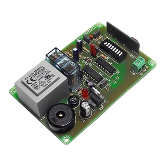
The TL-9 is a 1 channel remote control flip-flop receiver supplied by 230 VAC with relay output working by radiofrequency.
It will recognise the signal from TL-5 or TL-6 emitters, verify the security code and maintain the output connected until you
stop to press the push button of the emitter.
You could configure your own security code (between 13.122 possibilities) as well as to work with the TL-5 or the TL-6
Cebek emitters. It includes micro-switches to select the code, antenna output, led and acoustic signal for the
OPERATING
MODULE'S SUPPLYNG :
mains connect this last one to the input terminal 230 VAC. Install a fuse and a switch as it is indicated in General Wiring
Map (see hereafter). Both are necessary to protect the module and for your own security, as it is indicated in EEC
regulations. Then, verify that you have correctly connected the module.
Before to connect the module to the mains inserting voltage, please do the rest of connections specified hereafter. Do not
forget that in several part of the module there is voltage (230 VAC), for this reason we suggest you to be carreful.
OPERATING :
All CEBEK remote control works with a frequency adjusted at 433.92 MHz. For this reason, the TL-9
module includes micro-switches (SW-1) allowing to configure a security code between 13.122 possibilities, for each module.
Then, your module will be different from others, even if they offer same characteristics.
Seeing the drawing Nº1, you could note that the micro-switches SW-1 have 8 switches with three different positions. "-", "0"
and "+". You have to modify the switches position that you have received in order to select you personal code.
Do not forget. The receiver and emitter have to have the same se Once emitter and reciver are configurated with the
same code, you could supply the module. Then, press the push button on the emitter and the output will be connected till
you press again the button, to disconnect the output.
ANTENNA INSTALLATION :
Seeing the paragraph "General Wiring map", install a metallic antenna with a length of 130 mm. The cable between antenna
and module had to be shielded and inferior than 25 cm. Connect the negative terminal to the ground.
OUTPUT CONFIGURATION :
1 channel (TL-5 module), it also could be controlled by the TL-6 module 2 Channels emitter. Then, you have to select
between two push buttons the wished receiver output.
From the factory, the TL-9 module is supplied to be controlled by the TL-5 module (with 1 channel) with a single push button
closing the jumper JP1. Using the 2 channels emitter, you could check that you could connect the output with
RECEIVER REMOTE CONTROL
The Circuit TL-9 had to be supplied by 230 VAC. Using an adequate plug and a cable for
To obtain a maximum and clear reception, you have to install an exterior antenna.
Even if the receiver TL-9 had been developed to control its corresponding emitter with
www.cebek.com
1 CHANNEL FLIP-FLOP
TL-9
TECHNICAL CHARACTERISTICS
Voltage. .................................................230 V. AC.
Minimum Consumption. .......................15 mA.
Maximum Consumption. ......................55 mA.
Operating Frequency. ...........................433.92 Mhz.
Maximum Reach (approximately) . ......20 - 30 m.
Maximum Load at Output. ...................3 A.
-
info@cebek.com
Advertisement
Table of Contents

Related Manuals for CEBEK TL-9


Summary of Contents for CEBEK TL-9
- Page 1 From the factory, the TL-9 module is supplied to be controlled by the TL-5 module (with 1 channel) with a single push button closing the jumper JP1. Using the 2 channels emitter, you could check that you could connect the output with www.cebek.com...
- Page 2 OUTPUT CONNECTION. LOAD : The TL-9 output is controlled by a relay, and accept any device up to 3 A. The relay have three output terminals: The normally open quiescent (NO), the normally closed quiescent (NC) and the common. This mechanism operate like a switch with two terminals NO and Common.
Need help?
Do you have a question about the TL-9 and is the answer not in the manual?
Questions and answers