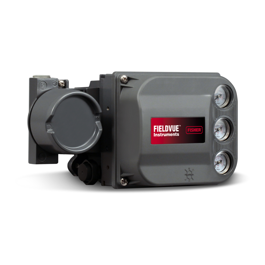
Emerson Fisher FIELDVUE DVC6200 Mounting Instructions
Digital valve controller on 657 and 667 size 30 60 actuators
Hide thumbs
Also See for Fisher FIELDVUE DVC6200:
- Quick start manual (44 pages) ,
- Instruction manual supplement (26 pages) ,
- Mounting instructions (8 pages)
Advertisement
Quick Links
Mounting Instructions
D103441X012
February 2012
Use these instructions to mount a Fisher
DVC6200 or DVC2000 digital valve controller on Fisher
657 and 667 size 30-60 actuators.
WARNING
Avoid personal injury or property damage
from sudden release of process pressure or
bursting of parts. Before performing any
maintenance operations:
D Always wear protective clothing,
gloves, and eyewear.
D Do not remove the actuator from the
valve while the valve is still pressurized.
D Disconnect any operating lines
providing air pressure, electric power, or a
control signal to the actuator. Be sure the
actuator cannot suddenly open or close
the control valve.
D Use bypass valves or completely shut
off the process to isolate the control valve
from process pressure. Relieve process
pressure from both sides of the control
valve.
D Vent the pneumatic actuator loading
pressure and relieve any actuator spring
precompression.
D Use lock‐out procedures to be sure
that the above measures stay in effect
while you work on the equipment.
D Check with your process or safety
engineer for any additional measures that
must be taken to protect against process
media.
Refer to figure 2 and the parts list for mounting parts
identification. Refer to the DVC6200 or DVC2000 digital
valve controller instruction manual for digital controller
parts identification. Refer to the appropriate actuator
instruction manual for actuator installation, operation,
maintenance, and parts identification.
1. Isolate the control valve from the process line pressure
and release pressure from both sides of the valve body.
Shut off all pressure lines to the actuator, releasing all
pressure from the actuator. Use lock‐out procedures to
be sure that the above measures stay in effect while you
work on the equipment.
www.Fisher.com
R
FIELDVUEt
657 and 667 Size 30‐60 Actuators
WARNING
To avoid personal injury due to the sudden,
uncontrolled movement of parts, do not
loosen the stem connector cap screws
when the stem connector has spring force
applied to it.
2. During the attachment of the connector arm (key 3)
to the valve stem connector it will be necessary to loosen
the stem connector cap screws. Consult the appropriate
actuator instruction manual for proper actuator
disassembly and reassembly. Install the connector arm
(key 3) when reassembling the stem connector assembly.
Leave the cap screws loose enough to allow side-to-side
adjustment.
Note
The stem connector imperial cap screws are the same
diameter as the metric hex head cap screws (key 1b) used to
mount the DVC6200 to the mounting bracket, but are NOT
interchangeable.
3. Attach the extension arm (key 6) to the connector arm
using two allen head screws (key 4) but do not tighten.
See figure 2 for extension arm orientation.
4. Attach the magnet assembly (key 5) to the extension
arm with two allen head machine screws (key 4) but do
not tighten (the magnet assembly can be inverted 180_
without effect).
5. Install the three hex head cap screws on the backside
of the mounting bracket and roll the O-rings on the
threads of the cap screws.
6. Attach the mounting bracket assembly (key 1) to the
yoke using the two socket head screws (key 2).
7. Attach the black plastic alignment template to the
mounting bracket by inserting the two protruding posts
into the mounting holes in the bracket and
simultaneously positioning the magnet assembly so that
it can slide into the channel in the alignment template.
The magnet assembly should be fully in the alignment
template channel so that the extension arm is contacting
the back of the alignment template but not bending it.
Tighten the stem connector assembly per the
appropriate actuator instruction manual. Tighten the
allen head screws (key 4), attaching the extension arm to
the connector arm but do not yet tighten the screws
attaching the magnet assembly.
8. For an air‐to extend actuator, slide the magnet
assembly (key 5) so that the bottom marking aligns with
DVC6200 or DVC2000
Digital Valve Controller on
Advertisement

Subscribe to Our Youtube Channel
Related Manuals for Emerson Fisher FIELDVUE DVC6200


Summary of Contents for Emerson Fisher FIELDVUE DVC6200
- Page 1 DVC6200 or DVC2000 Mounting Instructions Digital Valve Controller on D103441X012 657 and 667 Size 30‐60 Actuators February 2012 Use these instructions to mount a Fisher FIELDVUEt WARNING DVC6200 or DVC2000 digital valve controller on Fisher 657 and 667 size 30-60 actuators. To avoid personal injury due to the sudden, uncontrolled movement of parts, do not WARNING...
- Page 2 Fisher and FIELDVUE are marks owned by one of the companies in the Emerson Process Management business division of Emerson Electric Co. Emerson Process Management, Emerson, and the Emerson logo are trademarks and service marks of Emerson Electric Co. All other marks are the property of their respective owners.
Need help?
Do you have a question about the Fisher FIELDVUE DVC6200 and is the answer not in the manual?
Questions and answers