Advertisement
Quick Links
7929 Lincoln Ave. Riverside, CA 92504
Phone: 951.689.ICON
Fax: 951.689.1016
COMPONENTS INCLUDED
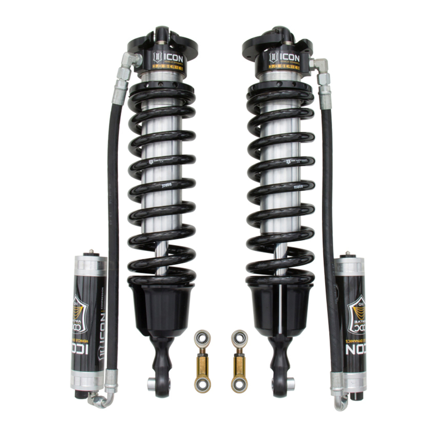
(1) 154970RCD 07+ TUNDRA 3.0 RR CDCV (DRVR)
HARDWARE INCLUDED
(2) 154006 07+ TUNDRA RESI MOUNT
(4) 159013 SLEEVE .750 X .563 X .125
(4) 159014 SLEEVE .750 X .563 X .375
(2) 295525 JM14MT PTFE MALE ROD END
(2) 295526 JF14MT PTFE FEMALE ROD END
(2) 605144 3/8-12 X .750 FLANGED SELF TAP
(2) 605812 M14-2.00 NYLOCK NUT
611025 COILOVER HARDWARE KIT
(8) 605101 3/8-16 X 1.000 HHCS
611051 HOSE CLAMP HARDWARE KIT
(4) 605931 1/2 X 2 1/16 - 3 #40 SS HOSE CLAMP
TOOLS REQUIRED
JACK
JACK STANDS
TORQUE WRENCH
DRILL
MARKER
11/32" DRILL BIT
11MM ALLEN WRENCH
BLACK SPRAY PAINT
TECH NOTES
1. YOUR ICON COILOVER ASSEMBLIES COME FACTORY CHARGED TO 150 PSI. RELEASING NITROGEN
PRESSURE MAY LEAD TO SHOCK MALFUNCTION AND REDUCED RIDE QUALITY. FAILURE CAUSED BY
LOW NITROGEN PRESSURE IS NOT COVERED UNDER ICON'S WARRANTY POLICY.
2. YOUR ICON COILOVER ASSEMBLIES COME SHIPPED AT ICON'S RECOMMENDED RIDE HEIGHT.
REDUCING DROOP TRAVEL WILL REDUCE RIDE QUALITY. DO NOT PRELOAD THE COIL BEYOND 1.25"
OF EXPOSED THREADS BETWEEN THE BOTTOM OF THE TOP CAP AND THE COIL ADJUSTER NUT.
ADJUSTING PRELOAD BEYOND THIS SETTING WILL CAUSE THE COIL TO BIND AND DAMAGE WILL
OCCUR TO COILOVER AND/OR VEHICLE.
3. THIS 3.0 COILOVER KIT MUST BE USED WITH AN ICON UPPER CONTROL ARM KIT. BILLET (58560)
OR TUBULAR (58460).
4. FAILURE TO TRIM SWAYBAR ENDS WILL RESULT IN SHOCK DAMAGE NOT COVERED UNDER
ICON'S WARRANTY POLICY.
5. FAILURE TO TRIM BUMPSTOP MOUNT WILL RESULT IN SHOCK DAMAGE NOT COVERED UNDER
ICON'S WARRANTY POLICY.
INSTALLATION
1
. While the truck is still on the ground, remove the sway bar links using a 19mm.
2
. Using a properly rated jack, raise the front of the vehicle and support the frame rails with jack stands. Ensure the jack stands are
secure and set properly before lowering the jack. NEVER WORK UNDER AN UNSUPPORTED VEHICLE. Remove the front wheels.
3
. Remove the factory skid plate using a 12mm. [FIGURE 1]
FIG.1
4
. Remove the sway bar using a 17mm. [FIGURE 2]
(1) 154970RCP 07+ TUNDRA 3.0 RR CDCV (PASS)
58755H HARDWARE KIT
(2) 605847 M14-2.0 JAM NUT
(2) 605848 M14-2.0 X 50MM SOCKET SCREW
(4) 605926 ZIP TIE
(2) 605936 ADEL CLAMP VINYL COATED .400"
(2) 605937 PINCH CLAMP 15/16 – 1 1/16
(1) 611025 07+ TUNDRA CO HARDWARE KIT PAIR
(1) 611051 STAINLESS STEEL HOSE CLAMP KIT
(8) 605131 3/8" SPLIT LOCK WASHER
ANGLE GRINDER W/ CUTOFF WHEEL
5/16" SOCKET / WRENCH
9/16" SOCKET / WRENCH
12MM SOCKET / WRENCH
17MM SOCKET / WRENCH
19MM SOCKET / WRENCH
22MM SOCKET / WRENCH
24MM SOCKET / WRENCH
58755 INSTALLATION INSTRUCTIONS
PART #
07-UP TUNDRA 3.0 VS RR CDCV
58755
** READ ALL INSTRUCTIONS THOROUGHLY FROM START TO FINISH
BEFORE BEGINNING INSTALLATION! IF THESE INSTRUCTIONS ARE
NOT PROPERLY FOLLOWED SEVERE FRAME, SUSPENSION AND TIRE
DAMAGE MAY RESULT TO THE VEHICLE!
** ICON VEHICLE DYNAMICS RECOMMENDS THAT YOU EXERCISE
EXTREME CAUTION WHEN WORKING UNDER A VEHICLE THAT IS
SUPPORTED WITH JACK STANDS.
** ICON VEHICLE DYNAMICS RECOMMENDS ALL INSTALLTION TO
BE PERFORMED BY A PROFESSIONAL SHOP/SERVICE TECHNICIAN.
PRODUCT FAILURE CAUSED BY IMPROPER INSTALLATION WILL NOT BE
COVERED UNDER ICON'S WARRANTY POLICY.
DESCRIPTION
COILOVER KIT
WARNING!
4-20-2017 REV.B
FIG.2
1
Advertisement

Subscribe to Our Youtube Channel
Summary of Contents for ICON 58755
- Page 1 OCCUR TO COILOVER AND/OR VEHICLE. ** ICON VEHICLE DYNAMICS RECOMMENDS ALL INSTALLTION TO 3. THIS 3.0 COILOVER KIT MUST BE USED WITH AN ICON UPPER CONTROL ARM KIT. BILLET (58560) BE PERFORMED BY A PROFESSIONAL SHOP/SERVICE TECHNICIAN. OR TUBULAR (58460).
- Page 2 FIG.7 . Install new ICON coilover assembly: there are 7 threaded holes in the top of the upper shock mount, you will be using 4 of them. . Using a 9/16” socket/wrench, install upper mount with the hose pointing outward and towards the front using (4) of the supplied...
- Page 3 . Install shock bolt in the lower control arm: The lower shock mount has (1) long and (1) short spacer. Make sure the short spacer is oriented toward the rear of the vehicle. This will space the shock further rearward in the pocket to ensure adequate clearance for the shock rod end.
- Page 4 . Assemble sway bar links as shown and adjust length to 4.0” as a starting point. Depending on alignment specifications, you may need to adjust the sway bar links to a shorter length to gain adequate coil cup clearance. Cycle the suspension to ensure no contact. .
- Page 5 ICON VEHICLE DYNAMICS SHOCK ABSORBER WARRANTY This shock absorber has a 1 year warranty against any manufacturer’s defects. If a shock fails within the initial year of ownership, the shock must be shipped to ICON Vehicle Dynamics for inspection and service. If a shock is inspected and it has been determined the shock failed due to neglect, damage caused by improper installation or any other reason besides “normal wear and tear”, the owner of said shock is responsible for all service costs.

Need help?
Do you have a question about the 58755 and is the answer not in the manual?
Questions and answers