Table of Contents
Advertisement
Quick Links
Instructions
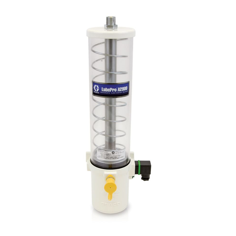
29:1 Lube Pro
Vertical Grease
Pump
For pumping non-corrosive and non-abrasive grease only. For professional use only.
Not approved for use in explosive atmospheres or hazardous locations.
Models:
See page 2 for model information, including maximum working
pressure and approvals.
3500psi (24 MPa, 241 bar) Maximum Working Pressure
175 psi (1.2 MPa, 12.07 bar) Maximum Air Input
Pressure
Important Safety Instructions
Read all warnings and instructions in this manual.
Save these instructions.
™
3A4096F
EN
Advertisement
Table of Contents

Subscribe to Our Youtube Channel
Related Manuals for Graco 29:1 Lube Pro


Summary of Contents for Graco 29:1 Lube Pro
- Page 1 Instructions ™ 29:1 Lube Pro Vertical Grease Pump 3A4096F For pumping non-corrosive and non-abrasive grease only. For professional use only. Not approved for use in explosive atmospheres or hazardous locations. Models: See page 2 for model information, including maximum working pressure and approvals.
- Page 2 Models Models Normally Normally Part No. Size Low Level Open Closed 24Z051 1 lb 24Z052 1 lb 24Z053 1 lb 24Z054 1 lb 24Z055 1 lb 24Z056 1 lb 24Z057 4 lb 24Z058 4 lb 24Z059 4 lb 24Z060 4 lb 24Z061 4 lb 24Z062...
-
Page 3: Electric Shock Hazard
Warnings Warnings The following warnings are for the setup, use, grounding, maintenance, and repair of this equipment. The exclama- tion point symbol alerts you to a general warning and the hazard symbols refer to procedure-specific risks. When these symbols appear in the body of this manual or on warning labels, refer back to these Warnings. Product-spe- cific hazard symbols and warnings not covered in this section may appear throughout the body of this manual where applicable. - Page 4 Warnings WARNING PLASTIC PARTS CLEANING SOLVENT HAZARD Many solvents can degrade plastic parts and cause them to fail, which could cause serious injury or property damage. • Use only compatible water-based solvents to clean plastic structural or pressure-containing parts. • See Technical Data in this and all other equipment instruction manuals.
-
Page 5: Personal Protective Equipment
Warnings WARNING PERSONAL PROTECTIVE EQUIPMENT Wear appropriate protective equipment when in the work area to help prevent serious injury, including eye injury, hearing loss, inhalation of toxic fumes, and burns. Protective equipment includes but is not limited to: • Protective eyewear, and hearing protection. •... -
Page 6: Typical Installation
Installation Installation Typical Installation . 1: Typical Installation Key: Main Air Supply Line Injector Filter/Regulator/Lubricator Assembly Lubricator controller B1 - Air Filter Pump reservoir B2 - Air Regulator Pump reservoir fill port B3 - Air Lubricator Ground Air solenoid valve (3-way) Pump air inlet - forward stroke Pump module Air outlet... - Page 7 Installation Grounding Mounting Grounding is necessary when voltages above 30 Mount the pump securely so that it cannot move VAC or 42 VDC are used for the low level switch or an around during operation. Failure to do so could result air valve is attached to the pump.
-
Page 8: Fill Reservoir
Installation Air and Fluid Line Accessories To use the air regulator reading to determine the fluid output pressure, multiply the ratio of the pump (29:1) Refer to F . 1, page 6, for the following instruction by the air pressure shown on the regulator gauge or see Table 1: Lubricant Output - PSI or Table 2: Lubri- Install the air line accessories in the order shown in F cant Output - MPa (bar), provided on page 13. - Page 9 Installation Priming 3. Slowly dispense grease from the fill pump into the reservoir until the grease in the reservoir lifts the fol- Refer to F . 1, page 6, for the following instruction lower plate (22) above the reservoir weep hole (wh), grease comes out of the weep hole (wh) and expels NOTE: the air inside the reservoir (F...
-
Page 10: Pressure Relief Procedure
Installation Pressure Relief Procedure Air Lock Procedure Follow the Pressure Relief Procedure whenever you see this symbol. The reference letters used in the following instructions refer to the Typical Installation F . 1 on page 6. An air lock occurs when a bubble or pocket of air pre- vents the normal flow of the lubricant. - Page 11 Installation • It may take up to 20 the pump strokes to expel the air from the pump and deliver a continuous flow of grease. This will depend on the viscosity of the lubricant and temperature. • Allow a minimum of 5 seconds ON time for the for- ward stroke and 5 seconds OFF time for the return stroke.
-
Page 12: Operation
Operation Operation Pump Low Level Switch Start Up As grease is dispensed, the follower plate (22) travels down the reservoir. When it gets close to the low level switch (lls) the magnet (28) on the bottom of the fol- lower plate assembly activates the normally closed low level switch;... - Page 13 Operation Lubrication System Sizing and Calculation Guidelines Table 1: Lubricant Output and Pressure - US NOTE: The lubricant output per pump stroke must be less than the amount of lubricant discharged per pump stroke. Injector Max Pump Maximum Minimum Pressure Recommended Pressure Volume to Lubricant...
-
Page 14: Seal Replacement
Repair Repair Seal Replacement NOTE: For most seal replacement procedures, the pump should be completely removed from service and clamped in a vise. If you are only replacing the reservoir and/or reservoir seals, you do not have to remove the pump from its service location. - Page 15 Repair 8. Clamp the pump base in a vise as shown in F . 12. 11. Remove reservoir (11) from the air motor cylinder Use a soft-jaw vise or place a rag in the vise jaws to (3) (F . 14). If replacing reservoir gaskets (10), protect the surface of the pump base.
- Page 16 Repair 12. Outlet Tube O-Ring (13) and Pump Cylinder 14. Remove o-ring (13) from outlet tube (14). Remove O-Ring (9) o-ring (9) from pump cylinder (12). Dispose of o-rings according to all regulations for proper dis- Securely hold nut (3a) [located on the bottom of the posal (F .
- Page 17 Repair 15. Pump Piston Subassembly (33) Secure a wrench on the flats of piston rod (34). Use a second wrench to remove lock nut (31) and star washer (32) from top of piston (F . 18). Remove lock nut and star washer. Keep these parts for reas- sembly.
- Page 18 Repair 19. Remove cover (1), cover o-ring (2) and spring (6). Dispose o-ring according to all regulations for proper disposal (F . 21). . 21 . 23 20. Piston Rod O-Ring (36) and Piston Seal (4) d. Dispose of piston seal (4) and o-ring (34a) and nut (37) according to all regulations for proper a.
- Page 19 Repair 22. Use a pick to remove the bushing (35) and u-cup seal (36) (F . 25). . 25 23. Use a smooth, long brass or aluminum rod, free of sharp edges and burrs, to push the check valve assembly (19) out of the outlet tube (14) (F .
- Page 20 Repair Reassembly 4. Piston Rod O-Ring (34a) and Piston Seal (4) Use all new part included in the repair / service kit even NOTE: Do not clamp piston rod (34) in vise. if the old parts do not appear to be worn or damaged and dispose of old parts according to all regulations for Use a clean cloth to wipe down the piston rod (34) proper disposal.
- Page 21 Repair 7. Install nut (37) over the end of the piston rod (34). Use two wrenches, working in opposite directions to tighten the nut. Secure one open end wrench to flats of piston rod and use the second wrench to tighten the nut as shown in F .
- Page 22 Repair 12. Reposition air motor cylinder in vise to access the 16. Outlet Tube O-ring (13) and Pump Cylinder top of air motor cylinder as shown in F . 35. O-ring (9) Apply a thin layer of grease to the outlet tube o-ring (13) and the pump cylinder o-ring (9) and install o-rings on the outlet tube (14) and pump cylinder (12) (F...
- Page 23 Repair 17. Install pump cylinder (12) in air motor cylinder (3). 19. Reservoir Gaskets (10) Use a wrench to tighten nut (3a) securely. 28 to 32 ft. lbs. (37.9 to 43.4 N.m). Install reservoir gaskets (10) to top and bottom of reservoir (11) as shown in F .
- Page 24 Repair 22. Install cover (18) on reservoir (11). Use your hand to apply pressure to the top of the cover and com- press the spring. At the same time, tighten and then torque nut (17) to 45 - 55 in. lbs. (5.1 to 6.2 N.m) .
-
Page 25: Troubleshooting
Troubleshooting Troubleshooting Problem Cause Solution Adjust air pressure/supply. No air Open bleed-type master air valve (F) (page 6). The pump is not operating. No lubricant No lubricant in reservoir Fill the reservoir. flow. Remove trapped air (see Air Lock, Losing prime page 10). - Page 26 Parts Parts Torque to 28 to 32 ft. lbs (37.9 to 43.4 N.m) Torque to 45 to 55 in. lbs (5.1 to 6.2 N.m) Torque to 25 to 30 in. lbs (2.8 to 3.4 N.m) Torque to 155 to 165 in. lbs (17.5 to 18.6 N.m) 3A4096F...
- Page 27 Parts Parts Part No. Description Part No. Description 118892 O-ring 17J825 COVER, Air motor ★ 17K560 HOLDER, magnet 17J826 SEAL, o-ring ★ 17K559 MAGNET, low level, models 17J828 CYLINDER, air motor, low level, 24Z052, 24Z053, 24Z055, models 24Z052, 24Z053, 24Z056, 24Z058, 24Z059, 24Z055, 24Z056, 24Z058, 24Z061, 24Z062 24Z059, 24Z061, 24Z062...
- Page 28 Dimensions Dimensions 3A4096F...
-
Page 29: Technical Data
Technical Data Technical Data LubePro 29:1 Vertical Grease Pump Metric Maximum fluid working pressure 3500 psi 24 MPa, 241 bar Fluid NLGI #00, 0, 1, 2 Pressure ratio 29:1 Pump output 0.58 cu. inch/stroke Reservoir capacity 1 lb (30 cu in.) or 4 lb (120 cu. in.) Maximum air inlet pressure 175 psi 1.20 MPa, 12.07 bar... -
Page 30: Graco Standard Warranty
With the exception of any special, extended, or limited warranty published by Graco, Graco will, for a period of twelve months from the date of sale, repair or replace any part of the equipment determined by Graco to be defective.
Need help?
Do you have a question about the 29:1 Lube Pro and is the answer not in the manual?
Questions and answers