
Related Manuals for DIG LEIT X Series


Summary of Contents for DIG LEIT X Series
- Page 1 LEIT® X and XRC Series Ambient Powered Irrigation Controllers Instruction Manual I N S T R U C T I O N M A N U A L...
-
Page 2: Table Of Contents
Table of ConTenTs A. Introduction ……………………………………………………………………… 3 B. About the LEIT X & XRC Controllers ………………………………………………… 3 C. Technical Assistance ……………………………………………………………… 3 D. Copyright and Compliance ………………………………………………………… 3 E. Features ………………………………………………………………………… 4 1. System ……………………………………………………………………………… 4 1.1 Models available ………………………………………………………………… 5 1.2 Parts identification ………………………………………………………………... -
Page 3: Introduction
The LEIT X and XRC use a time tested photovoltaic module, which harnesses light energy to generate electricity that is stored and used to power the controller day and night in any kind of weather. DIG LEIT irrigation controllers are available in two models: LEIT X (without radio) or LEIT XRC (with radio remote control capability). -
Page 4: Features
The user should make no field changes or modifications to the LEIT X, LEIT XRC Controller or the LEIT Link Remote Control Handset. All adjustments and changes must be made at DIG’s facility under the specific guidelines set forth in our manufacturing process. Any change or modification to the equipment will void the users authority to operate the unit, and render the equipment in violation of FCC part 15 subpart C, 15.247. -
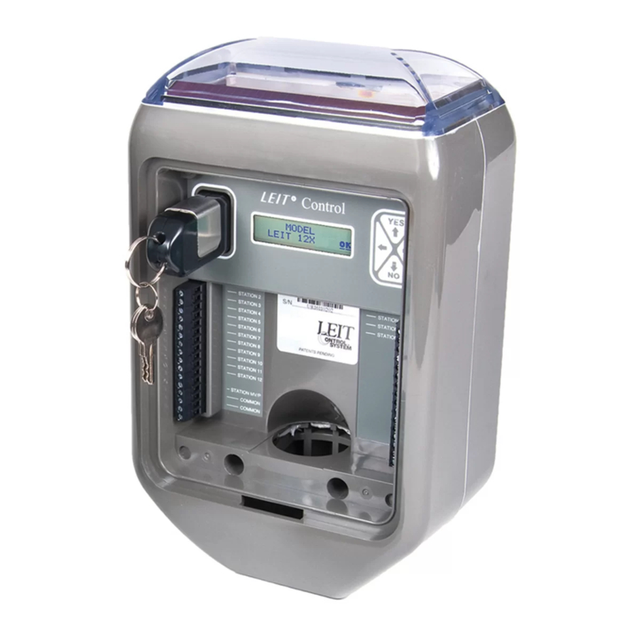
Page 5: Parts Identification
1.2 Parts Identification – Photovoltaic module harnesses light energy and use it to generates electricity to power the unit day and night in any kind of weather condition. LCD Display – Displays the application stored in the controller. Programming Buttons –... -
Page 6: Tools And Supply Requirements
7. Optional: Model SKIT 8821-4 connector: if any sensors are used, a SKIT 8821-4 adapter is required 8. Optional: Model RKIT 8810S relay: if pumps or any electrical equipment are used, an RKIT 8810S adapter is required 9. LEIT Link handset to communicate with a LEIT XRC controller 1.4 Tools and Supply Requirement 1. -
Page 7: Wire Installation And Distance
VALVE FOR LEIT CONTROLLER ASSEMBLY LEIT CONTR VALVE FOR LEIT CONTROLLER ASSEMBLY 18” VALVE BOX WITH COVER FINISH GRADE TOP DIG REMOTE CONTROL VALVE WITH FLOW CONTROL AND LEIT DC SOLENOID MODEL: 160HE-150 1-1/2” MODEL: 160HE-200 2” PVC SCH 40 MALE ADAPTER... -
Page 8: Sensor Installation
2. Run the field wires along their respective trenches from the valve box up to the bottom end of the mounting column. Make sure not to exceed the maximum recommended wire distance (see chart for maximum wire distance on page xxxx). -
Page 9: Pump Or Any Electrical Equipment Installation
sensor installation options OPTION 1 Sensor connected to controller using SKIT adapter DRY SPLICE WATERPROOF CONNECTORS OPTION 2 Sensor connected to a valve using SKIT adapter Figure B 4. pump or any eleCTrICal equIpmenT InsTallaTIon If it is required to switch ON a pump, fertilizer injector, fountain or light, two connection options are available using the RKIT 8810S relay interface module. - Page 10 InsTallaTIon LEGEND 1. “MINI CLIK” RAIN SENSOR. 2. DIG PLASTIC PIPE CAP – 1” CAP PART NO. 23-001 OR 1.5” CAP PART NO. 23-153 WITH HOLE FOR WIRES. 3. DRILL TWO 3/16 HOLES IN PIPE FOR SENSOR BRACKET. 4. (2) #8-32 MACHINE SCREWS WITH WASHER, LOCK WASHER AND NUT.
- Page 11 LEIT CONT LEGEND DRY SPLICE WATERPROOF CONNECTORS 18” VALVE BOX WITH COVER FINISH GRADE TOP DIG REMOTE CONTROL VALVE WITH FLOW CONTROL AND LEIT DC SOLENOID MODEL: 160HE-150 1-1/2” MODEL: 160HE-200 2” PVC SCH 40 MALE ADAPTER PVC MAIN LINE BRICK SUPPORT AT EACH CORNER PEA GRAVEL SUMP MINIMUM 3”...
-
Page 12: Programming
5. proGrammInG This chapter explains the controller buttons hierarchy and how to review, modify settings, program the controller, or to perform a manual run. To enter the controller, the user needs a LEIT Key or the LEIT Link handset (LEIT XRC). Insert the LEIT KEY into the controller key slot and follow the steps below. -
Page 13: Manual Run
5.1 MANUAL RUN Setting up a Manual Run The Manual Run is useful for checking the proper operation of MANUAL stations (especially after installation), for applying additional water as RUN? required, or for testing the valves. The first option available on the main menu is to perform a Manual Run. - Page 14 Start Manual Run? Press to start Manual Run (if within the spray area, remove the LEIT Key, replace and lock the LEIT Controller door to protect the controller). The LEIT Controller will start the manual run immediately, running each valve for the programmed duration that has been selected.
-
Page 15: Rain Stop/Restart
If Rain Stop is active it can be canceled manually anytime in the Cancel Rain Stop? Cancel Rain Stop screen. Once there, press l Yes underscore Yes and press to select. Press again to underscore OK. Press continue, this will bring back the Rain Stop screen. 5.3 MONTHLY BUDGET Setting a Monthly Budget MONTHLY... - Page 16 Prog:X Active This screen appears if any program or valve is active. Press Valve xx Open to continue. Prog:X Active This screen appears if any program or group of valves is active. GRPxx:yy Open Press to continue. Manrun Active This screen appears if a Manual Run is in progress. Press Valve:XX Open continue.
-
Page 17: History Reports
5.5 HISTORY REPORTS Review The Controller History Reports This feature allows the user to review the controller operating history HISTORY reports for a total watering time for each valve with overall total and REPORT? manual run total. This information is available for the current month and the previous 11 months. -
Page 18: Setup Schedule
5.6 SETUP SCHEDULE Review or change the Programming Schedule This feature allows the user to review, change or set a schedule with SET UP up to four separate programs for each station, each with up to three SCHEDULE? individual start times per day. It also allows the user to group stations together. - Page 19 SETTING START TIME 12:00 am In this screen select up to 3 start times per day (including AM Start or PM). To select the first start time underscore the appropriate digit using the . Then, press to increase to decrease the value of the appropriate digit. Repeat the steps again for each digit. When finished, press again to underscore OK.
-
Page 20: Setup System
Valve Runtime screen. Press and underscore the letter G located to left of the hour digit in the runtime screen to remove the letter G (group leader) from a group of valves. Press and the letter G will disappear. Repeat with the other valves as needed. Press again to underscore OK. - Page 21 Passwords screen provide the user a security against Password: AAA unauthorized changes being made to the system. The Default password is AAA. If the password has not been changed press to continue. If the password has been changed, enter the new password to continue. To change a password scroll to Change a Password screen at the end of Setup System.
- Page 22 controller to continue irrigation at any month of the year, simply add back the checkmark. Repeat the steps to activate or deactivate any additional months. Press again to underscore OK. Press continue. This screen tests the solenoids for shorts and/or open wires. Active CCT Test Short Open...
-
Page 23: Setup Radio (Leit Xrc Only)
then press to enter the station # that the sensor is connected to. Press again to underscore OK. Press to continue This screen, Sensor Governs, allows the user to designate the Sensor installed valves that will be governed by the sensor. To designate Governs: the valves that the sensor will control, press underscore the valve numbers to be governed by the sensor, then press... - Page 24 This screen allows the user to select one of two modes, Local Mode or Remote Mode. Local Mode: (default) The LEIT XRC controller is not listening to a signal from the LEIT Link handset and radio power is conserved. Remote Mode: Enables the LEIT XRC controller to scan for a signal from the LEIT Link handset.
-
Page 25: Help
Remote Mode communicating. In this case, wait a few minutes and repeat the set up radio process.. 5.9 HELP For customer support enter the help section and contact DIG at the telephone number listed HELP? To enter Help press Press to skip help and move to the next feature. -
Page 26: Leit Controller
4. If in doubt about the battery, install a new battery, or test the key with a multi-meter by holding the probes into the metal holes, voltage should be at least 8-volts DC. 5. The LEIT Key will work with all current and discontinued SOLATROL, ALTEC, and current LEIT controllers. 6.2 LEIT Controllers 1. -
Page 27: Hydraulic Valves
If any apparent defect arises under normal use and service in the LEIT product within the warranty period, DIG at its sole discretion, shall have the option to repair or replace part or all of the original product free of charge after return of such product at user expense, authorized in writing by DIG Corp. -
Page 28: Leit Control Programming Quick Reference Chart
8. leIT ConTrol proGrammInG quICk referenCe CharT...
Need help?
Do you have a question about the LEIT X Series and is the answer not in the manual?
Questions and answers