Table of Contents
Advertisement
Quick Links
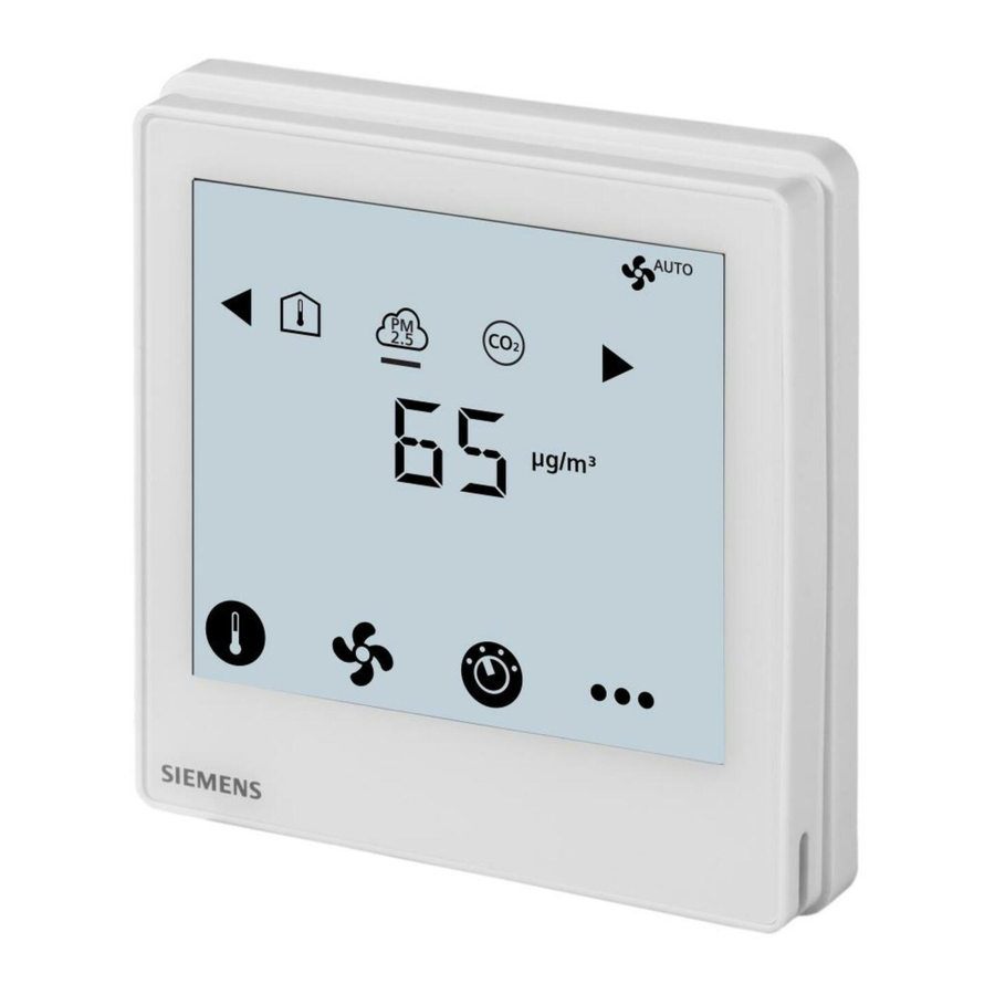
Touch Screen Flush-Mounted PM2.5 & IAQ Controllers With
KNX or RS485 Modbus
RDF870KN.. and RDF870MB..
PM2.5 control, CO2 control, or both and ventilation applications
RDF870KN (KNX) and RDF870MB (Modbus) controllers:
●
●
●
●
●
●
●
●
●
●
●
●
RDF870MB can be configured as a room unit via DIP switches and it provides the following
additional functions:
●
●
Mounting on recessed square 86 mm box or round 60 mm with 60 mm fixing centers and min-
imum 40 mm depth
A6V11439454_en--_d
2021-03-31
AC 230 V operating voltage, large, backlit display
Display and setpoint adjustment for PM2.5 and CO
Display of room temperature, outside temperature, VOC (volatile organic compound) and
r.h. (relative humidity)
Supports 1-/3-/4-speed On/Off fan or DC fan output
Two multifunctional inputs for external passive and DC 0...10 V sensors
Operating modes: Comfort, Economy and Protection
KNX S-Mode for RDF870KN
KNX commissioning via ETS or local control parameters
KNX integration into Desigo via group (ETS) or individual addressing
KNX integration into third-party system via group addressing (ETS)
RS485 Modbus RTU slave mode for RDF870MB
Modbus commissioning via third-party tool, e.g. Modbus scan, Modbus poll, etc.
Setpoint adjustment and display for room temperature, VOC, RH and display of outside
temperature
Four external outputs via bus and controlled by a master controller
control
2
Smart Infrastructure
Advertisement
Table of Contents

Related Manuals for Siemens RDF870KN Series


Summary of Contents for Siemens RDF870KN Series
- Page 1 Touch Screen Flush-Mounted PM2.5 & IAQ Controllers With KNX or RS485 Modbus RDF870KN.. and RDF870MB.. PM2.5 control, CO2 control, or both and ventilation applications RDF870KN (KNX) and RDF870MB (Modbus) controllers: ● AC 230 V operating voltage, large, backlit display ● Display and setpoint adjustment for PM2.5 and CO control ●...
-
Page 2: Mechanical Design
The room controller/room unit consists of the following parts: ● Front panel with electronics, operating elements and built-in room temperature sensor ● Mounting base with power electronics ● Mounting frame is an additional part to complete the installation for RDF870… Siemens A6V11439454_en--_d Smart Infrastructure 2021-03-31... - Page 3 Heating mode Alarm/service reminder Valve on Manual override Cooling mode Protection mode Ventilation mode Auxiliary heating active Auto fan mode Economy mode Timer Selection symbols Room temperature VOC mode Outdoor temperature mode PM2.5 mode Relative humidity Siemens A6V11439454_en--_d Smart Infrastructure 2021-03-31...
- Page 4 Room sensor for detection of QSA2700 A6V11160938 PM2.5 3-color LED service indication Room sensor with LCD QSA2700D A6V11160938 display for detection of PM2.5 2.4-inch color LCD screen for PM2.5 values, air quality index, and service Siemens A6V11439454_en--_d Smart Infrastructure 2021-03-31...
-
Page 5: Product Documentation
QPM2160, N1962 temperature / rel. humidity / QPM2180 Duct air quality sensor CO QPM2160D, N1962 temperature / rel. humidity / QPM2162D https://www.downloads.siemens.com/download- *) All documents can be downloaded from center. Product documentation Title Document ID: Operating instruction A6V11439451 CE declaration... -
Page 6: Mounting And Installation
When a KNX bus power supply is connected on the line with communicating room con- troller and Synco controllers, the internal KNX power supply of the Synco controllers must be switched off. (Only for RDF870KN) Siemens A6V11439454_en--_d Smart Infrastructure 2021-03-31... -
Page 7: Dip Switch Configuration
Current factory setting for PM2.5 control with 3 speed on/off fan application is as follows: ● APP= 1: PM2.5 control only ● DISP: Room temp= 1; PM2.5= 1 ● SEN1= 3: PM2.5 (AI) μg/m (0…10 V) ● SEN2= 0: no function ● FAN= 3: 3 speed fan Siemens A6V11439454_en--_d Smart Infrastructure 2021-03-31... -
Page 8: Warranty
Comply with all local and currently applicable laws and regulations. Warranty Technical data on specific applications are valid only together with Siemens products listed under "Equipment combinations". Siemens rejects any and all warranties in the event that third-party products are used. - Page 9 Maximum current 5(2) A ECM fan Type Modulating Voltage DC 0…10 V Maximum current 5.0 mA CAUTION If fans must be connected in parallel, connect one fan directly, for additional fans, one relay for each speed. Siemens A6V11439454_en--_d Smart Infrastructure 2021-03-31...
- Page 10 Transport as per EN 60721-3-2 Class 2M2. Operation as per EN 60721-3-3 Class 3M2. No condensation is allowed. Standards, directives and approvals For residential, commercial, and industrial Electromagnetic compatibility environments EU conformity (CE) A5W90010366 (RDF870KN) A5W90010367 (RDF870MB) Siemens A6V11439454_en--_d Smart Infrastructure 2021-03-31...
- Page 11 (RoHS compliance, materials composition, packaging, environmental benefit, disposal). General Weight without/with package 165 g / 265 g Housing front color Ivory white Housing flammability class according to UL94 The documents can be downloaded from http://siemens.com/bt/download. Siemens A6V11439454_en--_d Smart Infrastructure 2021-03-31...
-
Page 12: Connection Terminals
L, N AC 230 V operating voltage Output, fan speed 1, AC 230 V Output, fan speed 2, AC 230 V Output, fan speed 3, AC 230 V Output, fan speed 4, AC 230 V Siemens A6V11439454_en--_d Smart Infrastructure 2021-03-31... - Page 13 Connection diagrams RDF870KN Single fan 3-speed fan 4-speed fan ECM fan RDF870MB (room controller) Single fan 3-speed fan 4-speed fan ECM fan Siemens A6V11439454_en--_d Smart Infrastructure 2021-03-31...
- Page 14 KNX bus + and - terminals Q1, Q2, Q3, Q4 Four speeds fan output (relay output) DC 0…10 V output Modbus reference ground A+, B- Modbus + and - terminals 1-speed, 3-speed or 4-speed fan, DC 0...10 V fan Siemens A6V11439454_en--_d Smart Infrastructure 2021-03-31...
-
Page 15: Application Examples
X1 to control the fan for a fresh air unit (i.e. single duct single fan fresh air unit with/without PM2.5 built-in filter). The fan speeds are switched as per the actual CO level and the CO setpoint. The built-in PM2.5 filter already purifies the outside air before entering indoors. Siemens A6V11439454_en--_d Smart Infrastructure 2021-03-31... - Page 16 The purifier is not connected to external but installed on the ceiling. The purifier circulates in- door through its built-in PM2.5 filter. The fan speeds are switched as per the actual PM2.5 level and the PM2.5 setpoint. Siemens A6V11439454_en--_d Smart Infrastructure...
- Page 17 This fresh air unit operates in similar way as per single duct type. With the dual duct type, air exchange performance is better. CAUTION If fans must be connected in parallel, connect one fan directly, for additional fans, one relay for each speed. Siemens A6V11439454_en--_d Smart Infrastructure 2021-03-31...
- Page 18 The fan speeds are switched as per the actual PM2.5 level and the PM2.5 setpoint. If both fans have same fan speed, airflow circulates internally. However, two fans also can be operated at different speeds to generate different air pressures internally. Siemens A6V11439454_en--_d Smart Infrastructure 2021-03-31...
- Page 19 Increment or Next available available value value Previous parameter current selected Parameter Next parameter 6. Exit parameter mode Touch the setting mode icon NOTE: to exit Passwords can be modified via both HMI and system. Siemens A6V11439454_en--_d Smart Infrastructure 2021-03-31...
- Page 20 VOC sensor high range Max. of low range…100 UOCL VOC sensor low range 0…Min. of high range HUMH Humidity sensor high range Max. of low range…100 HUML Humidity sensor low range 0…Min. of high range Siemens A6V11439454_en--_d Smart Infrastructure 2021-03-31...
-
Page 21: Item Description
– For sensor types with the same function such as 1&2 or 5&6, if one sensor type is 1 or 5, the other one cannot be 2 or 6. Note: When APP = 2 (both PM2.5 and CO control) is selected, FAN = 1 or 3 only. Siemens A6V11439454_en--_d Smart Infrastructure 2021-03-31... -
Page 22: Factory Settings
But it can respond when another device is polling. ● The local HMI does not support P81. ● When individual address is changed via ETS, P81 is updated automatically after device downloads it from ETS. Siemens A6V11439454_en--_d Smart Infrastructure 2021-03-31... - Page 23 0: Off 0: Off 1: On Output 3 (Q3) Output for external Modbus controller (master) 0: Off 0: Off 1: On Output 4 (Q4) Output for external Modbus controller (master) 0: Off 0: Off 1: On Siemens A6V11439454_en--_d Smart Infrastructure 2021-03-31...
- Page 24 36 Fan speed 2 output 37 Fan speed 3 output 38 Fan speed 4 output 3. Enable alarm info 1 Fault information (Enable/Disable) 2 Fault state (Normal/Faulty) Input communication object Output communication object Input and output communication object Siemens A6V11439454_en--_d Smart Infrastructure 2021-03-31...
- Page 25 Note: The room temperature value is decided by priority if all value types exist. (Built in > Remote) Remote: Indoor temperature Temperature value 9.001 2 Bytes Remote indoor temperature sensor value Outdoor temperature Temperature value 9.001 2 Bytes Value of the outside temperature is received. Siemens A6V11439454_en--_d Smart Infrastructure 2021-03-31...
- Page 26 X1/X2 > Remote 9.030 Room PM2.5 Room AQ value 2 Bytes Indicate the value of room PM2.5 value Note: Room PM2.5 value, priority order is X1/X2 > Remote Room VOC[mg/m Room AQ value 9.030 2 Bytes Siemens A6V11439454_en--_d Smart Infrastructure 2021-03-31...
- Page 27 Fan speed 4 output Indicate the state of the relay outputs ECM fan output 0…100% 5.001 8 bit Indicates the current fan speed as a value 0...100% Note: Available only when ECM fan type been selected. Siemens A6V11439454_en--_d Smart Infrastructure 2021-03-31...
-
Page 28: Description Of Communication Objects
8: Alarm input (DI) 9: Dummy AI (0…10 V) (Room unit only) 10: Dummy DI (Room unit only) External sensor 1 DI action 40013 1 0x03 0x06 0: Normally open / Open 1: Normally closed / Close Siemens A6V11439454_en--_d Smart Infrastructure 2021-03-31... - Page 29 ECM fan output limit LOW 40032 1 0x03 0x06 0…Min. of high range ECM fan output limit HIGH 40033 1 0x03 0x06 Max. of low range…100% Filter time display setting 40034 1 0x03 0x06 0: disable 1: enable Siemens A6V11439454_en--_d Smart Infrastructure 2021-03-31...
- Page 30 0x06 0000 0000…4999 Expert mode password 40055 1 0x03 0x06 9999 5000…9999 Reserved 6 40056 1 0x03 0x06 0…ffff Software version 30001 1 0x04 0000…9999 Filter time counter setpoint 40100 1 0x03 0x06 8760 0…9999 Siemens A6V11439454_en--_d Smart Infrastructure 2021-03-31...
- Page 31 30014 1 0x04 0…2000 VOC_External 30015 1 0x04 0…10 mg/m 0…100 % Humidity_External 30016 1 0x04 0…100 % Alarm_External 30017 1 0x04 0: OPEN; 1: CLOSE; 2: Invalid Dummy_DI_X1 30018 1 0x04 0: OPEN; 1: CLOSE; Siemens A6V11439454_en--_d Smart Infrastructure 2021-03-31...
- Page 32 RU. Alarm information 30022 1 0x04 0: No alarm; Any bit set to 1 means there is alarm or error defined as below: Bit0: KNX bus error; Bit1: KNX ADR error; Bit2: AL1; Siemens A6V11439454_en--_d Smart Infrastructure 2021-03-31...
- Page 33 1: Enable without setpoint 2: Enable with setpoint Function selection for outside 40207 1 0x03 0x06 0: Disable temperature 1: Enable Function selection for PM2.5 40208 1 0x03 0x06 0: Disable 1: Enable without setpoint Siemens A6V11439454_en--_d Smart Infrastructure 2021-03-31...
- Page 34 Object name with remote indicates the values received from master controller. ● If the values from master controller, external sensors and built-in sensor exist simultaneously, display priori- ty of value on device is master controller > external sensors > built-in sensor. Siemens A6V11439454_en--_d Smart Infrastructure 2021-03-31...
-
Page 35: Dimensions (Mm)
Dimensions (mm) Siemens A6V11439454_en--_d Smart Infrastructure 2021-03-31... - Page 36 Issued by © Siemens Switzerland Ltd, 2019 Siemens Switzerland Ltd Technical specifications and availability subject to change without notice. Smart Infrastructure Global Headquarters Theilerstrasse 1a CH-6300 Zug +41 58 724 2424 www.siemens.com/buildingtechnologies Document ID A6V11439454_en--_d Edition 2021-03-31...
Need help?
Do you have a question about the RDF870KN Series and is the answer not in the manual?
Questions and answers