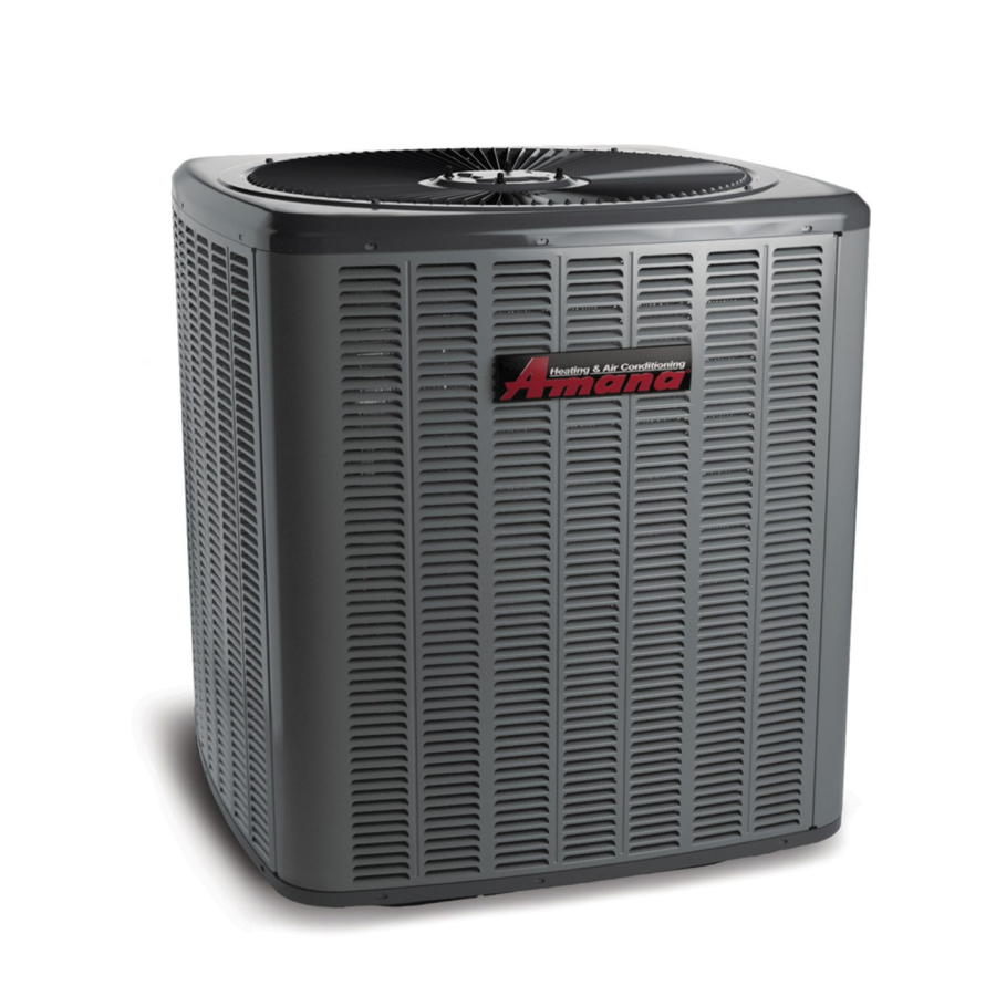
Amana ASXC16 Service And Troubleshooting

Amana ASXC16 Service And Troubleshooting

Asxc, dsxc, and gsxc condensing units, aszc, dszc, and gszc split system heat pumps with r-410a refrigerant blowers, coils, & accessories
Table of Contents

Advertisement

Service and Troubleshooting
with R-410A Refrigerant Blowers, Coils, & Accessories
Pride and workmanship go into every product to provide
our customers with quality products. It is possible, however,
that during its lifetime a product may require service.
Products should be serviced only by a qualified service
technician who is familiar with the safety procedures
required in the repair and who is equipped with the proper
tools, parts, testing instruments and the appropriate service
manual. REVIEW ALL SERVICE INFORMATION IN THE
APPROPRIATE SERVICE MANUAL BEFORE
BEGINNING REPAIRS.
Only personnel that have been trained to install, adjust,
service or repair (hereinafter, "service") the equipment
specified in this manual should service the equipment.
The manufacturer will not be responsible for any injury
or property damage arising from improper service or
service procedures. If you service this unit, you assume
responsibility for any injury or property damage which
may result. In addition, in jurisdictions that require one
or more licenses to service the equipment specified in
this manual, only licensed personnel should service the
equipment.
Improper installation, adjustment, servicing or repair of
the equipment specified in this manual, or attempting to
install, adjust, service or repair the equipment specified in
this manual without proper training may result in product
damage, property damage, personal injury or death.
Brand
is a registered trademark of Maytag Corporation or its related companies and is used under license. All rights reserved.
®
ASXC, DSXC, and GSXC Condensing units,
ASZC, DSZC, and GSZC Split System Heat Pumps
WARNING
©2020-2021 Goodman Manufacturing Company, L.P.
For service information related to the Bluetooth® Shared
Data Loader BTSDL01 referenced in this manual, please
refer to the installation instructions for the BTSDL01 at
www.coolcloudhvac.com/loaderuserguide.

TABLE OF CONTENTS

Important Information ............................................ 2
Product Information ............................................... 4
System Operation .................................................... 18
Servicing ..................................................................... 26
Checking Voltage ............................................... 26
Checking Wiring .................................................. 26
COMFORTBRIDGE™ TECHNOLOGY AIR
HANDLER (B*) ............................................................ 26
CHECKING TRANSFORMER AND
CONTROL CIRCUIT .................................................... 32
Checking Time Delay Relay .............................. 32
CHECKING UNITARY (UC) CONTROL
COMPRESSOR ........................................................... 32
CHECKING HIGH AND LOW VOLTAGE TO
ECM MOTOR .............................................................. 33
COPELAND COMFORT ALERT™ - UNITARY (UC)
CONTROL DIAGNOSTICS APPLIES TO ASXC, ASZC,
AND DSZC 2-STAGE MODELS ................................ 34
Checking Low Pressure Control ................ 34
CHECKING HIGH AND LOW PRESSURE SWITCH
VOLTAGE .................................................................... 35
Checking Capacitor ............................................ 35
RESISTANCE CHECK USING A DIGITAL
MULTI-METER ............................................................ 35
CAPACITANCE CHECK USING A DIGITAL
MULTI-METER (IN CAPACITANCE MODE) ............... 35
CHECKING EMERSON ULTRATECH™
ECM MOTORS ............................................................ 36
Checking Compressor ....................................... 39
Resistance Test .................................................. 39
Ground Test .......................................................... 40
RS6200007r25
April 2021

Advertisement

Table of Contents
loading

Summary of Contents for Amana ASXC16

  • Page 1 Service and Troubleshooting ASXC, DSXC, and GSXC Condensing units, ASZC, DSZC, and GSZC Split System Heat Pumps with R-410A Refrigerant Blowers, Coils, & Accessories Pride and workmanship go into every product to provide For service information related to the Bluetooth® Shared our customers with quality products.
  • Page 2 IMPORTANT INFORMATION IMPORTANT NOTICES FOR CONSUMERS UNLOADER TEST PROCEDURE WITH COMFORT ALERT™ UNITARY (UC) CONTROL DIAGNOSTICS 40 AND SERVICERS LOCKED ROTOR TEST ..........40 RECOGNIZE SAFETY SYMBOLS, WORDS AND OPERATION TEST ........... 41 LABELS TESTING CRANKCASE HEATER (OPTIONAL ITEM) 41 CHECKING REVERSING VALVE AND SOLENOID ...
  • Page 3 IMPORTANT INFORMATION Safe Refrigerant Handling WARNING While these items will not cover every conceivable situation, they should serve as a useful guide. The compressor POE oil for R-410A units is extremely susceptible to moisture absorption and could cause compressor failure. Do not leave system open to atmosphere any longer than necessary for installation.
  • Page 4 PRODUCT IDENTIFICATION...
  • Page 5 PRODUCT IDENTIFICATION...
  • Page 6 PRODUCT IDENTIFICATION Design Series Electrical MB Modular Blower 208- 230/60/1 Revisions Motor Speed First Series Variable Speed ECM Motor Circuit Breaker No Circuit Breaker Circuit Breaker 12 1200 CFM 16 1600 CFM 20 2000 CFM ComfortBridge...
  • Page 7 16 SEER 2-Stage AC Development with improved performance. ASXC18 AMANA® BRAND SPLIT X-COMMUNICATING CONDENSERS R-410A 18 SEER Model/Rev Description Initial release of Amana® brand 2-stage 16 SEER condensing units with R-410A, ASXC18**1AA communicating models. ASXC180(36/48/60)1AB Wiring diagram updated with notes.
  • Page 8 PRODUCT IDENTIFICATION GSXC16 GOODMAN® BRAND SPLIT X-COMMUNICATING CONDENSERS R-410A 16 SEER Model/Rev Description GSXC160(24/36/48/60)1CA 16 SEER 2-Stage AC Development with improved performance. GSXC18 GOODMAN® BRAND SPLIT X-COMMUNICATING CONDENSERS R-410A 18 SEER Model/Rev Description GSXC180(24/36/48/60)1BA 18 SEER 2-Stage AC Development with improved performance. [Design Improvement]: Updating shared data for 18 SEER, 2-stage, 4 ton AC in GSXC180481BB communicating installations.
  • Page 9 PRODUCT IDENTIFICATION DSXC16 DELUXE SPLIT X-COMMUNICATING CONDENSERS R-410A 16 SEER Model/Rev Description Initial release of Goodman® Deluxe brand 2-stage 16 SEER condensing units with R- DSXC160**1AA 410A, communicating models. DSXC160(24/36)1AB Wiring diagram updated with notes. DSXC160(24/36)1AC Ultratech® 2.0 compressor. DSXC160(48-60)1BC DSXC160481BA SmartCoil®...
  • Page 10 PRODUCT IDENTIFICATION ASZC16 AMANA® BRAND SPLIT Z-COMMUNICATING HEAT PUMP R-410A 16 SEER Model/Rev Description Introduces Amana® brand 2-stage 16 SEER heat pump units with R-410A, ASZC160**1AA communicating models. ASZC160(24/36)1AB Sanhua (RANCO) reversing valves ASZC160(48/60)1AB ASZC160(24-48)1AC Release of models with accumulators and crankcase heaters.
  • Page 11 PRODUCT IDENTIFICATION GSZC16 GOODMAN® BRAND SPLIT Z-COMMUNICATING HEAT PUMP R-410A 16 SEER Model/Rev Description Replaced compressors with Copeland's UltraTech™ 3 lineup. Transitioned coils to GSZC160[24/36/48/60]1CA 7mm. Offers improved performance. GSZC18 GOODMAN® BRAND SPLIT Z-COMMUNICATING HEAT PUMP R-410A 16 SEER Model/Rev Description Replaced compressors with Copeland's UltraTech™...
  • Page 12 PRODUCT IDENTIFICATION DSZC16 DELUXE SPLIT Z-COMMUNICATING HEAT PUMP R-410A 16 SEER Model/Rev Description Initial release of Goodman® brand Deluxe 2-stage 16 SEER heat pump units with R- DSZC16**1AA 410A, communicating models. DSZC160(24/36)1AB Sanhua (RANCO) reversing valves. DSZC160(48/60)1AB DSZC160(24-48)1AC Release of models with accumulators and crankcase heaters. DSZC160601BA DSZC160(24-48)]1AD DSZC160601BB...
  • Page 13 PRODUCT IDENTIFICATION AVPTC**14 SINGLE PIECE AIR HANDLER MULTIPLE-POSITION VARIABLE SPEED PAINTED TXV WITH 4-WIRE COMMUNICATING CONTROL Model/Rev Description AVPTC25B14BA AVPTC29B14BA AVPTC31C14BA AVPTC33C14BA AVPTC35B14BA AVPTC37B14BA AVPTC37C14BA ECM Based Air Handler with New Comfort Bridge™ Compatible PCB Control Board AVPTC37D14BA AVPTC39C14BA AVPTC49C14BA AVPTC49D14BA AVPTC59C14BA AVPTC59D14BA...
  • Page 14 PRODUCT IDENTIFICATION CAUF C-INDOOR COIL A-UPFLOW/DOWNFLOW UNCASED FLOWRATOR Model/Rev Description CAUF*****6AA Initial release of CAUF Dayton Upflow/Downflow coils. CAUF*****6BA Burr Oak Louvered Fin released in place of the Wavy Fin. CAUF****6*DA Replaced existing copper coils and other associated parts with aluminum components. CAUF*****6DB Drain pan material changed.
  • Page 15 PRODUCT IDENTIFICATION CHPF C-INDOOR COIL HORIZONTAL A-COIL PAINTED FLOWRATOR Model/Rev Description CHPF*****6AA Intial release of 13 SEER CHPF horizontal A coil. Released Burr Oak Louvered Fin in place of the Wavy Fin. The rows changed by one, (i.e. CHPF*****6BA 4 row to 3 row; 3 row to 2 row) where applicable. CHPF1824A6CA CHPF2430B6CA CHPF3636B6CA...
  • Page 16 PRODUCT IDENTIFICATION CAPF C-INDOOR COIL A-UPFLOW/DOWNFLOW PAINTED FLOWRATOR Model/Rev Description CAPF*****6AA Initial release of CAPF Dayton Upflow/Downflow coils. CAPF*****6BA Burr Oak Louvered Fin released in place of the Wavy Fin. CAPF36***CA Redesigned for performance improvement from 2 row to 3 row. CAPF*****6DA Replaced existing copper coils and other associated parts with aluminum components.
  • Page 17 PRODUCT IDENTIFICATION CAPT C-INDOOR OIL A-UPFLOW/DOWNFLOW PAINTED CASED FLOWRATOR W/TXV Model/Rev Description CAPT3131B4BA Initial release of coils with factory-installed, non-adjustable TXV. Single stage AHRI ratings CAPT3131C4BA for CAPT3131 NTC combinations. CAPT3743C4AA Initial release of single stage AHRI ratings for CAPT3743 NTC combinations. CAPT3743D4AA CAPT4961C4AA Initial release of single stage AHRI ratings for CAPT4961C4 NTC combinations.
  • Page 18 SYSTEM OPERATION Communicating System The communicating platform is a system that includes a Cooling Heating Models communicating air handler/furnace/modular blower and air High High conditioner or heat pump. Any other system configurations *SZC160241 are considered traditional (or legacy) system. *SZC160361 1200 1200 *SZC160481...
  • Page 19 SYSTEM OPERATION • Red Communications LED - Indicates the status of the Occasionally the need to trouble-shoot the network may network. The table below indicates the LED status and the arise. The integrated air handler control has some on- corresponding potential problem. board tools that may be used to troubleshoot the network.
  • Page 20 SYSTEM OPERATION Cooling It continues to soak up heat and vaporizes as it proceeds The refrigerant used in the system is R-410A. It is a clear, through the coil, cooling the indoor coil down to about 48°F. colorless, non-toxic and non-irritating liquid. R-410A is a 50:50 blend of R-32 and R-125.
  • Page 21 SYSTEM OPERATION Heating When the microprocessor detects the coil temperature to The heating portion of the refrigeration cycle is similar be high enough (approximately 75 0F), or 10 minutes of to the cooling cycle. By energizing the reversing valve maximum defrost cycle time has elapsed, whichever occurs solenoid coil, the flow of the refrigerant is reversed.
  • Page 22 EXPANSION VALVE/CHECK VALVE ASSEMBLY EXPANSION VALVE/CHECK VALVE ASSEMBLY IN COOLING OPERATION IN HEATING OPERATION Most expansion valves used in current Goodman/Amana Brand Heat Pump products ® use an internally checked expansion valve. This type of expansion valve does not require an external check valve as shown above.
  • Page 23 SYSTEM OPERATION SEQUENCE OF OPERATION 2.0 Heating Operation - Auxiliary/Emergency Heat 2.1 The thermostat sends a request for emergency heat to AVPTC/DSXC Condenser the air handler. The AVPTC air handler matched with an ASXC or GSXC condensing unit constitutes a communicating network. The 2.2 The air handler control energizes the ECM blower two components, or subsystems, making up the system motor at the emergency heat speed.
  • Page 24 SYSTEM OPERATION The CoolCloud HVAC app also allows the user to disable 1.10 Upon receiving a demand for auxiliary heat, the air the electric heaters in the air handler depending on the handler control determines the appropriate airflow for high outdoor temperature.
  • Page 25 SYSTEM OPERATION 3.2 The compressor may be de-energized for a short delay during the reversing valve shift. (The delay period is adjustable via the CoolCloud HVAC app or the push buttons on the indoor board. The compressor delay is intended to eliminate compressor noise during the reversing valve shift.) The compressor will energize (or re- energize) at high stage.
  • Page 26 SERVICING Checking Voltage Checking Wiring WARNING WARNING High Voltage! Disconnect all power before servicing High Voltage! or installing. Multiple power sources Disconnect all power before servicing or may be present. Failure to do so may installing. Multiple power sources may be present. Failure to do so may cause property damage, cause property damage, personal injury personal injury or death.
  • Page 27 SERVICING Cool Cloud HVAC Phone Application Quick Start Guide for Communicating Actual screens may look different based on the mobile Outdoor Units device being used. EXTREMELY IMPORTANT: For all cooling calls the system only requires a single Y input from the thermostat. For all heating calls (including applications with backup electric heater kits) the system only requires a single W input from the thermostat.
  • Page 28 SERVICING NOTE: When new versions of Bluetooth Communication Software and Air Handler Control Software are available, the phone application notifies the user. Software updates are classified as either optional or mandatory and installed by using the phone application. Ensure all mandatory software updates and install if necessary.
  • Page 29 SERVICING 3. Go to the Non-Comm Outdoor Setting Menu (0d5) using Auxiliary Alarm Switch the on board push buttons or the Cool Cloud HVAC The control is equipped with a 24VAC Aux Alarm to be phone application. Select “1AC” for single stage Air used for a condensate switch install (designated by Conditioners, “1HP”...
  • Page 30 SERVICING 4. Select the appropriate fan only airflow for the accessory using the indoor unit push button menus or the Cool Cloud HVAC phone application. 5. Using the thermostat, independently test each accessory in addition to the independently testing continuous fan mode.
  • Page 31 SERVICING Dehumidification Control Options Key Mitigations: Full featured TS (dehum & overcool) Connect G and dehum wire correctly Dehumidistat Dehumidification Control Options Dry Environment Install any 24VAC Thermostat has a Dehum or thermostat on the Configurable terminal with market - Use Y, W, G Dehum option signals Install Dehumidistat in...
  • Page 32 SERVICING Checking Transformer and Control Circuit Checking Time Delay Relay Time delays are used in electric heaters to sequence in multiple electric heaters. WARNING WARNING High Voltage! Disconnect all power before servicing or installing. Multiple power sources Disconnect ALL power before servicing may be present.
  • Page 33 SERVICING Contactor/Relay Contacts WARNING Disconnect ALL power before servicing 1. Connect voltmeter to lugs (L2) and (C). 2. With power ON, provide a call for cool or heat pump to energize the on-board compressor contactor/relay. WARNING Line voltage now present 3.
  • Page 34 SERVICING Copeland Comfort Alert™ - Unitary (UC) Control Test 2. Testing High Pressure Control in Heating Diagnostics Applies to ASXC, ASZC, And DSZC Mode 1. Connect refrigerant gages to unit. 2-Stage Models 2. Disconnect power to indoor unit. 3. Remove control panel cover. WARNING 4.
  • Page 35 SERVICING Test 2. Testing Low Pressure Control in Heating Mode WARNING 1. Connect refrigerant gages to unit. 2. Disconnect power to outdoor unit. Discharge capacitor through a 200 to 300 OHM 3. Remove control panel cover. resistor before handling. 4. Disconnect black wire from condenser fan motor (single 2.
  • Page 36 Repair or replace as needed. characteristics and reduce light dimming within the 4. Check thermostat and thermostat wiring. Ensure home. Only hard start kits approved by Amana® brand thermostat is providing proper cooling/heating/ or Copeland should be used. “Kick Start” and/or “Super continuous fan demands.
  • Page 37 SERVICING NOTE: The UltraCheck-EZ™ diagnostic tool is Electrical Checks - High Voltage Power Circuits equipped with a non-replaceable fuse. Connecting the tool to a source other than 24VAC could damage the WARNING tool and cause the fuse to open. Doing so will render the diagnostic tool inoperable.
  • Page 38 SERVICING 6. Inspect the large capacitors inside the control/end bell Electrical Checks - Low Voltage Control Circuits 1. Turn on power to air handler or modular. (see figure below). Replace the control/end bell if any of the capacitors are bulging or swollen. WARNING Line voltage now present 2.
  • Page 39 SERVICING Heat generated within the compressor shell, usually due to Checking Compressor recycling of the motor, high amperage or insufficient gas to cool the motor, is slow to dissipate. Allow at least three to WARNING four hours for it to cool and reset, then retest. Fuse, circuit breaker, ground fault protective device, etc.
  • Page 40 SERVICING If you suspected that the unloader is not working, the Ground Test following methods may be used to verify operation. If fuse, circuit breaker, ground fault protective device, etc. has tripped, this is a strong indication that an electrical problem exists and must be found and corrected.
  • Page 41 SERVICING With power ON: WARNING WARNING Line voltage now present Line voltage now present A. If the compressor starts and continues to run, 1. Check the serial data plate for the compressor locked the cause for failure is somewhere else in the rotor amps (LRA) rating.
  • Page 42 SERVICING Testing Defrost Control Checking Reversing Valve and Solenoid Occasionally the reversing valve may stick in the heating or Legacy Models: cooling position or in the mid-position. Communicating Units: To check the defrost control for proper sequencing, When stuck in the mid-position, part of the discharge gas proceed as follows: With power ON;...
  • Page 43 SERVICING To check either the outdoor air or outdoor coil temperature Troubleshooting sensors: Motor Control Circuits WARNING WARNING High Voltage! Disconnect all power before servicing or installing. Multiple power sources High Voltage! may be present. Failure to do so may Disconnect all power before servicing cause property damage, personal injury or installing.
  • Page 44 SERVICING 4. Provide a thermostat demand for high stage auxiliary • Typical 18 AWG thermostat wire may be used to wire heat (W1 + W2). Measure the voltage between the system components. One hundred feet is the circuits 1 and 3 at the on-board electric heat connector. maximum length of wire between indoor and outdoor Measure the voltage between circuits 2 and 3 at the on- units or between indoor unit and thermostat.
  • Page 45 SERVICING Answer: 24.0KW, 42°F Rise, 240 V = 1800 CFM from the Control System – General Information TEMPERATURE RISE chart on the right. The air handler contains internal logic to control equipment Heating output at 220 V = 24.0KW x 3.413 x .84 = 68.8 staging.
  • Page 46 SERVICING 1. Stage Up Percent (7 segment menu SUP): This is a The system will automatically make adjustments in an value that determines how far past the target runtime attempt to satisfy the thermostat as close to this target the system should continue running the heat pump runtime as possible.
  • Page 47 SERVICING Max CFM is as follows: Checking Heater Fuse Link 3 Ton Models 1400 CFM (Optional Electric Heaters) 4 Ton Models 1760 CFM Each individual heater element is protected with a one time 5 Ton Models 2200 CFM fuse link which is connected in series with the element. The fuse link will open at approximately 333°.
  • Page 48 SERVICING 1. Never open a system that is under vacuum. Air and Leak test the system using dry nitrogen and soapy moisture will be drawn in. water to identify leaks. If you prefer to use an electronic 2. Plug or cap all openings. leak detector, charge the system to 10 PSIG with the 3.
  • Page 49 SERVICING 2. Evacuate to 1500 microns and hold for 20 minutes. considered leak-free; proceed to system charging and Break the vacuum with dry nitrogen again, bring the startup. system pressure back to 2-3 PSIG, and hold for 20 4. If pressure rises above 1000 microns but holds steady minutes.
  • Page 50 SERVICING condensing unit. If using evaporator coils or air handlers NOTE: Superheat adjustments should not be made other than HSVTC coil it may be necessary to add or until indoor ambient conditions have stabilized. This could take up to 24 hours depending on indoor remove refrigerant to attain proper charge.
  • Page 51 SERVICING 4. Disconnect manifold set, installation is complete. Superheat The expansion valves are factory adjusted to maintain 7 to SUBCOOLING FORMULA = SATURATED LIQUID TEMP. 9 degrees superheat of the suction gas. Before checking - LIQUID LINE TEMP. the superheat or replacing the valve, perform all the procedures outlined under Air Flow, Refrigerant Charge, NOTE: Check the Schrader ports for leaks and tighten Expansion Valve - Overfeeding, Underfeeding.
  • Page 52 SERVICING 4. If a temperature or pressure change is noticed, the Checking Subcooling expansion valve is operating. If no change is noticed, Refrigerant liquid is considered subcooled when its the valve is restricted, the power element is faulty, or temperature is lower than the saturation temperature the equalizer tube is plugged.
  • Page 53 SERVICING EXPANSION VALVE KITS For Applications requiring 1/4 FLARE CONNECTION a field installed access fitting BULB TO BE LOCATED AT 10 OR 2 O'CLOCK BULB SUCTION LINE EVAPORATOR COIL TAILPIECE PISTON SEAL SUPPLIED W/ KIT SEAL SUPPLIED W/ KIT SEAL DISTRIBUTOR EXPANSION VALVE BODY...
  • Page 54 SERVICING Pressure vs. Temperature Chart R-410A PSIG °F PSIG °F PSIG °F PSIG °F PSIG °F PSIG °F -37.7 114.0 37.8 216.0 74.3 318.0 100.2 420.0 120.7 522.0 137.6 -34.7 116.0 38.7 218.0 74.9 320.0 100.7 422.0 121.0 524.0 137.9 -32.0 118.0 39.5...
  • Page 55 SERVICING REQUIRED LIQUID LINE TEMPERATURE LIQUID PRESSURE REQUIRED SUBCOOLING TEMPERATURE (°F) AT SERVICE VALVE (PSIG)
  • Page 56 If the pressure indicates a higher temperature than that of the coil temperature, non-condensables are present. NOTE: The Flushing Method using R-11 refrigerant is no longer approved by Amana® Brand Heating- Non-condensables are removed from the system by first Cooling.
  • Page 57 SERVICING Suction Line Drier Clean-Up Method POE oils maintain a consistent viscosity over a large The POE oils used with R410A refrigerant is an excellent temperature range which aids in the oil return to the solvent. In the case of a burnout, the POE oils will remove compressor;...
  • Page 58 SERVICING Maintenance Motors Indoor and Outdoor motors are permanently lubricated and do not need additional oiling. Cleaning Outdoor Coil 1. Check for oil deposits on coil this could be an indication of possible leak. If no leak detected spray coil with ordinary household detergent.
  • Page 59 SERVICING Air Handler Troubleshooting Matrix (B*) Diagnostic / Symptoms of Abnormal Status LED Fault Description Possible Causes Corrective Actions Operation Codes Improper low voltage wiring Locate and correct improper low between the indoor and voltage wiring issue Communication error outdoor unit No outdoor unit operations with outdoor unit Identify reason outdoor control...
  • Page 60 SERVICING Air Handler Troubleshooting Matrix (B*) Diagnostic / Symptoms of Abnormal Operation Status LED Fault Description Possible Causes Corrective Actions Codes Circulator blower motor Abnormal motor loading, sudden senses a loss of rotor control Check filters, filter grills/registers, duct change in speed or torque, sudden No Air Handler operation system and air handler inlet/outlet for blockage of air handler air inlet or...
  • Page 61 SERVICING Air Handler Display (B*) LED Display Menu Description View 6 most recent fault codes and Clear Fault Codes if desired (furnace) Lr n Restart communications between the indoor and outdoor unit. Control Firmware Revision Number Control Shared Data Revision Number Constant Fan Speed as percent of maximum airflow.
  • Page 62 SERVICING Air Handler Display (B*) LED Display Menu Description View 6 most recent fault codes and Clear Fault Codes if desired (outdoor communicating units) Menu is enabled if the CFS menu is set to 6. Select the target time t gt the system will attempt to satisfy the thermostat.
  • Page 63 SERVICING Air Handler Display (B*) LED Display Description of System Status Idle Constant Fan Compressor Cooling, Single-Stage (non-comm units) Compressor Cooling, Low Stage (non-comm units) Compressor Cooling, High Stage (non-comm units) Compressor Cooling, Low Stage (comm units) Compressor Cooling, High Stage (comm units) Compressor Heat, Single Stage (non-comm units) Compressor Heat, Low Stage (non-comm units) Compressor Heat, High Stage (non-comm units)
  • Page 64 SERVICING Air Handler Label (B*) Menu Navigation and Selection Instructions Tonnage Menu (t o n) Using Phone Application over Bluetooth Network: 1) Connect to the air handler (instructions provided by phone during Tonnage Tonnage connection process). Airflow Airflow 2) Select desired settings menu Selection Selection 3) Select item that requires adjustment and make necessary selection...
  • Page 65 SERVICING PCBHR101-103 PBBGR101-102...
  • Page 66 SERVICING PCBHR101-103 PBBGR101-102...
  • Page 67 SERVICING PCBHR101-103 PBBGR101-102...
  • Page 68 SERVICING PCBHR101-103 PBBGR101-102...
  • Page 69 SERVICING PCBHR101-103 PBBGR101-102...
  • Page 70 SERVICING PCBHR104/PCBHR105...
  • Page 71 SERVICING PCBHR104 System Troubleshooting UNITARY DIAGNOSTIC CODES Diagnostic/Status LED Symptoms Fault Corrective Display Codes of Abnormal Possible Causes Notes & Cautions Digit 3 Digit Digit 1 Description Actions Operation • Integrated control BLANK • Outdoor air • Shorted sensor. • Check sensor •...
  • Page 72 SERVICING PCBHR104 UNITARY DIAGNOSTIC CODES Symptoms Diagnostic/Status LED Display Fault Corrective Codes of Abnormal Possible Causes Notes & Cautions Description Actions Digit 3 Digit 2 Digit 1 Operation • Air conditioner/heat BLANK • Data not yet • Air conditioner/ • Verify system type •...
  • Page 73 SERVICING PCBHR104 UNITARY DIAGNOSTIC CODES Symptoms Diagnostic/Status LED Fault Possible Corrective Display Codes of Abnormal Notes & Cautions Description Causes Actions Digit 3 Digit 2 Digit 1 Operation • Air conditioner/heat BLANK • Configuration • Shared data • Verify • Turn power OFF prior to pump fails to operate Mismatch sent to integrated...
  • Page 74 SERVICING PCBHR104 UNITARY DIAGNOSTIC CODES Symptoms Diagnostic/Status LED Fault Possible Corrective of Abnormal Display Codes Notes & Cautions Description Causes Actions Digit 3 Digit 2 Digit 1 Operation • Compressor and BLANK • Low Pressure • Low refrigerant • Verify refrigerant •...
  • Page 75 SERVICING PCBHR104 UNITARY DIAGNOSTIC CODES Symptoms Diagnostic/Status LED Fault Possible Corrective Notes & of Abnormal Display Codes Description Causes Actions Cautions Digit 3 Digit 2 Digit 1 Operation • Run time for last 4 BLANK • Short Cycling • Intermittent •...
  • Page 76 SERVICING PCBHR104 UNITARY DIAGNOSTIC CODES Symptoms Diagnostic/Status LED Fault Possible Corrective Notes & of Abnormal Display Codes Description Causes Actions Cautions Digit 3 Digit 2 Digit 1 Operation • Compressor and BLANK • Open Start • Compressor • Check • Turn power OFF outdoor fan are off Circuit Lockout start winding is...
  • Page 77 SERVICING PCBHR104 UNITARY DIAGNOSTIC CODES Symptoms Diagnostic/Status LED Fault Possible Corrective Notes & of Abnormal Display Codes Description Causes Actions Cautions Digit 3 Digit 2 Digit 1 Operation • Air conditioner/heat BLANK • High Line • High line voltage • Correct high •...
  • Page 78 SERVICING PCBHR105 UNITARY DIAGNOSTIC CODES Symptoms Diagnostic/Status LED Fault Possible Corrective Notes & of Abnormal Display Codes Description Causes Actions Cautions Digit 3 Digit 2 Digit 1 Operation • Integrated control BLANK • Outdoor air • Shorted sensor • Check sensor •...
  • Page 79 SERVICING PCBHR105 UNITARY DIAGNOSTIC CODES Symptoms Diagnostic/Status LED Fault Possible Corrective Notes & of Abnormal Display Codes Description Causes Actions Cautions Digit 3 Digit 2 Digit 1 Operation • Air conditioner/heat BLANK • Data not yet on • Air conditioner/ •...
  • Page 80 SERVICING PCBHR105 UNITARY DIAGNOSTIC CODES Diagnostic/Status LED Symptoms Fault Corrective Display Codes of Abnormal Possible Causes Notes & Cautions Description Actions Digit 3 Digit 2 Digit 1 Operation • Air conditioner/heat BLANK • Configuration • Shared data sent • Verify •...
  • Page 81 SERVICING PCBHR105 UNITARY DIAGNOSTIC CODES Symptoms Diagnostic/Status LED Fault Possible Corrective Notes & of Abnormal Display Codes Description Causes Actions Cautions Digit 3 Digit 2 Digit 1 Operation • Compressor and BLANK • Low Pressure • Low refrigerant • Verify refrigerant •...
  • Page 82 SERVICING PCBHR105 UNITARY DIAGNOSTIC CODES Symptoms Diagnostic/Status LED Fault Possible Corrective Notes & of Abnormal Display Codes Description Causes Actions Cautions Digit 3 Digit 2 Digit 1 Operation • Run time for last 4 BLANK • Short Cycling • Intermittent •...
  • Page 83 SERVICING PCBHR105 UNITARY DIAGNOSTIC CODES Diagnostic/Status Symptoms Fault Possible Corrective LED Display Codes of Abnormal Notes & Cautions Digit 3 Digit Digit Description Causes Actions Operation • Compressor and BLANK • Open Start • Compressor • Check • Turn power OFF outdoor fan are off Circuit Lockout start winding is...
  • Page 84 SERVICING PCBHR105 UNITARY DIAGNOSTIC CODES Diagnostic/Status Symptoms Fault Possible Corrective LED Display Codes of Abnormal Notes & Cautions Digit 3 Digit Digit Description Causes Actions Operation • Air conditioner/heat BLANK • High Line • High line voltage • Correct high •...
  • Page 85 WIRING DIAGRAMS 3-Phase Heat Kit 25kW Heat Kit Wiring is subject to change. Always refer to the wiring diagram on the unit for the most up-to-date wiring.
  • Page 86 WIRING DIAGRAMS A/GSXC16 & A/GSZC16 OAT OCT Wiring is subject to change. Always refer to the wiring diagram on the unit for the most up-to-date wiring.
  • Page 87 WIRING DIAGRAMS A/GSXC18 & A/GSZC18 A/GSXC16060 & A/GSZC16060 Wiring is subject to change. Always refer to the wiring diagram on the unit for the most up-to-date wiring.
  • Page 88 WIRING DIAGRAMS A/DSZC18 Wiring is subject to change. Always refer to the wiring diagram on the unit for the most up-to-date wiring.
  • Page 89 WIRING DIAGRAMS AVPTC(B*) (SEE NOTE 4) 208/230 VAC GROUND LUG L2 L1 HEATER KIT (SEE NOTE 6) RD BK GRND ECM MOTOR DISCONNECT MOTOR 24VAC 24VAC (SEE NOTE 1) (SEE NOTE 1) INDOOR CIRCULATOR GY BL BLWR GRND 208/230 VAC INSTALLING AUX ALARM (ALARM)
  • Page 90 WIRING DIAGRAMS AVPTC(BB*) (SEE NOTE 4) 208/230 VAC GROUND LUG L2 L1 HEATER KIT (SEE NOTE 6) RD BK GRND ECM MOTOR DISCONNECT MOTOR 24VAC (SEE NOTE 1) INDOOR CIRCULATOR BK RD BLWR GRND 208/230 VAC INSTALLING AUX ALARM (ALARM) (SEE NOTE 7) AUX ALARM AUX ALARM...
  • Page 91 WIRING DIAGRAMS MBVC 1201 40 VA TRANSFORMER, SEE NOTE 1 230 VAC GRND GRND 208 VAC 24 VAC DISCONNECT INDOOR CIRCULATOR BLWR NOTE 7 GRND 208/230 VAC 40 VA FUSE 3 A TRANSFORMER 24 VAC ELECTRIC HEAT STAGE 1 ELECTRIC STAGE 2 AUX IN CONDENSATE SWITCH AUX OUT...
  • Page 92 Please fill out the feedback form on one of the following links: Goodman Brand Products: (http://www.goodmanmfg.com/about/contact-us). ® Amana Brand Products: (http://www.amana-hac.com/about-us/contact-us). ® You can also scan the QR code on the right for the product brand you purchased to be directed to the feedback page. GOODMAN BRAND ®...

Table of Contents