Table of Contents
Advertisement
Quick Links
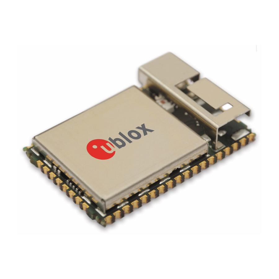
ODIN-W2 series
Stand-alone multiradio modules with
Wi-Fi & Bluetooth
Data Sheet
Abstract
This technical data sheet describes the ODIN-W2 series short range
multiradio modules with Wi-Fi and Bluetooth dual mode 4.0
(Classic Bluetooth and Bluetooth Low Energy). The ODIN-W2 is a
compact yet powerful stand-alone multiradio module designed for
Internet-of-Things applications in the compact ODIN form factor.
The Wi-Fi support conforms to IEEE 802.11a/b/g/n, and has support
for dual-band 2.4 GHz and 5 GHz operation and 2×2 MIMO (2.4
GHz).
www.u-blox.com
UBX-14039949 - R05
Advertisement
Table of Contents

Related Manuals for u-blox ODIN-W2 Series


Summary of Contents for u-blox ODIN-W2 Series
- Page 1 Wi-Fi & Bluetooth Data Sheet Abstract This technical data sheet describes the ODIN-W2 series short range multiradio modules with Wi-Fi and Bluetooth dual mode 4.0 (Classic Bluetooth and Bluetooth Low Energy). The ODIN-W2 is a compact yet powerful stand-alone multiradio module designed for Internet-of-Things applications in the compact ODIN form factor.
- Page 2 This document may be revised by u-blox at any time. For most recent documents, visit www.u-blox.com. Copyright © 2015, u-blox AG. u-blox® is a registered trademark of u-blox Holding AG in the EU and other countries. ARM® is the registered trademark of ARM Limited in the EU and other countries.
-
Page 3: Table Of Contents
ODIN-W2 series - Data Sheet Contents Contents ..........................3 Functional description ....................6 Overview .............................. 6 Applications ............................6 Product features ........................... 6 Block diagram ............................7 Product description ..........................7 AT command support ........................... 8 IEEE 802.11d and additional regulatory domains .................. 8 1.7.1... - Page 4 ODIN-W2 series - Data Sheet 5.3.2 Wi-Fi 2.4 GHz power consumption ....................19 5.3.3 Wi-Fi 5 GHz power consumption ....................19 5.3.4 Classic Bluetooth power consumption ..................20 5.3.5 Bluetooth Low Energy (BLE) power consumption ................. 20 RF characteristics ..........................20 5.4.1...
- Page 5 ODIN-W2 series - Data Sheet A Glossary ........................34 Related documents......................35 Revision history ........................ 35 Contact ..........................36 UBX-14039949 - R05 Advance Information Contents Page 5 of 36...
-
Page 6: Functional Description
1 Functional description Overview The ODIN-W2 series is a highly integrated multiradio module developed by u-blox for integration in demanding, reliable devices such as those needed for industrial and medical applications. The module is built around a multiradio chip, which includes Wi-Fi, Classic Bluetooth and Bluetooth Low Energy (Dual Mode / Bluetooth Smart Ready). -
Page 7: Block Diagram
Figure 1: Block diagram of ODIN-W2 series Product description The ODIN-W2 series module supports Wi-Fi, classic Bluetooth and Bluetooth Low Energy (dual mode / Bluetooth Smart Ready). The Wi-Fi support conforms to IEEE 802.11a/b/g/n, and has support for dual-band 2.4 GHz and 5 GHz operation and 2×2 MIMO (2.4 GHz). -
Page 8: At Command Support
ODIN-W2 series - Data Sheet AT command support The ODIN-W2 series modules support AT commands as described in the ODIN-W2 AT Commands Manual [1]. See also the s-center software, which is an easy-to-use tool from u-blox for evaluating, and configuration of u-blox Short Range modules. - Page 9 ODIN-W2 series - Data Sheet If the scan result contains country information indicating both FCC and country information indicating ETSI, then the regulatory domain is set to WORLD. In the state transition diagram this is the state WORLD_FINAL. This state will not be exited until the device is reset.
-
Page 10: Interfaces
2.1.1 Module supply input (VCC) The ODIN-W2 series modules must be supplied through the VCC pin by a DC power supply. Voltage must be stable, because during operation the current drawn from VCC can vary significantly based on the power consumption profile of the Bluetooth/Wi-Fi technologies. -
Page 11: Data Communication Interfaces
The ODIN-W2 series provides several data communication interfaces which are described below. 2.3.1 UART interface The ODIN-W2 series modules include a 6-wire UART for communication with an application host processor (AT commands, Data communication and firmware upgrades). The following UART signals are available: •... - Page 12 ODIN-W2 series - Data Sheet The IO voltage of the ODIN-W2 is 1.8 V, which means that the RMII interface operates outside the RMII specification v1.2. If the RMII is to be connected to a PHY circuit, then that circuit must support 1.8 V operation.
-
Page 13: System Functions
Support for power save mode is available in version ODIN-W26x-01B-00. The ODIN-W2 series module does not have an internal low power oscillator (LPO) which is required for low power modes. An external 32.768 kHz LPO signal can be supplied externally via the LPO_CLK pin if low power modes are required. -
Page 14: Pin Definition
4 Pin definition Pin assignment Figure 4: ODIN-W2 series pin assignment The signals are available on castellation pads on the edge of the PCB. All non-filled round pads are GND pads. Black circular pads are test and production points that should not be used. RSVD = Reserved, do not connect. - Page 15 ODIN-W2 series - Data Sheet Name Description Remarks RESET_N External reset input. Internal active pull-up to V_INT. V_INT Regulated output of the 1.8V, maximum output current 100mA. The maximum output internal I/O voltage. current can be limited by the internal current consumption of the V_INT rail.
- Page 16 ODIN-W2 series - Data Sheet Name Description Remarks RSVD Reserved pin. Leave unconnected. RSVD Reserved pin. Leave unconnected. RSVD Reserved pin. Leave unconnected. RSVD Reserved pin. Leave unconnected. Ground All GND pads must be connected to ground. RSVD Reserved pin.
-
Page 17: Electrical Specification
ODIN-W2 series - Data Sheet 5 Electrical specification Stressing the device above one or more of the ratings listed in the Absolute maximum ratings section may cause permanent damage. These are stress ratings only. Operating the module at these or at any conditions other than those specified in the Operating conditions section should be avoided. -
Page 18: I/O Dc Characteristics
Table 10: Reset characteristics 5.2.5 LPO clock The ODIN-W2 series module does not have an internal low power oscillator (LPO) required for low power modes. An LPO can be supplied from an external oscillator if low power modes are required. -
Page 19: Power Consumption
ODIN-W2 series - Data Sheet Power consumption These measurements were made while running preliminary firmware (see the product version information on page 2) and are subject to change. No power save functionality is supported yet and especially the idle current consumption will be significantly reduced in coming firmwares. -
Page 20: Classic Bluetooth Power Consumption
ODIN-W2 series - Data Sheet Average during transmission. UART 3 Mbit/s Average value for one transmission period. Measured maximum at maximum output power. **** Feature not supported in the current firmware version. See [1] for more information Table 15: Current consumption for Wi-Fi 5 GHz 5.3.4 Classic Bluetooth power consumption... -
Page 21: Wi-Fi Receiver Characteristics 5 Ghz
ODIN-W2 series - Data Sheet Channel / IEEE Parameter Test conditions Antenna port Unit Freq [MHz] limit PER ≤ 10% 2x2 MIMO MIMO port (stream 2) 6 / 2437 802.11n , Rate = 130 Mbit/s (MCS15), MAIN port (stream 1) 6 / 2437 PER ≤... -
Page 22: Bluetooth Classic Receiver Characteristics
ODIN-W2 series - Data Sheet Channel / IEEE EVM Parameter Test conditions Unit Freq [MHz] limit 100 / 5500 140 / 5700 802.11n , Rate = 65 Mbit/s (MCS7) 40 / 5180 100 / 5500 140 / 5700 Measured conducted on ODIN-W260 with maximum output power, measurement tolerance ±1.0 dB. -
Page 23: Mechanical Specifications
ODIN-W2 series - Data Sheet 6 Mechanical specifications Dimensions Figure 5: Physical dimensions of ODIN-W260 UBX-14039949 - R05 Advance Information Mechanical specifications Page 23 of 36... -
Page 24: Module Weight
ODIN-W2 series - Data Sheet Figure 6: Physical dimensions of ODIN-W262 Module weight Module Unit ODIN-W260 ODIN-W262 Table 26: Module weight UBX-14039949 - R05 Advance Information Mechanical specifications Page 24 of 36... -
Page 25: Qualification And Approvals
ODIN-W2 series - Data Sheet 7 Qualification and approvals The ODIN-W2 series modules are in Advance Information status as mentioned in Document status section. Hence, the following information is not fully valid and completed yet but will be valid when the module is fully tested and approved in the Production Information stage as mentioned in the Document status section on page 2: •... -
Page 26: Safety Compliance
In order to fulfill the safety standard EN 60950-1 the unit must be supplied by a limited power source. FCC and IC Compliance The ODIN-W2 series modules are in Advance Information status as mentioned in Document status section. Hence, the information in this section is not fully valid and completed yet but will be when the module is fully tested and approved in the Production Information stage as mentioned in the Document status section on page 2. -
Page 27: Fcc Statement
Any changes or modifications NOT explicitly APPROVED by u-blox could cause the module to cease to comply with FCC rules part 15, and thus void the user's authority to operate the equipment. -
Page 28: Japan Radio Equipment Compliance
The very small size of the module makes it not reasonable to fit the GITEKI mark and certification number onto the module label. Instead the Giteki mark and certification number is available in the ODIN-W2 series System Integration Manual [2] and on the ODIN-W2 package. -
Page 29: Bluetooth Qualification Information
Document status section on page 2. The ODIN-W2 series modules have been qualified according to the Bluetooth 4.0 specification. For information how to list and declare your product see the ODIN-W2 series System Integration Manual [2][2]. UBX-14039949 - R05... -
Page 30: Product Handling And Soldering
ODIN-W2 series - Data Sheet 8 Product handling and soldering Packaging The ODIN-W2 series modules are delivered as hermetically sealed, reeled tapes to enable efficient production, production lot set-up and tear-down. For more information about packaging, see the u-blox Package Information Guide [3]. -
Page 31: Moisture Sensitivity Levels
Proper ESD handling and packaging procedures must be applied throughout the processing, handling and operation of any application that incorporates the ODIN-W2 series module. The ESD precautions should be implemented on the application board where the module is mounted as described in the ODIN-W2 series System Integration Manual [2]. -
Page 32: Labeling And Ordering Information
The labels of the ODIN-W2 series modules include important product information as described in this section. Figure 8 illustrates the label of all the ODIN-W2 series modules, which includes u-blox logo, production lot, product type number and certification numbers (if applicable). -
Page 33: Explanation Of Codes
Three different product code formats are used. The Product Name is used in documentation such as this data sheet and identifies all u-blox products, independent of packaging and quality grade. The Ordering Code includes options and quality, while the Type Number includes the hardware and firmware versions. Table 29... -
Page 34: Appendix
ODIN-W2 series - Data Sheet Appendix A Glossary Name Definition Analog to Digital Converter Bluetooth Controller Area Network Clear To Send Direct Current Data Set Ready Data Terminal Ready EIRP Equivalent Isotropically Radiated Power Firmware Ground GPIO General Purpose Input Output... -
Page 35: Related Documents
ODIN-W2 AT Commands Manual, document number UBX-14044127 ODIN-W2 series System Integration Manual, document number UBX-14040040 u-blox Package Information Guide, document number UBX-14001652 For regular updates to u-blox documentation and to receive product change notifications please register on our homepage. Revision history... -
Page 36: Contact
ODIN-W2 series - Data Sheet Contact For complete contact information visit us at www.u-blox.com. u-blox Offices North, Central and South America Headquarters Asia, Australia, Pacific Europe, Middle East, Africa u-blox America, Inc. u-blox Singapore Pte. Ltd. u-blox AG Phone: +1 703 483 3180...
Need help?
Do you have a question about the ODIN-W2 Series and is the answer not in the manual?
Questions and answers