
Related Manuals for Clarke WH215


Summary of Contents for Clarke WH215
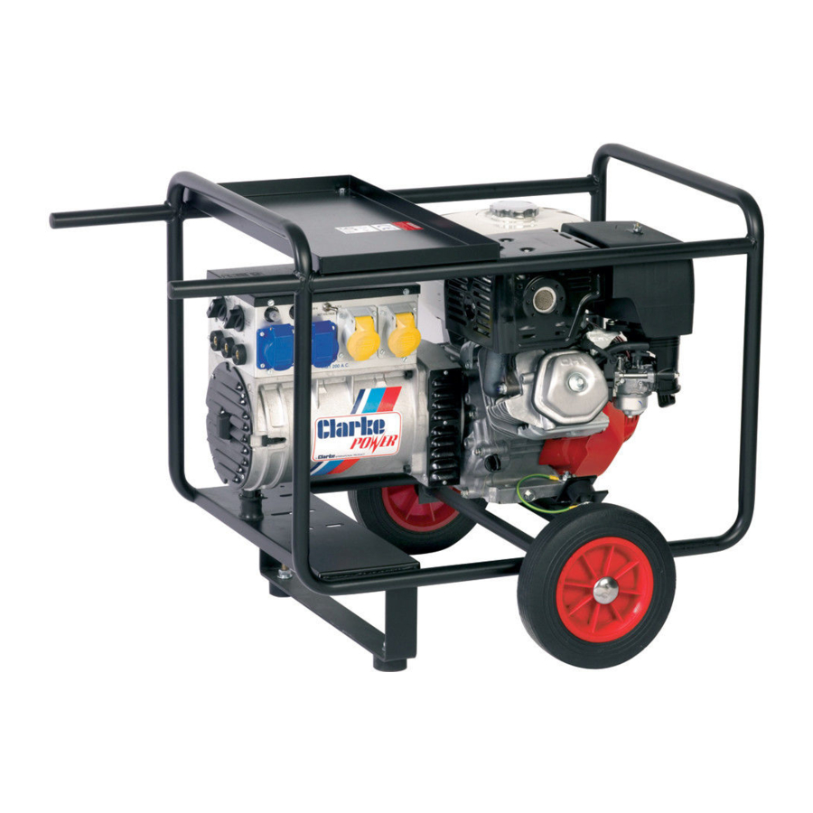
- Page 1 WELDER GENERATOR MODEL NO: WH215 PART NO: 8130535 OPERATION & MAINTENANCE INSTRUCTIONS ORIGINAL INSTRUCTIONS GC0320...
-
Page 2: Environmental Recycling Policy
Please note that the details and specifications contained herein, are correct at the time of going to print. However, CLARKE International reserve the right to change specifications at any time without prior notice. ALWAYS CONSULT THE MACHINE’S DATA PLATE. -
Page 3: General Precautions
GENERAL SAFETY PRECAUTIONS FOR ALL TYPES OF WELDING WARNING: AS WITH ALL MACHINERY, THERE ARE CERTAIN HAZARDS INVOLVED WITH THEIR OPERATION AND USE. EXERCISING RESPECT AND CAUTION WILL CONSIDERABLY LESSEN THE RISK OF PERSONAL INJURY. HOWEVER, IF NORMAL SAFETY PRECAUTIONS ARE OVERLOOKED, OR IGNORED, PERSONAL INJURY TO THE OPERATOR MAY RESULT. - Page 4 energy of the arc can also decompose trichloroethylene and perchloroethylene vapours to form phosgene. DO NOT WELD or cut where solvent vapours can be drawn into the welding or cutting atmosphere or where the radiant energy can penetrate to atmospheres containing even minute amounts of trichloroethylene or perchloroethylene.
- Page 5 A container with unknown contents should be cleaned (see paragraph above). Do NOT depend on sense of smell or sight to determine if it is safe to weld or cut. Hollow castings or containers must be vented before welding or cutting - they can explode.
- Page 6 leave a permanent dark area in the field of vision. Before welding whilst wearing contact lenses, seek advice from your optician. PROTECTION OF NEARBY PERSONNEL For production welding, a separate, well vented room or enclosed bay is best. In open areas, surround the operation with low reflection, non- combustible screens or panels.
- Page 7 Examples of conducting objects include, but are not limited to, buildings, electrical tools, work benches, welding power source cases, workpieces, etc. Never touch the electrode and any metal object unless the welding power source is off. When installing, connect the frames of each unit such as the welding power source, control, work table and water circulator to the building earth.
-
Page 8: Electromagnetic Interference (Emc)
7) SAFETY DEVICES Safety devices such as interlocks and circuit breakers should not be disconnected or shunted out. Before installation, inspection, or service of equipment, shut OFF all power and remove line fuses (or lock or red-tag switches) to prevent accidental turning ON of power. Do not open power circuit or change polarity while welding. -
Page 9: Welding Cables
• other equipment in the environment. The user shall ensure that other equipment being used in the environment is compatible. This may require additional protection measures; It may be possible to avoid the above by changing the time of day that welding or other activities are to be carried out. -
Page 10: Screening And Shielding
Care should be taken to prevent the earthing of the workpiece increasing the risk of injury to users, or damage to other electrical equipment. Where necessary, the connection of the workpiece to earth should be made by a direct connection to the workpiece, but in some countries where direct connection is not permitted, the bonding should be achieved by suitable capacitance, selected according to national regulations. -
Page 11: Preparation Of The Working Area
PREPARATION OF THE WORKING AREA The working area must be sufficiently spacious, with low humidity and well- ventilated so as to avoid any fumes which develop from the welding process and from incidental material adhering to the pieces to be welded (oils, paints, tars...) which may cause danger to the operator. -
Page 12: Exhaust Gas Precautions
• NEVER attempt any electrical or mechanical repair unless your are a qualified technician. If you have a problem with the machine contact your local CLARKE dealer. • NEVER use or store in a wet/damp environment. DO NOT EXPOSE TO RAIN. -
Page 13: Preparation For Use
PREPARATION FOR USE FUELLING Fill with fuel, according to the instructions within the engine manual. NOTE: Always use a fuel funnel to fill the tank so as to avoid accidental spillage of fuel. If fuel is spilled it must be removed from the unit and the surrounding area, BEFORE attempting to start the engine. - Page 14 If in any doubt as to whether an appliance is compatible or not, please consult your CLARKE dealer. Additionally, please refer to the specifications to ensure the machine is used under the correct operating conditions. Parts & Service: 020 8988 7400 / E-mail: Parts@clarkeinternational.com or Service@clarkeinternational.com...
-
Page 15: Operation - Welding
OPERATION - WELDING The welding capabilities of your welder are given on the data label printed on the rear panel of the machine, and reproduced on page 16. An explanation of markings and symbols appearing on the data label is shown on page 21. THERMAL OVERLOAD PROTECTION If the duty cycle of the welder is exceeded (see Specifications), the Overload Protection Device will automatically cut the power to prevent damage to the... -
Page 16: Shutting Down The Machine
SIIZE OF WELDING ROD CURRENT SETTING THICKNESS OF METAL 1/16” 16 swg 1.5 mm 40-55 14 swg 2.0 mm 60-75 12 swg 2.5 mm 75-105 1/8” 10 swg 3.25 mm 105-135 4.0 mm 135-200 SHUTTING DOWN THE MACHINE IMPORTANT: Never switch OFF the engine whilst an electrical appliance is connected. - Page 17 WELDING TECHNIQUE 1. With the welder correctly connected to the mains supply and the leads attached to the machine, ensure the earth clamp is firmly attached to the workpiece on CLEAN, SOLID metal and as close to the proposed weld as is practical, and the appropriate current setting for the job has been set.
- Page 18 WELDING MISTAKES Parts & Service: 020 8988 7400 / E-mail: Parts@clarkeinternational.com or Service@clarkeinternational.com...
- Page 19 TYPES OF JOINT Parts & Service: 020 8988 7400 / E-mail: Parts@clarkeinternational.com or Service@clarkeinternational.com...
-
Page 20: Maintenance
Tripped circuit breaker Re-set AC safety trip Poor connection or damaged lead Check connection and or replace lead Broken AC connector Contact CLARKe service dept Faulty circuit breaker Contact CLARKe service dept Problem: Erratic supply CAUSE REMEDY Incorrect engine rpm Set engine rpm. - Page 21 ELECTRICAL SYMBOLS EXPLAINED Parts & Service: 020 8988 7400 / E-mail: Parts@clarkeinternational.com or Service@clarkeinternational.com...
-
Page 22: Product Specifications
PRODUCT SPECIFICATIONS Output (min/max) 60-200 amps Open circuit voltage 45-48V IP rating Electrode diameter/material 4mm (max) (ARC) Output cable length Plug type DIN small Welding gun type 400A (screw type) Engine specifications Make/type Honda GX390 Capacity 389cc Oil capacity/ grade 1.1 Litres/ 10W 30 Engine power 13HP... -
Page 23: Declaration Of Conformity
DECLARATION OF CONFORMITY Parts & Service: 020 8988 7400 / E-mail: Parts@clarkeinternational.com or Service@clarkeinternational.com...
Need help?
Do you have a question about the WH215 and is the answer not in the manual?
Questions and answers