GW Instek ASR-2000 Series Programming Manual
Hide thumbs
Also See for ASR-2000 Series:
- User manual (224 pages) ,
- Programming manual (125 pages) ,
- Quick start manual (21 pages)

Related Manuals for GW Instek ASR-2000 Series


Summary of Contents for GW Instek ASR-2000 Series
- Page 1 Programmable AC/DC Power Source ASR-2000 Series PROGRAMMING MANUAL ISO-9001 CERTIFIED MANUFACTURER...
- Page 2 This manual contains proprietary information, which is protected by copyright. All rights are reserved. No part of this manual may be photocopied, reproduced or translated to another language without prior written consent of Good Will company. The information in this manual was correct at the time of printing. However, Good Will continues to improve products and reserves the rights to change specification, equipment, and maintenance procedures at any time without notice.
-
Page 3: Table Of Contents
Table of Contents Table of Contents SAFETY INSTRUCTIONS ..........4 GETTING STARTED ............8 ASR-2000 Series Overview ........... 9 Appearance ..............12 REMOTE CONTROL ............21 Interface Configuration ..........22 Command Syntax ............40 Command List ............44 Status Register Overview ..........126 Error List ..............142... -
Page 4: Safety Instructions
ASR-2000 Programming Manual AFETY INSTRUCTIONS This chapter contains important safety instructions that you must follow during operation and storage. Read the following before any operation to ensure your safety and to keep the instrument in the best possible condition. Safety Symbols These safety symbols may appear in this manual or on the instrument. - Page 5 SAFETY INSTRUCTIONS Do not dispose electronic equipment as unsorted municipal waste. Please use a separate collection facility or contact the supplier from which this instrument was purchased. Safety Guidelines Do not place any heavy object on the ASR-2000. General Guideline Avoid severe impact or rough handling that ...
- Page 6 ASR-2000 Programming Manual Disconnect the power cord before cleaning. Cleaning the ASR- 2000 Use a soft cloth dampened in a solution of mild detergent and water. Do not spray any liquid. Do not use chemicals containing harsh material ...
- Page 7 SAFETY INSTRUCTIONS Power cord for the United Kingdom When using the instrument in the United Kingdom, make sure the power cord meets the following safety instructions. NOTE: This lead/appliance must only be wired by competent persons WARNING: THIS APPLIANCE MUST BE EARTHED IMPORTANT: The wires in this lead are coloured in accordance with the following code: Green/ Yellow:...
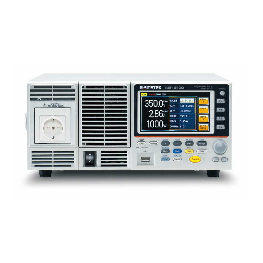
- Page 8 This chapter describes the ASR-2000 power supply in a nutshell, including its main features and front / rear panel introduction. ASR-2000 ASR-2000R ASR-2000 Series Overview..........9 Series lineup ................9 Main Features ................9 Accessories ................10 Appearance ..............12 Front Panel ................12...
-
Page 9: Getting Started
GETTING STARTED ASR-2000 Series Overview Series lineup The ASR-2000 series consists of 4 models, the ASR-2050, ASR-2100, ASR-2050R and ASR-2100R, differing only in capacity and front panel output. Note that throughout the programming manual, the term “ASR-2000” refers to any of the models, unless stated otherwise. -
Page 10: Accessories
ASR-2000 Programming Manual Include sine, square, triangle, arbitrary and DC Features output waveforms Variable voltage, frequency and current limiter Harmonic voltage and current analysis ability Excellent and feature-rich measurement capacity Sequence and simulate function External input amplification ... - Page 11 GETTING STARTED 63SC-XF101701 x 1 Remote sensing cover set GTL-123 Test leads: 1x red, 1x black GTL-246 USB CABLE (USB 2.0 Type A- Type B Cable, Approx. 1.2M) Factory Part number Description Installed Options Optional 1 RS232 + GPIB interface Optional 2 European Output Socket Optional...
-
Page 12: Appearance
ASR-2000 Programming Manual Appearance Front Panel Item Index Description Power switch button USB interface connector (A Type) LCD screen Display mode select key Function keys (blue zone) Lock/Unlock button V/V-Limit button F/F-Limit button Irms/IPK-Limit button Range key/Output mode key Menu key/On phase key Shift key... - Page 13 GETTING STARTED Test key/Output waveform key Enter key Preset key/Local mode key Cancel key/ALM CLR key Output key Scroll wheel Arrow keys Air inlet Hardcopy key Output socket (ASR-2100/2050 only) Item Description Power Switch Turn on the mains power USB A Port The USB port is used for data transfers and upgrading software.
- Page 14 ASR-2000 Programming Manual Function Keys Assigned to the functions displayed on the right side of the screen Lock/Unlock Key Used to lock or unlock the front panel keys except output key. Simply press to lock, whilst long press to unlock. Shift Key Turns on the shift state, which enables shortcut operations with an icon...
- Page 15 GETTING STARTED Irms Used for setting the maximum output current IPK-Limit Used to set the peak output current limit value Range Key Switches between the 100V, 200V and AUTO ranges Output Mode Selects between the AC+DC-INT, AC-INT, DC-INT, AC+DC-EXT, AC-EXT, AC+DC- ADD, AC-ADD, AC+DC-Sync and AC-Sync modes Menu Key...
- Page 16 Used to navigate menu items or for increment/decrement values one step at a time. Arrow Keys The arrow keys are used to select the digit power of a value that is being edited Air Inlet Air inlet for cooling the inside of the ASR-2000 series...
- Page 17 GETTING STARTED Output Socket Output voltage socket, which has 2 versions in accordance with different regions: Universal and European types, in front panel. (only available for ASR-2100/2050)
-
Page 18: Rear Panel
ASR-2000 Programming Manual Rear Panel Item Index Description Line input Output terminal Remote sensing input terminal Exhaust fan External I/O connector External signal input/ External synchronized signal input USB interface connector (B Type) Ethernet (LAN) connector Optional 1 interfaces (RS232C & GPIB connectors) - Page 19 GETTING STARTED Item Description Line Input AC inlet Output Terminal Output voltage terminal (M3 screw type, 10 ~ 18 AWG) Remote Sensing Compensation of load wire voltage Input Terminal drop. Only +S and –S are available for compensation. N.C. terminals are N/A.
- Page 20 ASR-2000 Programming Manual External Signal Synchronizing the output Input Connector frequency with this external input signal for SYNC or outputting the amplified external signal with this external input signal for EXT and ADD. USB port for controlling the ASR- 2000 remotely Ethernet Port The Ethernet port is used for remote control...
-
Page 21: Remote Control
REMOTE CONTROL EMOTE CONTROL This chapter describes basic configuration of IEEE488.2 based remote control. Interface Configuration ..........22 Configure Ethernet Connection ..........22 USB Remote Interface ............23 USB Remote Control Function Check ........24 RS-232 Remote Interface (Optional 1) ........25 RS232 Remote Control Function Check....... -
Page 22: Interface Configuration
ASR-2000 Programming Manual Interface Configuration Configure Ethernet Connection The Ethernet interface can be configured for a number of different applications. Ethernet can be configured for basic remote control or monitoring using a web server or it can be configured as a socket server. -
Page 23: Usb Remote Interface
REMOTE CONTROL ON, OFF DHCP 6. If DHCP was set to OFF, configure the remaining LAN parameters. IP Address Subnet Mask Gateway DNS Server Socket Port Socket Port is fixed to 2268. Note LAN configuration - 1 LAN configuration - 2 7. -
Page 24: Usb Remote Control Function Check
ASR-2000 Programming Manual 2. Press the Menu key. The Menu setting will appear on the display. 3. Use the scroll wheel to go to item 4, USB Device 4. If the connection is successful Connection Status will change from Offline to Online. 5. -
Page 25: Remote Interface (Optional 1)
REMOTE CONTROL Model number : ASR-XXXX Serial number : GXXXXXXXX Software version : XX.XX For further details, please see the programming Note manual, available on the GW Instek web site @ www.gwinstek.com. RS-232 Remote Interface (Optional 1) BD-9, male RS-232 Connector... - Page 26 ASR-2000 Programming Manual 3. Use the scroll wheel to go to item 5, RS232C and press Enter. 4. Set the RS232C relative settings. 1200, 2400, 4800, Baud rate 9600(default), 19200, 38400, 57600, 115200, 7 bits, 8 bits(default) Data bits None(default), Odd, Even Parity 1 bit(default), 2 bits Stop bits...
-
Page 27: Rs232 Remote Control Function Check
Serial number, and Software version in the following format. GW-INSTEK,ASR-XXXX,GXXXXXXXX,XX.XX Manufacturer: GW-INSTEK Model number : ASR-XXXX Serial number : GXXXXXXXX Software version : XX.XX For further details, please see the programming Note manual, available on the GW Instek web site @ www.gwinstek.com. -
Page 28: Using Realterm To Establish A Remote Connection
ASR-2000 Programming Manual Using Realterm to Establish a Remote Connection Realterm is a terminal program that can be used Background to communicate with a device attached to the serial port of a PC or via an emulated serial port via USB. The following instructions apply to version 2.0.0.70. - Page 29 REMOTE CONTROL If using USB, the baud rate, stop bit and parity settings can be viewed by right-clicking the connected device and selecting the Properties option. 5. Start Realterm on the PC as an administrator. Click: Start menu>All Programs>RealTerm>realterm Tip: to run as an administrator, you can right click the Realterm icon in the Windows Start menu and select the Run as Administrator option.
- Page 30 ASR-2000 Programming Manual For USB, the baud rate should be fixed to 115,200. Note 8. Click on the Send tab. In the EOL configuration, check on the +LF check boxes. Enter the query: *idn? Click on Send ASCII. 9. The terminal display will return the following:...
-
Page 31: Gpib Remote Interface (Optional 1)
REMOTE CONTROL GW-INSTEK,ASR-XXXX,GXXXXXXXX,XX.XX (manufacturer, model, serial number, software version) 10. If Realterm fails to connect to the ASR-2000, please check all the cables and settings and try again. GPIB Remote Interface (Optional 1) 1. Connect a GPIB cable from GPIB the PC to the GPIB port on Configuration the rear panel. -
Page 32: Gpib Function Check
ASR-2000 Programming Manual Maximum 15 devices altogether, 20m cable GPIB Constraints length, 2m between each device Unique address assigned to each device At least 2/3 of the devices turned On No loop or parallel connection The standard accessory does Not include GPIB data Note cable. - Page 33 REMOTE CONTROL 2. From the Configuration panel access; My System>Devices and Interfaces>GPIB0 3. Press the Scan for Instruments button. 4. In the Connected Instruments panel the ASR- 2000 should be detected as Instrument 0 with the address the same as that configured on the ASR-2000.
-
Page 34: Web Server Remote Control Function Check
ASR-2000 Programming Manual 8. Click on the Query button to send the *IDN? query to the instrument. 9. The instrument identification string will be returned to the buffer area: GW-INSTEK,ASR-XXXX,GXXXXXXXX,XX.XX (manufacturer, model, serial number, software version) 10. The function check is complete. Web Server Remote Control Function Check Enter the IP address of the power supply (for Functionality... -
Page 35: Socket Server Function Check
REMOTE CONTROL View the dimensions of the unit. View the operating area Example: Socket Server Function Check To test the socket server functionality, National Background Instruments Measurement and Automation Explorer can be used. This program is available on the NI website, www.ni.com., via a search for the VISA Run-time Engine page, or “downloads”... - Page 36 ASR-2000 Programming Manual 2. From the Configuration panel access; My System>Devices and Interfaces>Network Devices 3. Press Add New Network Device>Visa TCP/IP Resource… 4. Select Manual Entry of Raw Socket from the popup window.
- Page 37 REMOTE CONTROL 5. Enter the IP address and the port number of the ASR-2000. The port number is fixed at 2268. 6. Double click the Validate button and press Next. 7. Next configure the Alias (name) of the ASR- 2000 connection. In this example the Alias is:...
- Page 38 ASR-2000 Programming Manual 8. Click finish. 9. The IP address of the power supply will now appear under Network Devices in the configuration panel. Select this icon now. 10. Press Open VISA Test Panel. 11. Click the Configuration Icon. Under the IO Settings tab check Enable Termination Character.
- Page 39 *IDN?\n is entered in the Select or Enter Command drop box. 13. Click Query. The ASR-2000 will return the machine identification string into the buffer area: GW-INSTEK,ASR-XXXX,GXXXXXXXX,XX.XX For further details, please see the programming Note manual, available on the GW Instek web site @ www.gwinstek.com.
-
Page 40: Command Syntax
ASR-2000 Programming Manual Command Syntax Partial compatibility Compatible IEEE488.2 Standard Partial compatibility SCPI, 1999 SCPI commands follow a tree-like structure, Command organized into nodes. Each level of the command Structure tree is a node. Each keyword in a SCPI command represents each node in the command tree. - Page 41 REMOTE CONTROL A query is a simple or Query compound command followed by a question mark (?). A parameter (data) is returned. meas:curr? Example Two or more commands on the Compound same command line. Compound commands are separated with either a semi-colon (;) or a semi- colon and a colon (;:).
- Page 42 ASR-2000 Programming Manual Command Forms Commands and queries have two different forms, long and short. The command syntax is written with the short form of the command in capitals and the remainder (long form) in lower case. The commands can be written in capitals or lower-case, just so long as the short or long forms are complete.
- Page 43 REMOTE CONTROL <NR1> integers 0, 1, 2, 3 <NR2> decimal 0.1, 3.14, 8.5 numbers <NR3> floating point 4.5e-1, 8.25e+1 <NRf> any of NR1, 2, 3 1, 1.5, 4.5e-1 <block data> Definitive length arbitrary block data. A single decimal digit followed by data. The decimal digit specifies how many 8-bit data bytes follow.
-
Page 44: Command List
ASR-2000 Programming Manual Command List Common *CLS ................50 Commands *ESE ................50 *ESR ................51 *IDN ................51 *OPC ................51 *RCL ................52 *RST ................52 *SAV ................52 *SRE ................53 *STB ................53 *WAI................53 Data/Trace :DATA|TRACe:SEQuence:CLEar ...... - Page 45 REMOTE CONTROL :MEASure[:SCALar]:POWer[:AC][:REAL] ..61 :MEASure[:SCALar]:VOLTage[:RMS] ....61 :MEASure[:SCALar]:VOLTage:AVERage .... 62 :MEASure[:SCALar]:VOLTage:HIGH ....62 :MEASure[:SCALar]:VOLTage:LOW ....62 :MEASure[:SCALar]: VOLTage:HARMonic[:RMS] ..62 :MEASure[:SCALar]: VOLTage:HARMonic:RATio ... 63 :MEASure:CONFigure:SENSing ......63 :MEMory:RCL ............64 Memory Commands :MEMory:SAV ............64 :OUTPut[:STATe] ............ 65 Output Commands :OUTPut:PON ............
- Page 46 ASR-2000 Programming Manual :STATus:LOCK:PTRansition ........74 :SYSTem:BEEPer:STATe ......... 76 System Commands :SYSTem:COMMunicate:GPIB[:SELF]:ADDRess 76 :SYSTem:COMMunicate:LAN:DHCP ....76 :SYSTem:COMMunicate:LAN:DNS ..... 77 :SYSTem:COMMunicate:LAN:GATeway .... 77 :SYSTem:COMMunicate:LAN:IPADdress ... 77 :SYSTem:COMMunicate:LAN:MAC ....78 :SYSTem:COMMunicate:LAN:SMASk ....78 :SYSTem:COMMunicate:RLSTate ......79 :SYSTem:COMMunicate:SERial[:RECeive] :TRANsmit:BAUD ........... 79 :SYSTem:COMMunicate:SERial[:RECeive] :TRANsmit:BITS ............80 :SYSTem:COMMunicate:SERial[:RECeive] :TRANsmit:PARity ..........
- Page 47 REMOTE CONTROL [:SOURce]:FREQuency:LIMit:HIGH ....90 [:SOURce]:FREQuency:LIMit:LOW ...... 90 [:SOURce]:FREQuency[:IMMediate] ....91 [:SOURce]:FUNCtion[:SHAPe][:IMMediate] ..91 [:SOURce]:FUNCtion:THD:FORMat ....92 [:SOURce]:MODE ............ 93 [:SOURce]:PHASe:STARt:STATe ......94 [:SOURce]:PHASe:STOP:STATe ......94 [:SOURce]:PHASe:STARt[:IMMediate] ....95 [:SOURce]:PHASe:STOP[:IMMediate] ....95 [:SOURce]:READ ............. 96 [:SOURce]:VOLTage:RANGe ........ 96 [:SOURce]:VOLTage:LIMit:RMS ......97 [:SOURce]:VOLTage:LIMit:PEAK ......
- Page 48 ASR-2000 Programming Manual :STOP[:IMMediate] ..........110 [:SOURce]:SIMulation:ABNormal:TIME ... 110 [:SOURce]:SIMulation:ABNormal:VOLTage..111 [:SOURce]:SIMulation:CSTep ......111 [:SOURce]:SIMulation:INITial:CODE....112 [:SOURce]:SIMulation:INITial:FREQuency ..112 [:SOURce]:SIMulation:INITial:PHASe :STARt:ENABle ............113 [:SOURce]:SIMulation:INITial:PHASe :STARt[:IMMediate] ..........113 [:SOURce]:SIMulation:INITial:PHASe :STOP:ENABle ............114 [:SOURce]:SIMulation:INITial:PHASe :STOP[:IMMediate] ..........114 [:SOURce]:SIMulation:INITial:VOLTage ... 115 [:SOURce]:SIMulation:NORMal<1|2>:CODE .. 115 [:SOURce]:SIMulation:NORMal1:FREQuency ..
- Page 49 REMOTE CONTROL :DISPlay[:WINDow]:DESign:MODE ....124 Display Commands :DISPlay[:WINDow]:MEASure :SOURce<1|2|3> ..........124...
-
Page 50: Cls
ASR-2000 Programming Manual Common Commands *CLS ................50 *ESE ................50 *ESR ................51 *IDN ................51 *OPC ................51 *RCL ................52 *RST ................52 *SAV ................52 *SRE ................53 *STB ................53 *WAI ................. 53 *CLS The *CLS command clears all the event registers, Description including the status byte, event status and error queue. -
Page 51: Esr
REMOTE CONTROL *ESR Query Queries the Standard Event Status (Event) Description register. The Event Status register is cleared after it is read. Query Syntax *ESR? Returns the bit sum of the Standard Return parameter <NR1> Event Status (Event) register and clears the register. -
Page 52: Rcl
ASR-2000 Programming Manual *RCL Recalls the contents stored in memory slot M0 ~ Description M9. These memory slots are mapped to the preset settings. Syntax *RCL {<NR1>|MINimum|MAXimum} 0 ~ 9 (as memory M0 ~ M9) Parameter <NR1> Recalls the M0 memory contents. Recalls the M9 memory contents. -
Page 53: Sre
REMOTE CONTROL *SRE Query Sets or queries the Service Request Enable register. Description The Service Request Enable register determines which registers of the Status Byte register are able to generate service requests. Syntax *SRE <NR1> Query Syntax *SRE? 0~255 Parameter <NR1>... -
Page 54: Data/Trace :Data|Trace:sequence:clear
ASR-2000 Programming Manual Trace/Data Commands The TRACE and DATA node for the following Note commands are functionally equivalent. :DATA|TRACe:SEQuence:CLEar ......54 :DATA|TRACe:SEQuence:RECall ....... 54 :DATA|TRACe:SEQuence:STORe ....... 55 :DATA|TRACe:SIMulation:CLEar ....... 55 :DATA|TRACe:SIMulation:RECall ...... 56 :DATA|TRACe:SIMulation:STORe ...... 56 :DATA|TRACe:WAVe:CLEar ......56 :DATA|TRACe:WAVe[:DATA] ......57 :DATA|TRACe:SEQuence:CLEar Clears the sequence data for the selected save Description... -
Page 55: Data|Trace:sequence:store
REMOTE CONTROL 0~9 (Seq0 ~ Seq9). Parameter <NR1> Example :DATA:SEQ:REC 1 Loads the data from Seq1. :DATA|TRACe:SEQuence:STORe Saves the sequence data. This command is the Description equivalent to saving a sequence memory in Sequence mode. Syntax :DATA|TRACe:SEQuence:STORe {<NR1>|MINimum|MAXimum} 0~9 (Seq0 ~ Seq9). Parameter <NR1>... -
Page 56: Data|Trace:simulation:recall
ASR-2000 Programming Manual :DATA|TRACe:SIMulation:RECall Loads the simulation data. This command is the Description equivalent to recalling a simulation memory in the Simulation mode (SIM0~SIM9). Syntax :DATA|TRACe:SIMulation:RECall {<NR1>|MINimum|MAXimum} 0~9 (SIM0 ~ SIM9). Parameter <NR1> Example :DATA:SIM:REC 1 Loads the data from SIM1. :DATA|TRACe:SIMulation:STORe Saves the simulation data. -
Page 57: Data|Trace:wave[:Data]
REMOTE CONTROL 1~16 (ARB1 ~ ARB16). Parameter <NR1> 1(1ARB1) 16(ARB16) Example :DATA:WAV:CLE 13 Clears the wave data from ARB13. :DATA|TRACe:WAVe[:DATA] Sets the arbitrary wave. Description Syntax :DATA|TRACe:WAVe[:DATA] {<NR1>|<Binary Data>} 1 – 16 (ARB 1 – 16) Parameter <NR1> Binary Data includes the #48192<DAB>...<DAB> Indicates the block data is sent. -
Page 58: Measure :Measure[:Scalar]:Current:cfactor
ASR-2000 Programming Manual Measure Commands :MEASure[:SCALar]:CURRent:CFACtor ..... 58 :MEASure[:SCALar]:CURRent:HIGH ....58 :MEASure[:SCALar]:CURRent:LOW ....59 :MEASure[:SCALar]:CURRent:PEAK:CLEar ..59 :MEASure[:SCALar]:CURRent:PEAK:HOLD ..59 :MEASure[:SCALar]:CURRent[:RMS] ....59 :MEASure[:SCALar]:CURRent:AVERage .... 60 :MEASure[:SCALar]:CURRent:HARMonic[:RMS] ... 60 :MEASure[:SCALar]:CURRent:HARMonic:RATio ... 60 :MEASure[:SCALar]:FREQuency ......60 :MEASure[:SCALar]:POWer[:AC]:APParent ..61 :MEASure[:SCALar]:POWer[:AC]:PFACtor ..61 :MEASure[:SCALar]:POWer[:AC]:REACtive .. -
Page 59: Measure[:Scalar]:Current:low
REMOTE CONTROL Current maximum peak value is defined as the Note: highest peak value in the complete period. Query syntax :MEASure[:SCALar]:CURRent:HIGH? Returns the Imax value in amps. Return parameter <NR2> :MEASure[:SCALar]:CURRent:LOW Query Returns the output current minimum value Description (Imin). Current minimum value is defined as the lowest Note value in the complete period. -
Page 60: Measure[:Scalar]:Current:average
ASR-2000 Programming Manual :MEASure[:SCALar]:CURRent:AVERage Query Returns the current average value (Iavg). Description Query syntax :MEASure[:SCALar]:CURRent:AVERage? Returns the current average value in Return <NR2> amps. :MEASure[:SCALar]:CURRent:HARMonic[:RMS] Query Returns 41 values covering Total and order 1 to 40 Description current (Irms) in harmonic. (Only AC-INT and 50 /60 Hz Active) Query syntax :MEASure[:SCALar]:CURRent:HARMonic[:RMS]? -
Page 61: Measure[:Scalar]:Power[:Ac]:Apparent
REMOTE CONTROL :MEASure[:SCALar]:POWer[:AC]:APParent Query Returns the apparent power (S). Description Query syntax :MEASure[:SCALar]:POWer[:AC]:APParent? Returns the apparent power in VA. Return <NR2> :MEASure[:SCALar]:POWer[:AC]:PFACtor Query Returns the power factor (PF). Description Query syntax :MEASure[:SCALar]:POWer[:AC]:PFACtor? Returns the power factor. Return <NR2> :MEASure[:SCALar]:POWer[:AC]:REACtive Query Returns the reactive power (Q). -
Page 62: Measure[:Scalar]:Voltage:average
ASR-2000 Programming Manual :MEASure[:SCALar]:VOLTage:AVERage Query Returns the voltage average value (Vavg). Description Query syntax :MEASure[:SCALar]:VOLTage:AVERage? Returns the voltage average value in Return <NR2> volts. :MEASure[:SCALar]:VOLTage:HIGH Query Returns the output voltage maximum peak value Description (Vmax). Voltage maximum peak value is defined as the Note highest peak value in the complete period. -
Page 63: Measure[:Scalar]: Voltage:harmonic:ratio
REMOTE CONTROL Returns the entire 41 values Return <NR2>,<NR2 containing Total and order 1 to 40 >,<NR2>, <NR2>…, etc. voltage (Vrms) in harmonic. :MEASure[:SCALar]: VOLTage:HARMonic:RATio Query Returns 41 values covering Total and order 1 to 40 Description voltage (Ratio) in harmonic. (Only AC-INT and 50 /60 Hz Active) Query syntax :MEASure[:SCALar]: VOLTage:HARMonic:RATio? - Page 64 ASR-2000 Programming Manual Memory Commands :MEMory:RCL ............64 :MEMory:SAV............64 :MEMory:RCL Recalls the settings from memory slot M0~M9. Description These memory slots are mapped to the preset settings. Equivalent to the *RCL command. Syntax :MEMory:RCL {<NR1>|MINimum|MAXimum} Parameter <NR1> MINimum MAXimum Example :MEMory:RCL Recall the settings to M1.
- Page 65 REMOTE CONTROL Output Commands :OUTPut[:STATe] ............ 65 :OUTPut:PON ............65 :OUTPut:PROTection:CLEar ......... 66 :OUTPut:RELay ............66 :OUTPut[:STATe] Query Sets or queries the output state of power source. Description Syntax :OUTPut[:STATe] {<bool>|OFF|ON} Query Syntax :OUTPut[:STATe]? Turns the output off. Parameter OFF | 0 Turns the output on.
- Page 66 ASR-2000 Programming Manual Example :OUTPut:PON 2 Sets sequence function on at power-on. :OUTPut:PROTection:CLEar The Command will clear alarms like Over Description Current, Over Peak Current, Output Over-Power, Output Short, Output Overvoltage, Sensing Voltage Error. Syntax :OUTPut:PROTection:CLEar :OUTPut:RELay Query Sets or queries the output relay of power source. Description Syntax :OUTPut:RELay {<bool>|OFF|ON}...
-
Page 67: Status:operation:condition
REMOTE CONTROL Status Commands :STATus:OPERation:CONDition ......67 :STATus:OPERation:ENABle ......... 68 :STATus:OPERation[:EVENt] ........ 68 :STATus:OPERation:NTRansition......68 :STATus:OPERation:PTRansition ......68 :STATus:QUEStionable[:EVENt] ......69 :STATus:QUEStionable:CONDition ..... 69 :STATus:QUEStionable:ENABle ......69 :STATus:QUEStionable:NTRansition ....70 :STATus:QUEStionable:PTRansition ....70 :STATus:PRESet ............70 :STATus:WARNing:CONDition ......71 :STATus:WARNing:ENABle........71 :STATus:WARNing[:EVENt] ......... -
Page 68: Status:operation:enable
ASR-2000 Programming Manual :STATus:OPERation:ENABle Query Sets or queries the bit sum of the Operation Status Description Enable register. Syntax :STATus:OPERation:ENABle <NR1> Query Syntax :STATus:OPERation:ENABle? 0~32767 Parameter <NR1> 0~32767 Return parameter <NR1> :STATus:OPERation[:EVENt] Query Queries the Operation Status Event register and Description clears the contents of the register. -
Page 69: Status:questionable[:Event]
REMOTE CONTROL Syntax :STATus:OPERation:PTRansition <NR1> :STATus:OPERation:PTRansition? 0~32767 Parameter <NR1> 0~32767 Return parameter <NR1> :STATus:QUEStionable[:EVENt] Query Queries the bit sum of the Questionable Status Description Event register. This query will also clear the contents of the register. Query Syntax :STATus:QUEStionable[:EVENt]? 0~32767 Return parameter <NR1>... -
Page 70: Status:questionable:ntransition
ASR-2000 Programming Manual :STATus:QUEStionable:NTRansition Query Sets or queries the bit sum of the negative Description transition filter of the Questionable Status register. Syntax :STATus:QUEStionable:NTRansition <NR1> Query Syntax :STATus:QUEStionable:NTRansition? 0~32767 Parameter <NR1> 0~32767 Return parameter <NR1> :STATus:QUEStionable:PTRansition Query Sets or queries the bit sum of the positive Description transition filter of the Questionable Status register. -
Page 71: Status:warning:condition
REMOTE CONTROL Operation Status Negative Transition 0x0000 WARNing Status Enable 0x0000 WARNing Status Positive Transition 0x7FFF WARNing Status Negative Transition 0x0000 System Lock Status Enable 0x0000 System Lock Status Positive Transition 0x7FFF System Lock Status Negative Transition 0x0000 Summary: The Questionable Status Enable registers, the Operation Status Enable registers, Warning Status registers and System Lock Status registers are both reset to 0. -
Page 72: Status:warning[:Event]
ASR-2000 Programming Manual Syntax :STATus:WARNing:ENABle <NR1> Query Syntax :STATus:WARNing:ENABle? 0~32767 Parameter <NR1> 0~32767 Return parameter <NR1> :STATus:WARNing[:EVENt] Query Queries the Warning Status Event register and Description clears the contents of the register. Syntax :STATus:WARNing[:EVENt]? Returns the bit sum of the Warning Return <NR1>... -
Page 73: Status:lock:condition
REMOTE CONTROL :STATus:LOCK:CONDition Query Queries the System Lock Status register. This Description query will not clear the register. Syntax :STATus:LOCK:CONDition? Returns the bit sum of the System Lock Return <NR1> Status register. (0~32767) :STATus:LOCK:ENABle Query Sets or queries the bit sum of the System Lock Description Status Enable register. -
Page 74: Status:lock:ptransition
ASR-2000 Programming Manual 0~32767 Return parameter <NR1> :STATus:LOCK:PTRansition Query Sets or queries the bit sum of the positive Description transition filter of the System Lock Status register. Syntax :STATus:LOCK:PTRansition <NR1> :STATus:LOCK:PTRansition? 0~32767 Parameter <NR1> 0~32767 Return parameter <NR1>... - Page 75 REMOTE CONTROL System Function Commands :SYSTem:BEEPer:STATe ......... 76 :SYSTem:COMMunicate:GPIB[:SELF]:ADDRess 76 :SYSTem:COMMunicate:LAN:DHCP ....76 :SYSTem:COMMunicate:LAN:DNS ..... 77 :SYSTem:COMMunicate:LAN:GATeway .... 77 :SYSTem:COMMunicate:LAN:IPADdress ... 77 :SYSTem:COMMunicate:LAN:MAC ....78 :SYSTem:COMMunicate:LAN:SMASk ....78 :SYSTem:COMMunicate:RLSTate ......79 :SYSTem:COMMunicate:SERial[:RECeive] :TRANsmit:BAUD ........... 79 :SYSTem:COMMunicate:SERial[:RECeive] :TRANsmit:BITS ............80 :SYSTem:COMMunicate:SERial[:RECeive] :TRANsmit:PARity ..........
-
Page 76: System:beeper:state
ASR-2000 Programming Manual :SYSTem:BEEPer:STATe Query Sets or queries the buzzer state on/off. Description Syntax :SYSTem:BEEPer:STATe {<bool>|OFF|ON} Query Syntax :SYSTem:BEEPer:STATe? Turns the buzzer off. Parameter OFF | 0 Turns the buzzer on. ON | 1 Returns the buzzer status. Return parameter <bool> :SYSTem:COMMunicate:GPIB[:SELF]:ADDRess Query Sets or queries the GPIB address. -
Page 77: System:communicate:lan:dns
REMOTE CONTROL DHCP on ON | 1 Returns the DHCP status. Return parameter <bool> :SYSTem:COMMunicate:LAN:DNS Query Sets or queries the DNS address. Description The setting will only be valid after the power has Note been cycled. Syntax :SYSTem:COMMunicate:LAN:DNS <string> Query Syntax :SYSTem:COMMunicate:LAN:DNS? Parameter/Return <string>... -
Page 78: System:communicate:lan:mac
ASR-2000 Programming Manual The setting will only be valid after the power has Note been cycled. Syntax :SYSTem:COMMunicate:LAN:IPADdress <string> Query Syntax :SYSTem:COMMunicate:LAN:IPADdress? Parameter/Return <string> LAN IP address in string format ( “address”) Applicable ASCII characters: 20H to 7EH Example SYST:COMM:LAN:IPAD “172.16.5.111” Sets the IP address to 172.16.5.111. -
Page 79: System:communicate:rlstate
REMOTE CONTROL :SYSTem:COMMunicate:RLSTate Query Enables or disables local/remote state of the Description instrument. Syntax :SYSTem:COMMunicate:RLSTate {LOCal | REMote | RWLock | LREMote} Query Syntax :SYSTem:COMMunicate:RLSTate? All keys are valid. This instrument is Parameter/Return LOCal controlled by the front panel controls. parameter REMote All keys are invalid, except for the [local] key and the ability to turn the output off. -
Page 80: System:communicate:serial[:Receive]
ASR-2000 Programming Manual Example SYST:COMM:SER:TRAN:BAUD? 9600 Returns the baud rate settings. :SYSTem:COMMunicate:SERial[:RECeive] :TRANsmit:BITS Query Sets or queries the UART number of data bits. Description The setting will only be valid after the power has Note been cycled. Syntax :SYSTem:COMMunicate:SERial[:RECeive]:TRANsmit :BITS <NR1> Query Syntax :SYSTem:COMMunicate:SERial[:RECeive]:TRANsmit :BITS? -
Page 81: Transmit:sbits
REMOTE CONTROL Query Syntax :SYSTem:COMMunicate:SERial[:RECeive]:TRANsmit :PARity? No parity Parameter NONE Odd parity Even parity EVEN No parity Return parameter +0 Odd parity Even parity Example SYST:COMM:SER:TRAN:PARity? Indicates that no parity is used for the UART connection. :SYSTem:COMMunicate:SERial[:RECeive] :TRANsmit:SBITs Query Sets or queries the number of stop bits used for Description the UART connection. -
Page 82: System:communicate:tcpip:control
ASR-2000 Programming Manual :SYSTem:COMMunicate:TCPip:CONTrol Query Queries the socket port number. Description Query Syntax :SYSTem:COMMunicate:TCPip:CONTrol? 0000 ~ 9999 Return parameter <NR1> Example SYST:COMM:TCP:CONT? 2268 Returns the socket port number. :SYSTem:COMMunicate:USB:FRONt:STATe Query Queries the front panel USB-A port state. Description Query Syntax :SYSTem:COMMunicate:USB:FRONt:STATe? <NR1>Absent Return parameter +0... -
Page 83: System:configure:extio[:State]
REMOTE CONTROL Query Syntax :SYSTem:CONFigure[:MODE]? CONTinuous | 0 Continuous mode (normal Parameter operating mode) Sequence mode SEQuence | 1 Simulation mode SIMulation | 2 Return parameter <NR1> Continuous mode (normal CONT operating mode) Sequence mode Simulation mode :SYSTem:CONFigure:EXTio[:STATe] Query Sets or queries the external control state on/off. Description Syntax :SYSTem:CONFigure:EXTio[:STATe] {<bool>|OFF|ON}... -
Page 84: System:error:enable
ASR-2000 Programming Manual :SYSTem:ERRor:ENABle Query Clears the Error Queue and enables all error Description messages to be placed in the System Error Queue. Syntax :SYSTem:ERRor:ENABle :SYSTem:HOLD:STATe Query Sets or queries the freeze hold state on/off. Description Syntax :SYSTem:HOLD:STATe {<bool>|OFF|ON} Query Syntax :SYSTem:HOLD:STATe? Turns the freeze hold off. -
Page 85: System:reboot
REMOTE CONTROL Panel keys unlocked Parameter OFF | 0 Panel keys locked ON | 1 Returns the key lock status. Return parameter <bool> :SYSTem:REBoot Reboots the ASR system. Description Syntax :SYSTem:REBoot :SYSTem:SLEW:MODE Query Sets or queries slew mode setting. Description Syntax :SYSTem:SLEW:MODE {<bool>|TIME|SLOPe} Query Syntax... - Page 86 ASR-2000 Programming Manual :SYSTem:VUNit? Example Returns the V Unit(TRI, ARB) setting.
-
Page 87: [:Source]:Current:limit:peak:high
REMOTE CONTROL Source Commands [:SOURce]:CURRent:LIMit:PEAK:HIGH ..... 87 [:SOURce]:CURRent:LIMit:PEAK:LOW ....88 [:SOURce]:CURRent:LIMit:RMS[:AMPLitude] ... 88 [:SOURce]:CURRent:LIMit:PEAK:MODE.... 89 [:SOURce]:CURRent:LIMit:RMS:MODE ....89 [:SOURce]:FREQuency:LIMit:HIGH ....90 [:SOURce]:FREQuency:LIMit:LOW ...... 90 [:SOURce]:FREQuency[:IMMediate] ....91 [:SOURce]:FUNCtion[:SHAPe][:IMMediate] ..91 [:SOURce]:FUNCtion:THD:FORMat ....92 [:SOURce]:MODE ............ 93 [:SOURce]:PHASe:STARt:STATe ......94 [:SOURce]:PHASe:STOP:STATe ......94 [:SOURce]:PHASe:STARt[:IMMediate] .... -
Page 88: [:Source]:Current:limit:peak:low
ASR-2000 Programming Manual Ipk-High Limit in Arms. Parameter <NR2> Minimum settable peak current high limit MINimum Maximum settable peak current high limit MAXimum Returns the Ipk-High Limit value Return parameter <NR2> Example CURR:LIM:PEAK:HIGH? +42.0000 Returns the peak current high limit as +42.0A. [:SOURce]:CURRent:LIMit:PEAK:LOW Query Sets or queries the Ipk-Low Limit parameter for... -
Page 89: [:Source]:Current:limit:peak:mode
REMOTE CONTROL Irms in A. Parameter <NR2> Minimum settable current MINimum Maximum settable current MAXimum Returns the Irms. Return parameter <NR2> Example :CURR:LIM:RMS? +10.5000 Returns the Irms setting. [:SOURce]:CURRent:LIMit:PEAK:MODE Query Sets or queries Ipk limit enabled or disabled. Description Syntax [:SOURce]:CURRent:LIMit:PEAK:MODE {<bool>|OFF|ON} Query Syntax... -
Page 90: [:Source]:Frequency:limit:high
ASR-2000 Programming Manual [:SOURce]:FREQuency:LIMit:HIGH Query Sets or queries the frequency upper limit range. Description (Only AC+DC-INT or AC-INT or AC+DC-ADD or AC-ADD Active) Syntax [:SOURce]:FREQuency:LIMit:HIGH {<NR2>|MINimum|MAXimum} Query Syntax [:SOURce]:FREQuency:LIMit:HIGH? [INimum|MAXimum] Frequency in Hz. Parameter <NR2> Minimum settable frequency MINimum Maximum settable frequency MAXimum Returns the frequency limit Return parameter <NR2>... -
Page 91: [:Source]:Frequency[:Immediate]
REMOTE CONTROL Example FREQ:LIM:LOW? +1.0000 Returns the frequency lower limit. [:SOURce]:FREQuency[:IMMediate] Query Sets or queries the frequency for the immediate Description trigger. (Only AC+DC-INT or AC-INT or AC+DC- ADD or AC-ADD Active) Syntax [:SOURce]:FREQuency[:IMMediate] {<NR2>(HZ)|MINimum|MAXimum} Query Syntax [:SOURce]:FREQuency[:IMMediate]? [MINimum|MAXimum] Frequency setting in Hz. Parameter/Return <NR2>... -
Page 92: [:Source]:Function:thd:format
ASR-2000 Programming Manual Arbitrary wave 3 ARB3 | 2 Arbitrary wave 4 ARB4 | 3 Arbitrary wave 5 ARB5 | 4 Arbitrary wave 6 ARB6 | 5 Arbitrary wave 7 ARB7 | 6 Arbitrary wave 8 ARB8 | 7 Arbitrary wave 9 ARB9 | 8 Arbitrary wave 10 ARB10 | 9... -
Page 93: [:Source]:Mode
REMOTE CONTROL IEC THD format IEC | 0 CSA THD format CSA | 1 Example :SOUR:FUNC:THD:FORM? Returns the THD format as IEC. [:SOURce]:MODE Query Sets or queries the output mode of power supply. Description Syntax [:SOURce]:MODE {<NR1>|ACDC-INT|AC-INT|DC-INT|ACDC-EXT|AC- EXT|ACDC-ADD|AC-ADD|ACDC-SYNC|AC-SYNC} Query Syntax [:SOURce]:MODE? From 0 –... -
Page 94: [:Source]:Phase:start:state
ASR-2000 Programming Manual [:SOURce]:PHASe:STARt:STATe Query Sets or queries state of start phase. (Not available Description for DC-INT, AC+DC-EXT and AC-EXT) Syntax [:SOURce]:PHASe:STARt:STATe {<bool>|FREE|FIXED} Query Syntax [:SOURce]:PHASe:STARt:STATe? |FREE (0)|FIXED (1) Parameter/ <bool> Return parameter Start phase Free FREE | 0 Start phase Fixed FIXED | 1 Example :PHAS:STAR:STAT? -
Page 95: [:Source]:Phase:start[:Immediate]
REMOTE CONTROL [:SOURce]:PHASe:STARt[:IMMediate] Query Sets or queries the start phase. (Not available for Description DC-INT, AC+DC-EXT and AC-EXT) Syntax [:SOURce]:PHASe:STARt[:IMMediate] {<NR2>|MINimum|MAXimum} Query Syntax [:SOURce]:PHASe:STARt[:IMMediate]? [MINimum|MAXimum] Start phase value Parameter/Return <NR2> parameter 0º MINimum 359.9 º MAXimum Example :PHAS:STAR 0 Sets the starting phase to 0. [:SOURce]:PHASe:STOP[:IMMediate] Query Sets or queries the off phase of the waveform. -
Page 96: [:Source]:Read
ASR-2000 Programming Manual [:SOURce]:READ Query Returns the measurement readouts. Description Query Syntax [:SOURce]:READ? <THDv>,<THDi> returns values in Return parameter <Vrms>,<Vavg>,< AC-INT mode only, whereas Vmax>,<Vmin>,<I returns Invalid in other modes. rms>,<Iavg>,<Im ax>,<Imin>,<IpkH <S>,<Q>,<PF>,<CF> returns >,<P>,<S>,<Q>,< Invalid in DC-INT mode. PF>,<CF>,<THDv <Freq>... -
Page 97: [:Source]:Voltage:limit:rms
REMOTE CONTROL Example :SOUR:VOLT:RANG? 200V Returns the voltage range as 200V. [:SOURce]:VOLTage:LIMit:RMS Query Sets or queries the voltage limit for the continuous Description operation mode. (Only AC-INT or AC-ADD or AC-Sync Active) Syntax [:SOURce]:VOLTage:LIMit:RMS {<NR2>|MINimum|MAXimum} Query Syntax [:SOURce]:VOLTage:LIMit:RMS? [MINimum|MAXimum] Vrms. Parameter <NR2>... -
Page 98: [:Source]:Voltage:limit:high
ASR-2000 Programming Manual Minimum Vpp limit MINimum MAXimum Maximum Vpp limit Returns the Vpp limit. Return parameter <NR2> Example VOLT:LIM:PEAK? +500.0000 Returns the Vpp limit. [:SOURce]:VOLTage:LIMit:HIGH Query Sets or queries the voltage high limit. (Only Description AC+DC-INT or DC-INT or AC+DC-ADD or AC+DC-Sync Active) Syntax [:SOURce]:VOLTage:LIMit:HIGH... -
Page 99: [:Source]:Voltage[:Level][:Immediate] [:Amplitude]
REMOTE CONTROL Query Syntax [:SOURce]:VOLTage:LIMit:LOW? [MINimum|MAXimum] Voltage low limit Parameter <NR2> Minimum voltage low limit MINimum Maximum voltage low limit MAXimum Returns the voltage low limit. Return parameter <NR2> Example VOLT:LIM:LOW? -500.0000 Returns the voltage low limit. [:SOURce]:VOLTage[:LEVel][:IMMediate] [:AMPLitude] Query Sets or queries the RMS voltage for the continuous Description operation mode. - Page 100 ASR-2000 Programming Manual Syntax [:SOURce]:VOLTage[:LEVel][:IMMediate]:OFFSet {<NR2>(V)|MINimum|MAXimum} Query Syntax [:SOURce]:VOLTage[:LEVel][:IMMediate]:OFFSet? [MINimum|MAXimum] Voltage offset value Parameter/Return <NR2> parameter Minimum voltage offset value MINimum Maximum voltage offset value MAXimum Example :VOLT:OFFS? +150.0000 Returns the voltage offset value as 150.0.
- Page 101 REMOTE CONTROL Sequence Commands [:SOURce]:SEQuence:CPARameter ....101 [:SOURce]:SEQuence:CSTep ........ 102 [:SOURce]:SEQuence:SPARameter ..... 102 [:SOURce]:SEQuence:STEP ........103 [:SOURce]:SEQuence:CONDition ....... 104 :TRIGger:SEQuence:SELected:EXECute .... 104 [:SOURce]:SEQuence:CPARameter Query Sets the common parameters for the Sequence Description mode. Please see the user manual for a full description of each parameter (Only Sequence Mode Active).
- Page 102 ASR-2000 Programming Manual Sync Code: LL(0) / LH(1) / HL(2) <NR1> / HH(3) Branch1 (0 ~ 999) <NR1> Branch1 on(1)/off(0) <bool>|OFF|ON Branch2 (0 ~ 999) <NR1> Branch2 on(1)/off(0) <bool>|OFF|ON Reserved (Fixed to 0) <bool> <NR2>,<NR2>,<bool>,<NR2>,<bool>,<NR1>,<NR1>, Return parameter <bool>,<NR1>,<NR1>,<bool>,<NR1>,<bool>, <bool> Returns the common parameters in the following order: Step time, on phase, on phase on/off, off phase, off phase on/off, term settings, jump step number, jump on/off, jump count, code on/off, branch1, branch1...
- Page 103 REMOTE CONTROL Syntax [:SOURce]:SEQuence:SPARameter {<NR2>,<NR1>|CONSt|KEEP|SWEep,<NR2>,<NR1>| CONSt|KEEP|SWEep,<NR2>,<NR1>|CONSt|KEEP|SW Eep,SIN,<NR1>} Query Syntax [:SOURce]:SEQuence:SPARameter? ACV setting Parameter <NR2> ACV mode: Constant(0) | Keep(1) <NR1>|CONSt| | Sweep(2) KEEP|SWEep DCV. Not applicable. This <NR2> parameter will be ignored. DCV mode: Constant(0) | Keep(1) <NR1>|CONSt| | Sweep(2) KEEP|SWEep Frequency <NR2>...
- Page 104 ASR-2000 Programming Manual Syntax [:SOURce]:SEQuence:STEP {<NR1>|MINimum|MAXimum} Query Syntax [:SOURce]:SEQuence:STEP? [MINimum|MAXimum] Step number Parameter/Return <NR1> parameter Minimum step number MINimum Maximum step number MAXimum Example :SEQ:STEP 1 Sets the step number to 1. [:SOURce]:SEQuence:CONDition Query Returns the sequence status.(Only Sequence Mode Description Active) Query Syntax...
- Page 105 REMOTE CONTROL Example TRIG:SEQ:SEL:EXEC STAR Starts sequence execution.
- Page 106 ASR-2000 Programming Manual Simulate Commands [:SOURce]:SIMulation:CONDition ..... 107 [:SOURce]:SIMulation:ABNormal:CODE ..107 [:SOURce]:SIMulation:ABNormal:FREQuency 108 [:SOURce]:SIMulation:ABNormal:PHASe :STARt:ENABle ............108 [:SOURce]:SIMulation:ABNormal:PHASe :STARt[:IMMediate] ..........109 [:SOURce]:SIMulation:ABNormal:PHASe :STOP:ENABle ............109 [:SOURce]:SIMulation:ABNormal:PHASe :STOP[:IMMediate] ..........110 [:SOURce]:SIMulation:ABNormal:TIME ... 110 [:SOURce]:SIMulation:ABNormal:VOLTage ..111 [:SOURce]:SIMulation:CSTep ......111 [:SOURce]:SIMulation:INITial:CODE ....112 [:SOURce]:SIMulation:INITial:FREQuency ..
-
Page 107: [:Source]:Simulation:condition
REMOTE CONTROL [:SOURce]:SIMulation:NORMal1:VOLTage ..119 [:SOURce]:SIMulation:REPeat:COUNt ....119 [:SOURce]:SIMulation:REPeat:ENABle ....120 [:SOURce]:SIMulation:TRANsition<1|2> :TIME ............... 120 [:SOURce]:SIMulation:TRANsition<1|2> :CODE ..............121 :TRIGger:SIMulation:SELected:EXECute ... 121 [:SOURce]:SIMulation:CONDition Query Returns the simulation status. (Only Simulation Description Mode Active) Query Syntax [:SOURce]:SIMulation:CONDition? 0 (Idle mode) Current simulation 1 (Run mode) Return parameter <NR1>... -
Page 108: [:Source]:Simulation:abnormal:frequency
ASR-2000 Programming Manual 3 (HH) MAXimum Example SIM:ABN:CODE 1 [:SOURce]:SIMulation:ABNormal:FREQuency Query Sets or queries the frequency of the abnormal step Description of the simulation mode (Only Simulation Mode Active). Syntax [:SOURce]:SIMulation:ABNormal:FREQuency {<NR2>|MINimum|MAXimum} Query Syntax [:SOURce]:SIMulation:ABNormal:FREQuency? [MINimum|MAXimum] Frequency of abnormal step Parameter/Return <NR2>... -
Page 109: Start[:Immediate]
REMOTE CONTROL [:SOURce]:SIMulation:ABNormal:PHASe :STARt[:IMMediate] Query Sets or queries the ON Phs parameter of the Description abnormal step for the Simulation mode (Only Simulation Mode Active). Syntax [:SOURce]:SIMulation:ABNormal:PHASe:STARt [:IMMediate] {<NR2>|MINimum|MAXimum} Query Syntax [:SOURce]:SIMulation:ABNormal:PHASe:STARt [:IMMediate]? [MINimum|MAXimum] ON Phs (start phase) Parameter/Return <NR2> parameter MINimum 359.9... -
Page 110: Stop[:Immediate]
ASR-2000 Programming Manual [:SOURce]:SIMulation:ABNormal:PHASe :STOP[:IMMediate] Query Sets or queries the OFF Phs parameter of the Description abnormal step for the Simulation mode (Only Simulation Mode Active). Sets the off phase of the waveform after the Note output has been turned off. Syntax [:SOURce]:SIMulation:ABNormal:PHASe:STOP [:IMMediate] {<NR2>|MINimum|MAXimum}... -
Page 111: [:Source]:Simulation:abnormal:voltage
REMOTE CONTROL [:SOURce]:SIMulation:ABNormal:VOLTage Query Sets or queries the Vset parameter of the abnormal Description step for the Simulation mode (Only Simulation Mode Active). Syntax [:SOURce]:SIMulation:ABNormal:VOLTage {<NR2>|MINimum|MAXimum} Query Syntax [:SOURce]:SIMulation:ABNormal:VOLTage? [MINimum|MAXimum] Voltage of the abnormal step. Parameter/Return <NR2> parameter Minimum settable voltage MINimum Maximum settable voltage MAXimum... -
Page 112: [:Source]:Simulation:initial:code
ASR-2000 Programming Manual [:SOURce]:SIMulation:INITial:CODE Query Sets the external trigger output for the initial step Description parameter. This option is only applicable when in the Simulation mode (Only Simulation Mode Active). Syntax [:SOURce]:SIMulation:INITial:CODE {<NR1>|MINimum|MAXimum} Query Syntax [:SOURce]:SIMulation:INITial:CODE? [MINimum|MAXimum] 0=LL, 1=LH, 2=HL, 3=HH Parameter/Return <NR1>... -
Page 113: [:Source]:Simulation:initial:phase :
REMOTE CONTROL [:SOURce]:SIMulation:INITial:PHASe:STARt:ENA Query Enables/Disables (Fixed/Free) the ON Phs Description parameter of the initial step for the Simulation mode (Only Simulation Mode Active). Syntax [:SOURce]:SIMulation:INITial:PHASe:STARt:ENABle {<bool>|OFF|ON|FREE|FIXED} Query Syntax [:SOURce]:SIMulation:INITial:PHASe:STARt:ENABle? Disabled Parameter/Return OFF | 0 | FREE parameter Enabled ON | 1 | FIXED Example :SIM:INIT:PHAS:STAR:ENAB 1 Enable the ON Phs. -
Page 114: [:Source]:Simulation:initial:phase :
ASR-2000 Programming Manual [:SOURce]:SIMulation:INITial:PHASe:STOP :ENABle Query Enables/Disables (Fixed/Free) the OFF Phs Description parameter of the initial step for the Simulation mode (Only Simulation Mode Active). Syntax [:SOURce]:SIMulation:INITial:PHASe:STOP:ENABle {<bool>|OFF|ON|FREE|FIXED} Query Syntax [:SOURce]:SIMulation:INITial:PHASe:STOP:ENABle? Disabled Parameter/Return OFF | 0 | FREE parameter Enabled ON | 1 | FIXED Example :SIM:INIT:PHAS:STOP:ENAB 1... -
Page 115: [:Source]:Simulation:initial:voltage
REMOTE CONTROL [:SOURce]:SIMulation:INITial:VOLTage Query Sets or queries the Vset parameter of the initial Description step for the Simulation mode (Only Simulation Mode Active). Syntax [:SOURce]:SIMulation:INITial:VOLTage {<NR2>|MINimum|MAXimum} Query Syntax [:SOURce]:SIMulation:INITial:VOLTage? [MINimum|MAXimum] Voltage of the initial step. Parameter/Return <NR2> parameter Minimum settable voltage MINimum Maximum settable voltage MAXimum... -
Page 116: [:Source]:Simulation:normal1:Frequency
ASR-2000 Programming Manual [:SOURce]:SIMulation:NORMal1:FREQuency Query Sets or queries the frequency of the normal1 step Description of the simulation mode (Only Simulation Mode Active). Syntax [:SOURce]:SIMulation:NORMal1:FREQuency {<NR2>|MINimum|MAXimum} Query Syntax [:SOURce]:SIMulation:NORMal1:FREQuency? [MINimum|MAXimum] Normal 1 Parameter/Return parameter Frequency of abnormal step <NR2> Minimum frequency MINimum Maximum frequency MAXimum... -
Page 117: [:Source]:Simulation:normal<1|2> :Phase:start[:Immediate]
REMOTE CONTROL [:SOURce]:SIMulation:NORMal<1|2> :PHASe:STARt[:IMMediate] Query Sets or queries the ON Phs parameter of the Description normal1 or normal2 step for the Simulation mode (Only Simulation Mode Active). Syntax [:SOURce]:SIMulation:NORMal<1|2>:PHASe:STARt[:I MMediate] {<NR2>|MINimum|MAXimum} Query Syntax [:SOURce]:SIMulation:NORMal<1|2>:PHASe:STARt[:I MMediate]? [MINimum|MAXimum] Normal 1 or Normal 2 Parameter/Return <1|2>... -
Page 118: [:Source]:Simulation:normal<1|2> :Phase:stop[:Immediate]
ASR-2000 Programming Manual [:SOURce]:SIMulation:NORMal<1|2> :PHASe:STOP[:IMMediate] Query Sets or queries the OFF Phs parameter of the Description normal1 or normal2 step for the Simulation mode (Only Simulation Mode Active). Sets the off phase of the waveform after the Note output has been turned off. Syntax [:SOURce]:SIMulation:NORMal<1|2>:PHASe:STOP[:I MMediate] {<NR2>|MINimum|MAXimum}... - Page 119 REMOTE CONTROL Example :SIM:NORM1:TIME 1 Sets the step time to 1 second. [:SOURce]:SIMulation:NORMal1:VOLTage Query Sets or queries the Vset parameter of the normal1 Description step for the Simulation mode (Only Simulation Mode Active). Syntax [:SOURce]:SIMulation:NORMal1:VOLTage {<NR2>|MINimum|MAXimum} Query Syntax [:SOURce]:SIMulation:NORMal1:VOLTage? [MINimum|MAXimum] Normal 1 Parameter/Return parameter...
- Page 120 ASR-2000 Programming Manual [:SOURce]:SIMulation:REPeat:ENABle Query Turns the repeat function on or off for the Description Simulation mode (Only Simulation Mode Active). Syntax [:SOURce]:SIMulation:REPeat:ENABle {<bool>|OFF|ON} Query Syntax [:SOURce]:SIMulation:REPeat:ENABle? Disabled Parameter/Return OFF | 0 parameter Enabled ON | 1 Example :SIM:REP:ENAB 1 Enables the repeat function.
- Page 121 REMOTE CONTROL [:SOURce]:SIMulation:TRANsition<1|2>:CODE Query Sets the external trigger output for the transition Description step parameter. This option is only applicable when in the Simulation mode (Only Simulation Mode Active). Syntax [:SOURce]:SIMulation:TRANsition<1|2>:CODE {<NR1>|MINimum|MAXimum} Query Syntax [:SOURce]:SIMulation:TRANsition<1|2>:CODE? [MINimum|MAXimum] 0=LL, 1=LH, 2=HL, 3=HH Parameter/Return <NR1>...
- Page 122 ASR-2000 Programming Manual Input Subsystem Command :INPut:GAIN ............122 :INPut:SYNC:SOURce .......... 122 :INPut:GAIN Query Sets or queries the input gain value. (Only Description AC+DC-EXT or AC-EXT or AC+DC-ADD or AC- ADD Active) Syntax :INPut:GAIN {<NR2>(V)|MINimum|MAXimum} Query Syntax :INPut:GAIN? [MINimum|MAXimum] Input gain value Parameter/Return <NR2>...
- Page 123 REMOTE CONTROL Example :INP:SYNC:SOUR? Returns the state of sync source as EXT.
- Page 124 ASR-2000 Programming Manual Display Command :DISPlay[:WINDow]:DESign:MODE ....124 :DISPlay[:WINDow]:MEASure: SOURce<1|2|3> ........... 124 :DISPlay[:WINDow]:DESign:MODE Sets two display mode. Description Syntax :DISPlay[:WINDow]:DESign:MODE{NORMal|SIMPle} Configure setup and Measurement. Parameter MORMal All measurement times. SIMPle Example :DISP:DES:MODE NORM Sets standard normal display. :DISPlay[:WINDow]:MEASure:SOURce<1|2|3> Sets standard normal display to measurement Description items 1 –...
- Page 125 REMOTE CONTROL Example :DISP:MEAS:SOUR1 VRMS Sets measurement source 1 VRMS display.
-
Page 126: Status Register Overview
ASR-2000 Programming Manual Status Register Overview To program the ASR power supply effectively, the Status registers need to be understood. This chapter explains in detail how the Status registers are used and how to configure them. Introduction to the Status Registers The status registers are used to determine the Overview status of the power supply. -
Page 127: The Status Registers
REMOTE CONTROL The Status Registers System Lock Status Register Condition PTR/NTR Event Enable Questionable Status Register Condition PTR/NTR Event Enable Operation Status Register Output Buffer Condition PTR/NTR Event Enable Error Queue Service Status Request Byte Enable Register Register Warning Status Register Condition PTR/NTR Event... -
Page 128: Questionable Status Register Group
ASR-2000 Programming Manual Questionable Status Register Group The Questionable Status Register Group indicates Overview if any protection modes or limits have been tripped. Questionable Status Register Condition PTR/NTP Event Enable & & & & & & & & & & &... - Page 129 REMOTE CONTROL Output Short Call attention to output terminal short status. Over Ipeak+ Current or Over Ipeak- Current Positive/Negative output current peak value is excessive. Fan Failure Fan failure. Contact service center. Calibration Data Error The calibration data is abnormal or out of allowance range.
- Page 130 ASR-2000 Programming Manual The Questionable Status Condition Register Condition indicates the status of the power supply. If a bit is Register set in the Condition register, it indicates that the event is true. Reading the condition register does not change the state of the condition register. PTR/NTR Filters The PTR/NTR (Positive/Negative transition) register determines the type of transition conditions that will set the corresponding bit in...
-
Page 131: Operation Status Register Group
REMOTE CONTROL Operation Status Register Group The Operation Status Register Group indicates the Overview operating status of the power supply. Operation Status Register Condition PTR/NTP Event Enable & & & & & & & & & & & & & &... - Page 132 ASR-2000 Programming Manual PTR/NTR Filters The PTR/NTR (Positive/Negative transition) register determines the type of transition conditions that will set the corresponding bit in the Event Registers. Use the Positive transition filter to view events that change from false to positive, and use the negative transition filter to view events that change from positive to negative.
-
Page 133: Warning Status Register Group
REMOTE CONTROL Warning Status Register Group The Warning Status Register Group is a secondary Overview protection status register for the supply output. Warning Status Register Condition PTR/NTP Event Enable & & & & & & & & & & & &... - Page 134 ASR-2000 Programming Manual External Sync Frequency Error The external synchronization signal input frequency is out of the allowance range. (40Hz ~ 999.9Hz) Sensing Voltage Error Remote sense connection wire is abnormal or over maximum compensation voltage. Over Irms Current 1024 Output current RMS value is excessive Over Ipeak+ Current or Over...
- Page 135 REMOTE CONTROL PTR/NTR Filters The PTR/NTR (Positive/Negative transition) register determines the type of transition conditions that will set the corresponding bit in the Event Registers. Use the Positive transition filter to view events that change from false to positive, and use the negative transition filter to view events that change from positive to negative.
-
Page 136: System Lock Status Register Group
ASR-2000 Programming Manual System Lock Status Register Group The System Lock Status Register Group indicates Overview if system lock protection modes have been tripped. System Lock Status Register Condition PTR/NTP Event Enable & & & & & & & & &... - Page 137 REMOTE CONTROL The System Lock Status Condition Register Condition indicates the system lock status of the power Register supply. If a bit is set in the Condition register, it indicates that the event is true. Reading the condition register does not change the state of the condition register.
-
Page 138: Standard Event Status Register Group
ASR-2000 Programming Manual Standard Event Status Register Group The Standard Event Status Register Group Overview indicates if any errors have occurred. The bits of the Event register are set by the error event queue. Standard Event Status Register Event Enable &... - Page 139 REMOTE CONTROL DDE (Device Dependent Error) Device specific error. EXE (Execution Error) The EXE bit indicates an execution error due to one of the following: illegal command parameter, parameter out of range, invalid parameter, the command didn’t execute due to an overriding operation condition.
-
Page 140: Status Byte Register & Service Request Enable Register
ASR-2000 Programming Manual Status Byte Register & Service Request Enable Register The Status Byte register consolidates the status Overview events of all the status registers. The Status Byte register can be read with the *STB? query and can be cleared with the *CLS command. Output Buffer From System... - Page 141 REMOTE CONTROL RQS / MSS(Request Service / Master Summary Status) OPER (Operation Status Register) Any bits set in the Status byte register acts as a Status Byte summary register for all the three other status Register registers and indicates if there is a service request, an error in the Error Queue or data in the Output Queue.
-
Page 142: Error List
ASR-2000 Programming Manual Error List Command Errors An <error/event number> in the range [ -199 , - Overview 100 ] indicates that an IEEE 488.2 syntax error has been detected by the instrument’s parser. The occurrence of any error in this class shall cause the command error bit (bit 5) in the event status register (IEEE 488.2, section 11.5.1) to be set. - Page 143 REMOTE CONTROL -102 Syntax error An unrecognized command or data type was encountered; for example, a string was received when the device does not accept strings. The parser was expecting a separator and -103 Invalid encountered an illegal character; for example, the separator semicolon was omitted after a program message unit, MEAS:VOLT:DC?:MEASCURR:DC?
- Page 144 ASR-2000 Programming Manual The value of a numeric suffix attached to a -114 Header program mnemonic, see Syntax and Style section suffix out of range 6.2.5.2, makes the header invalid. The number of parameters received does not -115 Unexpected correspond to the number of parameters expected. number of parameters This is typically due an inconsistency with the...
-
Page 145: Execution Errors
REMOTE CONTROL A string data element was expected, but was -151 Invalid string invalid for some reason (see IEEE 488.2, 7.7.5.2); data for example, an END message was received before the terminal quote character. A string data element was encountered but was -158 String data not allowed by the device at this point in parsing. - Page 146 ASR-2000 Programming Manual inconsistent with the device’s capabilities. A valid program message could not be properly executed due to some device condition. Execution errors shall be reported by the device after rounding and expression evaluation operations have taken place. Rounding a numeric data element, for example, shall not be reported as an execution error.
-
Page 147: Device Specific Errors
REMOTE CONTROL -213 Init ignored Indicates that a request for a measurement initiation was ignored as another measurement was already in progress. Indicates that a program data element related -220 Parameter error occurred. This error message should be used error when the device cannot detect the more specific errors described for errors -221 through -229. -
Page 148: Query Errors
ASR-2000 Programming Manual message>string for positive error codes is not defined by SCPI and available to the device designer. Note that the string is not optional; if the designer does not wish to implement a string for a particular error, the null string should be sent (for example, 42,""). - Page 149 REMOTE CONTROL An attempt is being made to read data from the output queue when no output is either present or pending; Data in the output queue has been lost. Events that generate query errors shall not generate command errors, execution errors, or device-specific errors;...
-
Page 150: Appendix
ASR-2000 Programming Manual PPENDIX Factory Default Settings The following default settings are the factory configuration settings for the ASR-2000 series. For details on how to return to the factory default settings, please see the user manual. AC+DC-INT Mode ASR-2050 ASR-2050R ASR-2100... - Page 151 APPENDIX DC-INT Mode ASR-2050 ASR-2050R ASR-2100 ASR-2100R Range 100V 0.0 Vdc 5.25 A 10.50 A V Limit +/- 250.0 Vpp IPK Limit +/- 21.00 A +/- 42.00 A AC+DC-EXT Mode ASR-2050 ASR-2050R ASR-2100 ASR-2100R Range 100V GAIN 100.0 IRMS 5.25 A 10.50 A IPK Limit +/- 21.00 A...
- Page 152 ASR-2000 Programming Manual FREQ 50.00 Hz IRMS 5.25 A 10.50 A V Limit 175.0 Vrms F Limit Lo 40.0 Hz F Limit Hi 999.9 Hz IPK Limit +/- 21.00 A +/- 42.00 A ON Phs OFF Phs AC+DC-SYNC Mode ASR-2050 ASR-2050R ASR-2100 ASR-2100R Range...
- Page 153 APPENDIX Slew Rate Mode Slope Output Relay Enable THD Format External Control V Unit (TRI, ARB) ASR-2000 DHCP USB Device ASR-2000 Speed Full LCD Configuration ASR-2000 LCD Contrast LCD Brightness LCD Saturation Sequence Mode ASR-2000 Step Time 0.1000 s 0.0, CT 0.0, CT Fset 50.0, CT...
- Page 154 ASR-2000 Programming Manual ON Phs Free OFF Phs Free Wave Code RS232C Optional 1 Baudrate 9600 Databits 8bits Parity None Stopbits 1bit GPIB Optional 1 Address Default Waveform Setting ARB 1 Ramp (rising) ARB 2 Ramp (falling)
- Page 155 APPENDIX ARB 3 Sine wave, half-cycle(positive pole) ARB 4 Sine wave, half-cycle(negative pole) ARB 5 Sine wave, half-wave rectification (positive polarity)
- Page 156 ASR-2000 Programming Manual ARB 6 Sine wave, half-wave rectification(negative polarity) ARB 7 Sine wave, full-wave rectification(positive polarity) ARB 8 Sine wave, full-wave rectification(negative polarity)
- Page 157 APPENDIX ARB 9 Second order step response(damping coefficient 0.1) Second order step response(damping ARB 10 coefficient 0.2) ARB 11 Second order step response(damping coefficient 0.7)
- Page 158 ASR-2000 Programming Manual ARB 12 Second order impulse response(damping coefficient 0.1) ARB 13 Second order impulse response(damping coefficient 0.2) ARB 14 Second order impulse response(damping coefficient 0.7)
- Page 159 APPENDIX ARB 15 Exponential (rising) ARB 16 Exponential (falling) Only FW version V1.12 above can support the Note function of default waveform Setting in Factory Default Settings. Default Sequence Setting SEQ6 Momentary drop in supply voltage SEQ7 Reset test for Level1 systems with...
- Page 160 ASR-2000 Programming Manual SEQ8 Starting Profile SEQ9 Test2 Tr: 10ms, Td: 40ms Only FW version V1.12 above can support the Note function of Default Sequence Setting in Factory Default Settings.
-
Page 161: Index
INDEX NDEX Accessories ......... 10 Command list ....... 44 Command syntax ......40 Caution symbol ......4 Error list ........142 Cleaning the instrument ..... 6 Ethernet ......... 22 Default settings ......150 GPIB ..........31 Disposal instructions ....6 LAN ..........
Need help?
Do you have a question about the ASR-2000 Series and is the answer not in the manual?
Questions and answers