GW Instek APS-7100 Programming Manual
Hide thumbs
Also See for APS-7100:
- Programming manual (140 pages) ,
- User manual (193 pages) ,
- Programming manual (152 pages)

Related Manuals for GW Instek APS-7100


Summary of Contents for GW Instek APS-7100
- Page 1 All manuals and user guides at all-guides.com Programmable AC Power Source APS-7000 Series PROGRAMMING MANUAL Revision 1.1 January 2015 ISO-9001 CERTIFIED MANUFACTURER...
- Page 2 All manuals and user guides at all-guides.com This manual contains proprietary information, which is protected by copyright. All rights are reserved. No part of this manual may be photocopied, reproduced or translated to another language without prior written consent of Good Will company. The information in this manual was correct at the time of printing.
-
Page 3: Table Of Contents
All manuals and user guides at all-guides.com Table of Contents Table of Contents SAFETY INSTRUCTIONS ........... 4 GETTING STARTED ............8 APS-7000 Series Overview ...... 9 Appearance .......... 12 REMOTE CONTROL ............18 Interface Configuration ......19 Command Syntax ......... 38 Command List ........ -
Page 4: Safety Instructions
All manuals and user guides at all-guides.com APS-7000 Programming Manual AFETY INSTRUCTIONS This chapter contains important safety instructions that you must follow during operation and storage. Read the following before any operation to insure your safety and to keep the instrument in the best possible condition. Safety Symbols These safety symbols may appear in this manual or on the instrument. - Page 5 All manuals and user guides at all-guides.com SAFETY INSTRUCTIONS Do not dispose electronic equipment as unsorted municipal waste. Please use a separate collection facility or contact the supplier from which this instrument was purchased. Safety Guidelines Do not place any heavy object on the APS-7000. General ...
- Page 6 All manuals and user guides at all-guides.com APS-7000 Programming Manual Disconnect the power cord before cleaning. Cleaning the APS- 7000 Use a soft cloth dampened in a solution of mild detergent and water. Do not spray any liquid. Do not use chemicals containing harsh material ...
- Page 7 All manuals and user guides at all-guides.com SAFETY INSTRUCTIONS Power cord for the United Kingdom When using the instrument in the United Kingdom, make sure the power cord meets the following safety instructions. NOTE: This lead/appliance must only be wired by competent persons WARNING: THIS APPLIANCE MUST BE EARTHED IMPORTANT: The wires in this lead are coloured in accordance with the following code:...
-
Page 8: Getting Started
All manuals and user guides at all-guides.com APS-7000 Programming Manual ETTING STARTED This chapter describes the power source in a nutshell, including its main features and front / rear panel introduction. APS-7000 Series Overview ..........9 Series lineup ..............9 Main Features .............. -
Page 9: Aps-7000 Series Overview
APS-7000 Series Overview Series lineup The APS-7000 series consists of 2 models, the APS-7050 and the APS-7100, differing only in capacity. Note that throughout the user manual, the term “APS-7000” refers to both the APS-7050 and APS- 7100, unless stated otherwise. - Page 10 4322-30700101 (UL/CSA) Type I Power cord (APS-7050) 4322-B0700101 (PSE) Type II Power cord (APS-7050) 4300-31000101 (UL/CSA) Type I Power cord (APS-7100) 4300-B1000201 (PSE) Type II Power cord (APS-7100) 62PS-7K0SC401 x1 Mains terminal cover set 5302-01613001 x1 (APS-7050) 62PS-7K0SC701 x1...
- Page 11 All manuals and user guides at all-guides.com GETTING STARTED Optional Part number Description Accessories GRA-423 APS-7000 rack mount kit APS-001 GPIB interface card APS-002 RS-232 / USB interface card Download Name Description gw_aps.inf USB driver...
-
Page 12: Appearance
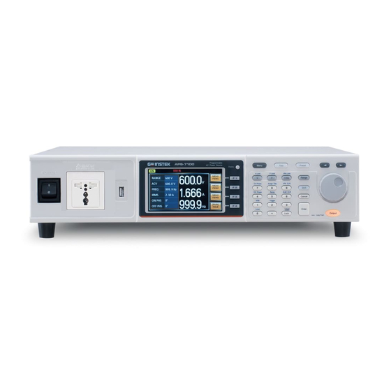
All manuals and user guides at all-guides.com APS-7000 Programming Manual Appearance Front Panel APS-7050, APS-7100 Power Front voltage Display Menu, Test, Arrow keys, switch output socket mode key Preset keys Scroll wheel APS-7050 Programmable AC Power Source Menu Test Preset... - Page 13 All manuals and user guides at all-guides.com GETTING STARTED The USB port is used for data USB A Port transfers and upgrading software. Displays the measured values or LCD Screen menu system. Selects between Standard mode Display Mode Display Select Key and Simple mode.
- Page 14 All manuals and user guides at all-guides.com APS-7000 Programming Manual Switches between the 155V, 310V Range Key Range and 600V ranges (the 600V range is an option). Used to navigate menu items or Scroll Wheel for incrementing/decrementing values one step at a time. Unlock Locks the number pad to prevent Lock Key...
- Page 15 All manuals and user guides at all-guides.com GETTING STARTED Sets the off phase for the output Off Phase (Shift + 4) voltage. Quick settings for Ramp control. RAMP (Shift + 5) Clears alarms. ALM CLR (Shift + 6) Sets the on phase for the output On Phase (Shift + 7) voltage.
- Page 16 Signal Output Trigger Out SYNC OUTPUT INPUT 50 / 60Hz 600Vac MAX. 115 / 230V 3.6kVA MAX. APS-7100 Line voltage input Voltage Input: 115/230±15% VAC; Line Voltage APS-7050 Line frequency: 50Hz/60 Hz Input (Automatically switchable) 115 / 230V 50 / 60Hz...
- Page 17 All manuals and user guides at all-guides.com GETTING STARTED Voltage Input: 115/230±15% APS-7100 VAC ; Line frequency: 50Hz/60 Hz (Automatically OUTPUT INPUT switchable) Output voltage terminal. Rear Voltage Output Socket APS-7050 APS-7100 OUTPUT INPUT OUTPUT SYNC BNC socket. This socket will output...
-
Page 18: Remote Control
All manuals and user guides at all-guides.com APS-7000 Programming Manual EMOTE CONTROL This chapter describes basic configuration of IEEE488.2 based remote control. Interface Configuration ........... 19 Command Syntax ............38 Command List ..............42 Status Register Overview ..........117 Error List ................ 129... -
Page 19: Interface Configuration
All manuals and user guides at all-guides.com REMOTE CONTROL Interface Configuration USB Remote Interface - Optional Type A, host PC side configuration connector Rear panel Type B, slave APS-7000 side connector 1.1/2.0 (full speed/auto speed) Speed CDC (communications device USB Class class) The RS-232/USB interface card (APS-002) must Note... - Page 20 All manuals and user guides at all-guides.com APS-7000 Programming Manual Connection status Speed settings 6. Press Exit[F4] to exit from the rear Exit panel USB settings. RS-232 Remote Interface - Optional The APS-002 RS-232/USB interface card must be installed to remotely control the APS-7000 via the serial port.
- Page 21 All manuals and user guides at all-guides.com REMOTE CONTROL The RS-232/USB interface card (APS-002) must Note first be installed before the USB interface can be used for remote control. Please see the user manual for installation details. 1. Connect the RS-232C cable from Steps the PC to the rear panel RS-232 port.
- Page 22 All manuals and user guides at all-guides.com APS-7000 Programming Manual 6. Press Exit[F4] to exit from the serial Exit port settings. RS-232/USB Remote Control Function Check Invoke a terminal application such as Realterm. Functionality check For both USB and RS-232, set the COM port, baud rate, stop bit, data bit and parity accordingly.
- Page 23 All manuals and user guides at all-guides.com REMOTE CONTROL Serial number : GEXXXXXXX Software version : XX.XX.XXXXXXXX Using Realterm to Establish a Remote Connection Realterm is a terminal program that can be Background used to communicate with a device attached to the serial port of a PC or via an emulated serial port via USB.
- Page 24 All manuals and user guides at all-guides.com APS-7000 Programming Manual for the each connected device. If using USB, the baud rate, stop bit and parity settings can be viewed by right-clicking the connected device and selecting the Properties option. 5. Start Realterm on the PC as an administrator. Click: Start menu>All Programs>RealTerm>realterm Tip: to run as an administrator, you can right...
- Page 25 All manuals and user guides at all-guides.com REMOTE CONTROL 7. Click on the Send tab. In the EOL configuration, check on the +LF check boxes. Enter the query: *idn? Click on Send ASCII. 8. The terminal display will return the following: GWINSTEK,APS-7050, GEXXXXXXX, XX.XX.XXXXXXXX...
- Page 26 All manuals and user guides at all-guides.com APS-7000 Programming Manual (manufacturer, model, serial number, software version) 9. If Realterm fails to connect to the APS-7000, please check all the cables and settings and try again. Configure GPIB Interface - Optional To use GPIB, the optional APS-001 GPIB interface card must first be installed.
- Page 27 All manuals and user guides at all-guides.com REMOTE CONTROL GPIB port configuration 7. Press Exit[F4] to exit from the serial Exit port settings. Maximum 15 devices altogether, 20m cable GPIB constraints length, 2m between each device Unique address assigned to each device ...
- Page 28 All manuals and user guides at all-guides.com APS-7000 Programming Manual Start>All Programs>NI MAX 2. From the Configuration panel access; My System>Devices and Interfaces>GPIB0 3. Press the Scan for Instruments button. 4. In the Connected Instruments panel the APS-7000 should be detected as Instrument 0 with the address the same as that configured on the APS-7000.
- Page 29 All manuals and user guides at all-guides.com REMOTE CONTROL 8. Click on the Input/Output icon. 9. Under the Basic I/O tab, ensure *IDN? is written in the Select or Enter Command text box. 10. Click on the Query button to send the *IDN? query to the instrument.
- Page 30 All manuals and user guides at all-guides.com APS-7000 Programming Manual Configure Ethernet Connection The Ethernet interface can be configured for a number of different applications. Ethernet can be configured for basic remote control or monitoring using a web server or it can be configured as a socket server.
- Page 31 All manuals and user guides at all-guides.com REMOTE CONTROL 6. If DHCP was set to OFF, configure the remaining LAN parameters. IP Address Subnet Mask Gateway DNS Server LAN configuration 7. Press Exit[F4] to exit from the LAN Exit settings.
- Page 32 All manuals and user guides at all-guides.com APS-7000 Programming Manual Web Server Remote Control Function Check Enter the IP address of the power supply (for Functionality check example: http:// XXX.XXX.XXX.XXX) in a web browser after the instrument has been configured for LAN(page 30). The web interface allows you to: View the system and information and the ...
- Page 33 All manuals and user guides at all-guides.com REMOTE CONTROL Socket Server Function Check To test the socket server functionality, National Background Instruments Measurement and Automation Explorer can be used. This program is available on the NI website, www.ni.com., via a search for the VISA Run-time Engine page, or “downloads”...
- Page 34 All manuals and user guides at all-guides.com APS-7000 Programming Manual Resource… 4. Select Manual Entry of Raw Socket from the popup window. 5. Enter the IP address and the port number of the APS-7000. The port number is fixed at 2268. 6.
- Page 35 All manuals and user guides at all-guides.com REMOTE CONTROL 7. Next configure the Alias (name) of the APS- 7000 connection. In this example the Alias is: 8. Click finish. 9. The IP address of the power supply will now appear under Network Devices in the configuration panel.
- Page 36 All manuals and user guides at all-guides.com APS-7000 Programming Manual 11. Click the Configuration Icon. Under the IO Settings tab check Enable Termination Character. The termination character should be set as Line Feed -\n. 12. Click the Input/Output icon. Under the Basic I/O tab, make sure *IDN?\n is entered in the Select or Enter Command drop box.
- Page 37 All manuals and user guides at all-guides.com REMOTE CONTROL...
-
Page 38: Command Syntax
All manuals and user guides at all-guides.com APS-7000 Programming Manual Command Syntax Partial compatibility IEEE488.2 Compatible Partial compatibility Standard SCPI, 1999 SCPI commands follow a tree-like structure, Command Structure organized into nodes. Each level of the command tree is a node. Each keyword in a SCPI command represents each node in the command tree. - Page 39 All manuals and user guides at all-guides.com REMOTE CONTROL A query is a simple or Query compound command followed by a question mark (?). A parameter (data) is returned. meas:curr? Example Two or more commands on Compound the same command line. Compound commands are separated with either a semi- colon (;) or a semi-colon and a...
- Page 40 All manuals and user guides at all-guides.com APS-7000 Programming Manual Commands and queries have two different Command Forms forms, long and short. The command syntax is written with the short form of the command in capitals and the remainder (long form) in lower case.
- Page 41 All manuals and user guides at all-guides.com REMOTE CONTROL Parameters Type Description Example Boolean logic 0, 1 <Boolean> integers 0, 1, 2, 3 <NR1> decimal 0.1, 3.14, 8.5 <NR2> numbers floating point 4.5e-1, 8.25e+1 <NR3> any of NR1, 2, 3 1, 1.5, 4.5e-1 <NRf>...
-
Page 42: Command List
All manuals and user guides at all-guides.com APS-7000 Programming Manual Command List Abort Command :ABORt ................ 47 *CLS ................47 Common Commands *ESE ................48 *ESR ................48 *IDN ................48 *OPC ................49 *RCL ................49 *RST ................49 *SAV ................ - Page 43 All manuals and user guides at all-guides.com REMOTE CONTROL :MEASure[:SCALar]:POWer[:AC]:APParent ..57 :MEASure[:SCALar]:POWer[:AC]:PFACtor ..57 :MEASure[:SCALar]:POWer[:AC]:REACtive ..58 :MEASure[:SCALar]:POWer[:AC][:REAL] .... 58 :MEASure[:SCALar]:VOLTage[:RMS] ....58 :OUTPut:PON ............61 Output Commands :OUTPut:PROTection:CLEar ........61 :OUTPut[:STATe] ............61 :OUTPut[:STATe]:TRIGgered ........62 :STATus:OPERation:CONDition ......63 Status Commands :STATus:OPERation:ENABle ........
- Page 44 All manuals and user guides at all-guides.com APS-7000 Programming Manual :SYSTem:COMMunicate:SERial[:RECeive] :TRANsmit:BAUD ............. 73 :SYSTem:COMMunicate:SERial[:RECeive] :TRANsmit:BITS ............74 :SYSTem:COMMunicate:SERial[:RECeive] :TRANsmit:PARity ............ 74 :SYSTem:COMMunicate:SERial[:RECeive] :TRANsmit:SBITs ............75 :SYSTem:COMMunicate:TCPip:CONTrol ..... 75 :SYSTem:COMMunicate:USB:FRONt:STATe..75 :SYSTem:COMMunicate:USB:REAR:MODE ..76 :SYSTem:COMMunicate:USB:REAR:STATe ..76 :SYSTem:CONFigure:RAMP[:MODE] ....76 :SYSTem:CONFigure:RAMP:VOLTage ....
- Page 45 All manuals and user guides at all-guides.com REMOTE CONTROL :TRIGger:OUTPut:SOURce ........87 Trigger Commands :TRIGger:OUTPut[:IMMediate] ....... 87 :TRIGger:MEMory:SOURce ........87 :TRIGger:MEMory[:IMMediate] ......88 :TRIGger:SEQuence:SELected:EXECute ....88 :TRIGger:SIMulation:SELected:EXECute ....89 :TRIGger[:TRANsient]:SOURce ......89 :TRIGger[:TRANsient][:IMMediate] ....... 89 [:SOURce]:CURRent:LIMit:PEAK:HIGH ....92 Source Commands [:SOURce]:CURRent:LIMit:RMS[:AMPLitude] ..
- Page 46 All manuals and user guides at all-guides.com APS-7000 Programming Manual [:SOURce]:SIMulation:ABNormal:VOLTage..105 [:SOURce]:SIMulation:CSTep ........ 106 [:SOURce]:SIMulation:INITial:CODE....106 [:SOURce]:SIMulation:INITial:FREQuency ..107 [:SOURce]:SIMulation:INITial:PHASe:STARt :ENABle ..............107 [:SOURce]:SIMulation:INITial:PHASe:STARt [:IMMediate] ............107 [:SOURce]:SIMulation:INITial:PHASe:STOP :ENABle ..............108 [:SOURce]:SIMulation:INITial:PHASe:STOP [:IMMediate] ............108 [:SOURce]:SIMulation:INITial:VOLTage ..... 109 [:SOURce]:SIMulation:NORMal<1|2>:CODE ..109 [:SOURce]:SIMulation:NORMal<1|2>...
-
Page 47: Common *Cls
All manuals and user guides at all-guides.com REMOTE CONTROL Abort Command :ABORt ................ 47 :ABORt The ABORt command will cancel any triggered Description actions. Syntax :ABORt IEEE 488.2 Common Commands *CLS ................47 *ESE ................48 *ESR ................48 *IDN ................48 *OPC ................ -
Page 48: Ese
All manuals and user guides at all-guides.com APS-7000 Programming Manual *ESE Query Sets or queries the Standard Event Status Enable Description register. Syntax *ESE <NR1> Query Syntax *ESE? 0~255 Parameter <NR1> Returns the bit sum of the Standard Event Return parameter <NR1> Status Enable register. -
Page 49: Opc
All manuals and user guides at all-guides.com REMOTE CONTROL *OPC Query The *OPC command sets the OPC bit (bit0) of the Description Standard Event Status Register when all current commands have been processed. The *OPC? Query returns 1 when all the outstanding commands have completed. -
Page 50: Sav
All manuals and user guides at all-guides.com APS-7000 Programming Manual *SAV Saves the settings into memory slot M0 ~ M9. Description These memory slots are mapped to the preset settings. Syntax *SAV {<NR1>|MIN|MAX} 0 ~ 9 (as memory M0 ~ M9) Return parameter <NR1>... -
Page 51: Wai
All manuals and user guides at all-guides.com REMOTE CONTROL Returns “0” if there are no errors. Return parameter 0 Returns an error code <NR1> if there is an <NR1> error. *WAI Prevents any other commands or queries from Description being executed until all outstanding commands have completed. -
Page 52: Data/Trace
All manuals and user guides at all-guides.com APS-7000 Programming Manual Data/Trace Commands The DATA and the TRACe node for the following Note commands are functionally equivalent. :DATA|TRACe:SEQuence:CLEar ......52 :DATA|TRACe:SEQuence:RECall ......52 :DATA|TRACe:SEQuence:STORe ......53 :DATA|TRACe:SIMulation:CLEar ......53 :DATA|TRACe:SIMulation:RECall ......53 :DATA|TRACe:SIMulation:STORe ...... -
Page 53: Data|Trace:sequence:store
All manuals and user guides at all-guides.com REMOTE CONTROL Example :DATA:SEQ:REC 1 Loads the data from Seq1. :DATA|TRACe:SEQuence:STORe Saves the sequence data. This command is the Description equivalent to saving a sequence memory in Sequence mode. Syntax :DATA|TRACe:SEQuence:STORe {<NR1>|MINimum|MAXimum} 0~9 (Seq0 ~ Seq9). Parameter <NR1>... -
Page 54: Data|Trace:simulation:store
All manuals and user guides at all-guides.com APS-7000 Programming Manual 0~9 (SIM0 ~ SIM9). Parameter <NR1> Example :DATA:SIM:REC 1 Loads the data from SIM1. :DATA|TRACe:SIMulation:STORe Saves the simulation data. This command is the Description equivalent saving a simulation memory in Simulation mode (SIM0 ~ SIM9). -
Page 55: Initiate[:Immediate]:Name
All manuals and user guides at all-guides.com REMOTE CONTROL Initiate Commands :INITiate[:IMMediate]:NAME ......... 55 :INITiate[:IMMediate][:TRANsient] ....... 55 :INITiate[:IMMediate]:NAME The INITiate command starts the TRANsient, Description OUTPut, MEMory or SDIP (surge/dip) trigger. Syntax :INITiate[:IMMediate]:NAME {TRANsient|OUTPut|MEMory|SDIP} Starts the TRANSient trigger. Parameter TRANsient Starts the OUTput trigger. -
Page 56: Measure[:Scalar]:Current:cfactor
All manuals and user guides at all-guides.com APS-7000 Programming Manual Measure Commands :MEASure[:SCALar]:CURRent:CFACtor ....56 :MEASure[:SCALar]:CURRent:HIGH ....56 :MEASure[:SCALar]:CURRent:PEAK:CLEar ..56 :MEASure[:SCALar]:CURRent:PEAK:HOLD ..57 :MEASure[:SCALar]:CURRent[:RMS] ....57 :MEASure[:SCALar]:FREQuency ......57 :MEASure[:SCALar]:POWer[:AC]:APParent ..57 :MEASure[:SCALar]:POWer[:AC]:PFACtor ..57 :MEASure[:SCALar]:POWer[:AC]:REACtive ..58 :MEASure[:SCALar]:POWer[:AC][:REAL] .... 58 :MEASure[:SCALar]:VOLTage[:RMS] .... -
Page 57: Measure[:Scalar]:Current:peak:hold
All manuals and user guides at all-guides.com REMOTE CONTROL :MEASure[:SCALar]:CURRent:PEAK:HOLD Query Returns the current peak hold value in amps (Ipk). Description Syntax :MEASure[:SCALar]:CURRent:PEAK:HOLD? Returns the peak hold value in amps. Return <NR2> :MEASure[:SCALar]:CURRent[:RMS] Query Returns the output current (Irms). Description Syntax :MEASure[:SCALar]:CURRent[:RMS]? Returns the Irms. -
Page 58: Measure[:Scalar]:Power[:Ac]:Reactive
All manuals and user guides at all-guides.com APS-7000 Programming Manual :MEASure[:SCALar]:POWer[:AC]:REACtive Query Returns the reactive power (VAR). Description Syntax :MEASure[:SCALar]:POWer[:AC]:REACtive? Returns the reactive power in VAR. Return <NR2> :MEASure[:SCALar]:POWer[:AC][:REAL] Query Returns the active power in Watts. Description Syntax :MEASure[:SCALar]:POWer[:AC][:REAL]? Returns the power in W. Return <NR2>... - Page 59 All manuals and user guides at all-guides.com REMOTE CONTROL Memory Commands :MEMory:SAV ............59 :MEMory:RCL ............59 :MEMory:TRIGgered ..........60 :MEMory:SAV Saves the settings into memory slot M0 ~ M9. Description These memory slots are mapped to the preset settings. Equivalent to the *SAV command. Syntax :MEMory:SAV {<NR1>|MINimum|MAXimum} Parameter...
- Page 60 All manuals and user guides at all-guides.com APS-7000 Programming Manual :MEMory:TRIGgered Query Recalls the selected memory (M0 ~ M9) when a Description software trigger is generated. These memory slots are mapped to the preset settings. Syntax :MEMory:TRIGgered {<NR1>|MINimum|MAXimum} Query Syntax :MEMory:TRIGgered? 0 ~ 9 Parameter/...
-
Page 61: Output:pon
All manuals and user guides at all-guides.com REMOTE CONTROL Output Commands :OUTPut:PON ............61 :OUTPut:PROTection:CLEar ........61 :OUTPut[:STATe] ............61 :OUTPut[:STATe]:TRIGgered ........62 :OUTPut:PON Query Sets the output state at power-on. Description Syntax :OUTPut:PON {<bool>|OFF|ON} Return Syntax :OUTPut:PON? Disabled Parameter OFF | 0 Enabled ON | 1... -
Page 62: Output[:State]:Triggered
All manuals and user guides at all-guides.com APS-7000 Programming Manual :OUTPut[:STATe]:TRIGgered Query Turns the output on/off when a software trigger Description has been generated. Syntax :OUTPut[:STATe]:TRIGgered {<bool>|OFF|ON} Query Syntax :OUTPut[:STATe]:TRIGgered? Turns the output off when a software trigger Parameter/ OFF | 0 is generated (*TRG). -
Page 63: Status:operation:condition
All manuals and user guides at all-guides.com REMOTE CONTROL Status Commands For an overview of all the status registers, their associated register contents and the system diagram, please see the status overview on page 117 :STATus:OPERation:CONDition ......63 :STATus:OPERation:ENABle ........64 :STATus:OPERation[:EVENt] ........ -
Page 64: Status:operation:enable
All manuals and user guides at all-guides.com APS-7000 Programming Manual :STATus:OPERation:ENABle Query Sets or queries the bit sum of the Operation Status Description Enable register. Syntax :STATus:OPERation:ENABle <NR1> Query Syntax :STATus:OPERation:ENABle? 0~32767 Parameter <NR1> 0~32767 Return parameter <NR1> :STATus:OPERation[:EVENt] Query Queries the Operation Status Event register and Description clears the contents of the register. -
Page 65: Status:questionable[:Event]
All manuals and user guides at all-guides.com REMOTE CONTROL :STATus:QUEStionable[:EVENt] Query Queries the bit sum of the Questionable Status Description Event register. This query will also clear the contents of the register. Query Syntax :STATus:QUEStionable[:EVENt]? 0~32767 Return parameter <NR1> :STATus:QUEStionable:CONDition Query Queries the status (bit sum) of the Questionable Description... -
Page 66: Status:questionable:ptransition
All manuals and user guides at all-guides.com APS-7000 Programming Manual 0~32767 Parameter <NR1> 0~32767 Return parameter <NR1> :STATus:QUEStionable:PTRansition Query Sets or queries the bit sum of the positive Description transition filter of the Questionable Status register. Syntax :STATus:QUEStionable:PTRansition <NR1> Return Syntax :STATus:QUEStionable:PTRansition? 0~32767 Parameter... -
Page 67: Status:warning:condition
All manuals and user guides at all-guides.com REMOTE CONTROL Summary: The Questionable Status Enable registers, the Operation Status Enable registers and Warning Status registers are both reset to 0. The Questionable Status, Operation Status and Warning Positive Transition filters are all set high (0x7FFF) and the Negative Transition filters are all set low (0x0000). -
Page 68: Status:warning[:Event]
All manuals and user guides at all-guides.com APS-7000 Programming Manual :STATus:WARNing[:EVENt] Query Queries the Warning Status Event register and Description clears the contents of the register. Syntax :STATus:WARNing[:EVENt]? Returns the bit sum of the Warning Status Return <NR1> Event register. :STATus:WARNing:NTRansition Query Sets or queries the bit sum of the negative... - Page 69 All manuals and user guides at all-guides.com REMOTE CONTROL System Function Command :SYSTem:BEEPer:STATe ........... 70 :SYSTem:COMMunicate:GPIB[:SELF]:ADDRess .. 70 :SYSTem:COMMunicate:LAN:DHCP ....70 :SYSTem:COMMunicate:LAN:DNS ....... 71 :SYSTem:COMMunicate:LAN:GATEway ..... 71 :SYSTem:COMMunicate:LAN:IPADdress ..... 71 :SYSTem:COMMunicate:LAN:MAC ...... 72 :SYSTem:COMMunicate:LAN:SMASk ....72 :SYSTem:COMMunicate:RLSTate ......72 :SYSTem:COMMunicate:SERial[:RECeive] :TRANsmit:BAUD .............
-
Page 70: System:beeper:state
All manuals and user guides at all-guides.com APS-7000 Programming Manual :SYSTem:ERRor:ENABle .......... 83 :SYSTem:KLOCk ............84 :SYSTem:REBoot ............84 :SYSTem:WRELease ..........84 :SYSTem:BEEPer:STATe Query Sets or queries the buzzer state on/off. Description Syntax :SYSTem:BEEPer:STATe {<bool>|OFF|ON} Query Syntax :SYSTem:BEEPer:STATe? Turns the buzzer off. Parameter OFF | 0 Turns the buzzer on. -
Page 71: System:communicate:lan:dns
All manuals and user guides at all-guides.com REMOTE CONTROL Syntax :SYSTem:COMMunicate:LAN:DHCP {<bool>|OFF|ON} Query Syntax :SYSTem:COMMunicate:LAN:DHCP? DHCP off Parameter OFF | 0 DHCP on ON | 1 Returns the DHCP status. Return parameter <bool> :SYSTem:COMMunicate:LAN:DNS Query Sets or queries the DNS address. Description The setting will only be valid after the power has Note:... -
Page 72: System:communicate:lan:mac
All manuals and user guides at all-guides.com APS-7000 Programming Manual The setting will only be valid after the power has Note: been cycled. Syntax :SYSTem:COMMunicate:LAN:IPADdress <string> Query Syntax :SYSTem:COMMunicate:LAN:IPADdress? LAN IP address in string format ( “address”) Parameter/Return <string> Applicable ASCII characters: 20H to 7EH Example SYST:COMM:LAN:IPAD “172.16.5.111”... -
Page 73: System:communicate:serial[:Receive] :Transmit:baud
All manuals and user guides at all-guides.com REMOTE CONTROL Syntax :SYSTem:COMMunicate:RLSTate {LOCal|REMote|RWLock} Query Syntax :SYSTem:COMMunicate:RLSTate? All keys are valid. This instrument is Parameter/Return LOCal controlled by the front panel controls. parameter All keys are invalid, except for the [local] key REMote and the ability to turn the output off. -
Page 74: System:communicate:serial[:Receive] :Transmit:bits
All manuals and user guides at all-guides.com APS-7000 Programming Manual :SYSTem:COMMunicate:SERial[:RECeive] :TRANsmit:BITS Query Sets or queries the UART number of data bits. Description The setting will only be valid after the power has Note: been cycled. Syntax :SYSTem:COMMunicate:SERial[:RECeive]:TRANsmit :BITS <NR1> Query Syntax :SYSTem:COMMunicate:SERial[:RECeive]:TRANsmit :BITS? -
Page 75: System:communicate:serial[:Receive] :Transmit:sbits
All manuals and user guides at all-guides.com REMOTE CONTROL Example SYST:COMM:SER:TRAN:PARity? >+0 Indicates that no parity is used for the UART connection. :SYSTem:COMMunicate:SERial[:RECeive] :TRANsmit:SBITs Query Sets or queries the number of stop bits used for the Description UART connection. The setting will only be valid after the power has Note: been cycled. -
Page 76: System:communicate:usb:rear:mode
All manuals and user guides at all-guides.com APS-7000 Programming Manual Query Syntax :SYSTem:COMMunicate:USB:FRONt:STATe? <NR1>Absent Return parameter +0 <NR1>Mass Storage :SYSTem:COMMunicate:USB:REAR:MODE Query Sets or queries the speed of the rear panel USB B Description port. This setting is applied only after the unit is reset. -
Page 77: System:configure:ramp:voltage
All manuals and user guides at all-guides.com REMOTE CONTROL Return parameter <NR1> Ramp mode is disabled. Time mode Voltage mode :SYSTem:CONFigure:RAMP:VOLTage Query Sets or queries the ramp Vup and Vdn parameters. Description Syntax :SYSTem:CONFigure:RAMP:VOLTage[:LEVel][:AMPLitu de] {<NR2>|MINimum|MAXimum,<NR2>|MINimum |MAXimum} Query Syntax :SYSTem:CONFigure:RAMP:VOLTage[:LEVel][:AMPLitu de]? [MINimum|MAXimum] Vup (Vrms). -
Page 78: System:configure[:Mode]
All manuals and user guides at all-guides.com APS-7000 Programming Manual Tup in milliseconds Parameter <NR2> Minimum Tup MINimum Maximum Tup MAXimum Tdn in milliseconds <NR2> Minimum Tdn MINimum Maximum Tdn MAXimum Returns the Tup,Tdn time. Return parameter <NR2>,<NR2> Example :SYST:CONF:RAMP:TIME? >+3.0000,+4.0000 Returns the Tup,Tdn values. -
Page 79: System:configure:sdip:site
All manuals and user guides at all-guides.com REMOTE CONTROL Syntax :SYSTem:CONFigure:SDIP[:MODE] {<NR1>|DISable|MANual|AUTO } Query Syntax :SYSTem:CONFigure:SDIP[:MODE]? Disables surge/dip mode. Parameter 0 | DISable Sets the surge/dip mode to 1 | MANual manual. Sets the surge/dip mode to auto. 2 | AUTO Return parameter <NR1>... -
Page 80: System:configure:sdip:width
All manuals and user guides at all-guides.com APS-7000 Programming Manual ACV level from 0V. Parameter <NR2> Minimum voltage (0V) MINimum Maximum voltage (set voltage range) MAXimum Returns the surge/dip voltage (+NR1). Return parameter <NR1> :SYSTem:CONFigure:SDIP:WIDTh Query Sets or queries the width of the surge/dip site. Description Syntax :SYSTem:CONFigure:SDIP:WIDTh... -
Page 81: System:configure:trigger:input:source
All manuals and user guides at all-guides.com REMOTE CONTROL :SYSTem:CONFigure:TRIGger:INPut :SOURce Query Configures the source for the trigger input. Description Equivalent to the Input Pin>Action settings when Shift + 2[Trigger] is pressed using the front panel controls. Syntax :SYSTem:CONFigure:TRIGger:INPut:SOURce {<NR1>|NONE|OUTPut|SETTing|PRESet} Query Syntax :SYSTem:CONFigure:TRIGger:INPut:SOURce? No source is assigned. -
Page 82: System:configure:trigger:output:source
All manuals and user guides at all-guides.com APS-7000 Programming Manual Return parameter +1 Example :SYST:CONF:TRIG:OUTP:MODE AUTO Sets the rear panel trigger output mode to AUTO. :SYSTem:CONFigure:TRIGger:OUTPut :SOURce Query Configures the source for the trigger output. Description Equivalent to the Output Pin>Source settings when Shift + 2[Trigger] is pressed using the front panel controls. -
Page 83: System:configure:trigger:width
All manuals and user guides at all-guides.com REMOTE CONTROL :SYSTem:CONFigure:TRIGger:WIDTh Query Configures the trigger width of the trigger output. Description Equivalent to the Output Pin>Width settings when Shift + 2[Trigger] is pressed using the front panel controls. Syntax :SYSTem:CONFigure:TRIGger:WIDTh {<NR2>|MINimum|MAXimum} Query Syntax :SYSTem:CONFigure:TRIGger:WIDTh? Width in seconds. -
Page 84: System:klock
All manuals and user guides at all-guides.com APS-7000 Programming Manual :SYSTem:KLOCk Query Enables or disables the front panel key lock. Description Syntax :SYSTem:KLOCk {<bool>|OFF|ON } Query Syntax :SYSTem:KLOCk? Panel keys unlocked Parameter OFF | 0 Panel keys locked ON | 1 Returns the key lock status. - Page 85 All manuals and user guides at all-guides.com REMOTE CONTROL Trigger Commands The triggering commands are divided into trigger input and trigger output commands. The trigger input commands are further divided into Bus, Immediate and External commands. To use the trigger subsystem a trigger source must be selected, the triggering system must then be initiated (immediate trigger only), and finally triggered, either manually or by a system trigger.
- Page 86 All manuals and user guides at all-guides.com APS-7000 Programming Manual Trigger Examples The follow 3 examples show the steps necessary to use the output, transient or memory trigger system: Output Trigger Example: :SYSTem:CONFigure:TRIGger:INPut:MODE MANual :TRIGger:OUTPut:SOURce BUS :OUTPut:STATe:TRIGgered <bool>|OFF|ON :INITiate:IMMediate:NAME OUTPut *TRG Transient Trigger Example: :SYSTem:CONFigure:TRIGger:INPut:MODE MANual...
-
Page 87: Trigger
All manuals and user guides at all-guides.com REMOTE CONTROL :TRIGger:OUTPut:SOURce ........87 :TRIGger:OUTPut[:IMMediate] ....... 87 :TRIGger:MEMory:SOURce ........87 :TRIGger:MEMory[:IMMediate] ......88 :TRIGger:SEQuence:SELected:EXECute ....88 :TRIGger:SIMulation:SELected:EXECute ....89 :TRIGger[:TRANsient]:SOURce ......89 :TRIGger[:TRANsient][:IMMediate] ....... 89 :TRIGger:OUTPut:SOURce Query Sets or queries the trigger source of the output Description trigger. -
Page 88: Trigger:memory[:Immediate]
All manuals and user guides at all-guides.com APS-7000 Programming Manual Syntax :TRIGger:MEMory:SOURce {BUS|IMMediate|EXTernal} Query Syntax :TRIGger:MEMory:SOURce? Memory trigger is generated by the bus. Parameter/ Memory trigger is immediately generated. Return parameter IMMediate The memory trigger is generated when an EXTernal external signal triggers it. -
Page 89: Trigger:simulation:selected:execute
All manuals and user guides at all-guides.com REMOTE CONTROL :TRIGger:SIMulation:SELected:EXECute Sets the control parameters for the selected step for Description the simulation mode. This command can only be executed when the simulation mode is turned on. Syntax :TRIGger:SIMulation:SELected:EXECute {<NR1>|STOP|STARt|HOLD} Go to the step <NR1>. Parameter <NR1>... - Page 90 All manuals and user guides at all-guides.com APS-7000 Programming Manual Syntax :TRIGger[:TRANsient][:IMMediate] Example :TRIG...
- Page 91 All manuals and user guides at all-guides.com REMOTE CONTROL Source Commands [:SOURce]:CURRent:LIMit:PEAK:HIGH ....92 [:SOURce]:CURRent:LIMit:RMS[:AMPLitude] ..93 [:SOURce]:FREQuency:LIMit:HIGH ...... 93 [:SOURce]:FREQuency:TRIGgered ......94 [:SOURce]:FREQuency[:IMMediate] ...... 94 [:SOURce]:FUNCtion:CSINe:CFACtor ....95 [:SOURce]:FUNCtion:CSINe:CLIP ......95 [:SOURce]:FUNCtion:CSINe:SDIP ......96 [:SOURce]:FUNCtion:CSINe:STAircase ....97 [:SOURce]:FUNCtion:CSINe:TYPE ......97 [:SOURce]:FUNCtion[:SHAPe][:IMMediate] ..
-
Page 92: [:Source]:Current:limit:peak:high
All manuals and user guides at all-guides.com APS-7000 Programming Manual [:IMMediate] ............107 [:SOURce]:SIMulation:INITial:PHASe:STOP :ENABle ..............108 [:SOURce]:SIMulation:INITial:PHASe:STOP [:IMMediate] ............108 [:SOURce]:SIMulation:INITial:VOLTage ..... 109 [:SOURce]:SIMulation:NORMal<1|2>:CODE ..109 [:SOURce]:SIMulation:NORMal<1|2> :FREQuency ............. 110 [:SOURce]:SIMulation:NORMal<1|2> :PHASe:STARt:ENABle .......... 110 [:SOURce]:SIMulation:NORMal<1|2> :PHASe:STARt[:IMMediate] ........111 [:SOURce]:SIMulation:NORMal<1|2> :PHASe:STOP:ENABle ........... -
Page 93: [:Source]:Current:limit:rms[:Amplitude]
All manuals and user guides at all-guides.com REMOTE CONTROL Query Syntax [:SOURce]:CURRent:LIMit:PEAK:HIGH? [MINimum|MAXimum] Ipk-Limit in Arms. Parameter <NR2> Minimum settable peak current limit MINimum Maximum settable peak current limit MAXimum Returns the Ipk-Limit value Return parameter <NR2> Example CURR:LIM:PEAK:HIGH? 16.80 Returns the peak current limit as 16.8Arms. -
Page 94: [:Source]:Frequency:triggered
All manuals and user guides at all-guides.com APS-7000 Programming Manual Minimum settable frequency MINimum Maximum settable frequency MAXimum Returns the frequency limit Return parameter <NR2> Example FREQ:LIM:HIGH? >60.50 Returns the frequency limit. [:SOURce]:FREQuency:TRIGgered Query Sets or queries the frequency when triggered. Description Syntax [:SOURce]:FREQuency:TRIGgered... -
Page 95: [:Source]:Function:csine:cfactor
All manuals and user guides at all-guides.com REMOTE CONTROL Example :FREQ 60.00 Sets the frequency of 60Hz. [:SOURce]:FUNCtion:CSINe:CFACtor Query Sets or queries the crest factor setting for the Description waveform. The :SOURce:FUNCtion:CSINe:TYPE command Note: must first be used to set the save slot number (CLP1|2|3) and CFACtor as the waveform type before this command is executed. -
Page 96: [:Source]:Function:csine:sdip
All manuals and user guides at all-guides.com APS-7000 Programming Manual Query Syntax [:SOURce]:FUNCtion:CSINe:CLIP? {CLP1|CLP2|CLP3[,MINimum|MAXimum]} Clip range. 1.0 ~ 10.0 Parameter/Return <NR2> Save slot 1 parameter CLP1 Save slot 2 CLP2 Save slot 3 CLP3 10.0 Example :FUNC:CSIN:CLIP CLP1,2.0 Sets the clip range to 2.0. [:SOURce]:FUNCtion:CSINe:SDIP Query Sets or queries the surge|dip waveform type, site... -
Page 97: [:Source]:Function:csine:staircase
All manuals and user guides at all-guides.com REMOTE CONTROL Example :FUNC:CSIN:SDIP CLP1,100,SQU,50,50 Sets the surge/dip arbitrary waveform parameters as site=square, ACV=50%, site=50%. [:SOURce]:FUNCtion:CSINe:STAircase Query Sets or queries the staircase waveform type and the Description number of “steps” in the waveform. The :SOURce:FUNCtion:CSINe:TYPE command Note: must first be used to set the save slot number... -
Page 98: [:Source]:Function[:Shape][:Immediate]
All manuals and user guides at all-guides.com APS-7000 Programming Manual Syntax [:SOURce]:FUNCtion:CSINe:TYPE {CLP1|CLP2|CLP3,CFACtor|CLIP|SDIP|STAircase| TRIangle} Query Syntax [:SOURce]:FUNCtion:CSINe:TYPE? {CLP1|CLP2|CLP3} Save slot 1 Parameter/Return CLP1 Save slot 2 parameter CLP2 Save slot 3 CLP3 Set the type as a crest factor waveform. CFACtor Set the type as a clipped sine waveform. -
Page 99: [:Source]:Phase:start[:Immediate]
All manuals and user guides at all-guides.com REMOTE CONTROL Example :FUNCtion CLP1 Loads the ARB waveform stored in CLP1. [:SOURce]:PHASe:STARt[:IMMediate] Query Sets or queries the start phase. Description Syntax [:SOURce]:PHASe:STARt[:IMMediate] {<NR2>|MINimum|MAXimum} Query Syntax [:SOURce]:PHASe:STARt[:IMMediate]? [MINimum|MAXimum] Start phase. Parameter/Return <NR2> 0º parameter MINimum 359 º... -
Page 100: [:Source]:Sequence:cparameter
All manuals and user guides at all-guides.com APS-7000 Programming Manual Query Syntax [:SOURce]:READ? Returns each measurement Return parameter <voltage>,<current>, readout as <NR3>. <frequency>,<power>, <SVA>,<ipeak> Example :READ? >+111.9700,+0.0000,+59.9990,+0.0000,+0.0000, +0.0000 [:SOURce]:SEQuence:CPARameter Sets the common parameters for the Sequence Description mode. Please see the user manual for a full description of each parameter. -
Page 101: [:Source]:Sequence:cstep
All manuals and user guides at all-guides.com REMOTE CONTROL <NR2>,<NR2>,<bool>,<NR2>,<bool>,<NR1>,<NR1>, Return parameter <bool>,<NR1>,<NR1>,<NR1>,<bool>,<NR1>,<bool>, <bool> Returns the common parameters in the following order: Step time, on phase, on phase on/off, off phase, off phase on/off, term settings, jump step number, jump on/off, jump count, code, branch1, branch1 on/off, branch2, branch2 on/off, trig out on/off. -
Page 102: [:Source]:Sequence:step
All manuals and user guides at all-guides.com APS-7000 Programming Manual Frequency mode: Constant(1) | <NR1>|CONSt| Keep(2) | Sweep(3) KEEP|SWEep Fixed as sine. Phase angle. Fixed to 120. <NR1> <NR2>,<NR1>|CONSt|KEEP|SWEep,<NR2>,<NR1>| Return parameter CONSt|KEEP|SWEep,<NR2>,<NR1>|CONSt|KEEP|S WEep,SIN,<NR1> Returns the step parameters in the following order: ACV, ACV mode, DCV, DCV mode, frequency, frequency mode, SIN, phase. -
Page 103: [:Source]:Simulation:abnormal:frequency
All manuals and user guides at all-guides.com REMOTE CONTROL External trigger output, HI=1, LO=0. Parameter <NR1> LO, 0 MINimum HI, 1 MAXimum Return parameter +0 Example SIM:ABN:CODE 1 [:SOURce]:SIMulation:ABNormal :FREQuency Query Sets or queries the frequency of the abnormal step Description of the simulation mode. -
Page 104: [:Source]:Simulation:abnormal:phase :Start[:Immediate]
All manuals and user guides at all-guides.com APS-7000 Programming Manual [:SOURce]:SIMulation:ABNormal:PHASe :STARt[:IMMediate] Query Sets or queries the ON Phs parameter of the Description abnormal step for the Simulation mode. Syntax [:SOURce]:SIMulation:ABNormal:PHASe:STARt [:IMMediate] {<NR2>|MINimum|MAXimum} Query Syntax [:SOURce]:SIMulation:ABNormal:PHASe:STARt [:IMMediate]? [MINimum|MAXimum] ON Phs (start phase) <NR2>... -
Page 105: [:Source]:Simulation:abnormal:time
All manuals and user guides at all-guides.com REMOTE CONTROL Sets the off phase of the waveform after the output Note: has been turned off. Syntax [:SOURce]:SIMulation:ABNormal:PHASe:STOP [:IMMediate] {<NR2>|MINimum|MAXimum} Query Syntax [:SOURce]:SIMulation:ABNormal:PHASe:STOP [:IMMediate]? [MINimum|MAXimum] OFF Phs (Stop phase) <NR2> Parameter/Return MINimum parameter MAXimum Example... -
Page 106: [:Source]:Simulation:cstep
All manuals and user guides at all-guides.com APS-7000 Programming Manual Voltage of the abnormal step. <NR2> Parameter/Return Minimum settable voltage MINimum parameter Maximum settable voltage MAXimum Example :SIM:ABN:VOLT MAX Sets the abnormal step voltage to the maximum. [:SOURce]:SIMulation:CSTep Query Returns the currently running step. Description Query Syntax [:SOURce]:SIMulation:CSTep? -
Page 107: [:Source]:Simulation:initial:frequency
All manuals and user guides at all-guides.com REMOTE CONTROL [:SOURce]:SIMulation:INITial:FREQuency Query Sets or queries the frequency of the initial step of Description the simulation mode. Syntax [:SOURce]:SIMulation:INITial:FREQuency {<NR2>|MINimum|MAXimum} Query Syntax [:SOURce]:SIMulation:INITial:FREQuency? [MINimum|MAXimum] Frequency of initial step Parameter/Return <NR2> Minimum frequency parameter MINimum Maximum frequency... -
Page 108: [:Source]:Simulation:initial:phase:stop :Enable
All manuals and user guides at all-guides.com APS-7000 Programming Manual Syntax [:SOURce]:SIMulation:INITial:PHASe:STARt [:IMMediate] {<NR2>|MINimum|MAXimum} Query Syntax [:SOURce]:SIMulation:INITial:PHASe:STARt [:IMMediate]? [MINimum|MAXimum] ON Phs (start phase) <NR2> Parameter/Return MINimum parameter MAXimum Example :SIM:INIT:PHAS:STAR 0 Sets ON Phs to 0. [:SOURce]:SIMulation:INITial:PHASe:STOP :ENABle Query Enables/Disables the OFF Phs parameter of the Description initial step for the Simulation mode. -
Page 109: [:Source]:Simulation:initial:voltage
All manuals and user guides at all-guides.com REMOTE CONTROL OFF Phs (Stop phase) <NR2> Parameter/Return MINimum parameter MAXimum Example :SIM:INIT:PHAS:STOP 0 Sets OFF Phs to 0. [:SOURce]:SIMulation:INITial:VOLTage Query Sets or queries the Vset parameter of the abnormal Description step for the Simulation mode. Syntax [:SOURce]:SIMulation:INITial:VOLTage {<NR2>|MINimum|MAXimum}... -
Page 110: [:Source]:Simulation:normal<1|2> :Frequency
All manuals and user guides at all-guides.com APS-7000 Programming Manual [:SOURce]:SIMulation:NORMal<1|2> :FREQuency Query Sets or queries the frequency of the normal1 or Description normal2 step of the simulation mode. Syntax [:SOURce]:SIMulation:NORMal<1|2>:FREQuency {<NR2>|MINimum|MAXimum} Query Syntax [:SOURce]:SIMulation:NORMal<1|2>:FREQuency? [MINimum|MAXimum] Normal 1 or Normal 2 Parameter/Return <1|2>... -
Page 111: [:Source]:Simulation:normal<1|2> :Phase:start[:Immediate]
All manuals and user guides at all-guides.com REMOTE CONTROL [:SOURce]:SIMulation:NORMal<1|2> :PHASe:STARt[:IMMediate] Query Sets or queries the ON Phs parameter of the Description normal1 or normal2 step for the Simulation mode. Syntax [:SOURce]:SIMulation:NORMal<1|2>:PHASe:STARt[:I MMediate] {<NR2>|MINimum|MAXimum} Query Syntax [:SOURce]:SIMulation:NORMal<1|2>:PHASe:STARt[:I MMediate]? [MINimum|MAXimum] Normal 1 or Normal 2 <1|2>... -
Page 112: [:Source]:Simulation:normal<1|2> :Phase:stop[:Immediate]
All manuals and user guides at all-guides.com APS-7000 Programming Manual [:SOURce]:SIMulation:NORMal<1|2> :PHASe:STOP[:IMMediate] Query Sets or queries the OFF Phs parameter of the Description normal1 or normal2 step for the Simulation mode. Sets the off phase of the waveform after the output Note: has been turned off. -
Page 113: [:Source]:Simulation:normal<1|2> :Voltage
All manuals and user guides at all-guides.com REMOTE CONTROL [:SOURce]:SIMulation:NORMal<1|2> :VOLTage Query Sets or queries the Vset parameter of the normal1 Description or normal2 step for the Simulation mode. Syntax [:SOURce]:SIMulation:NORMal<1|2>:VOLTage {<NR2>|MINimum|MAXimum} Query Syntax [:SOURce]:SIMulation:NORMal<1|2>:VOLTage? [MINimum|MAXimum] Normal 1 or Normal 2 <1|2>... -
Page 114: [:Source]:Simulation:transition<1|2>:Time
All manuals and user guides at all-guides.com APS-7000 Programming Manual Syntax [:SOURce]:SIMulation:REPeat:ENABle {<bool>|OFF|ON} Query Syntax [:SOURce]:SIMulation:REPeat:ENABle? Disabled Parameter/Return OFF | 0 Enabled parameter ON | 1 Example :SIM:REP:ENAB 1 Enables the repeat function. [:SOURce]:SIMulation:TRANsition<1|2> :TIME Query Sets or queries the Time parameter of the transition Description step for the Simulation mode. -
Page 115: [:Source]:Voltage:range
All manuals and user guides at all-guides.com REMOTE CONTROL Example VOLT:LIM:RMS? 600.00 Returns the Vrms limit. [:SOURce]:VOLTage:RANGe Query Sets or queries the voltage range for the Description continuous operation mode. Syntax [:SOURce]:VOLTage:RANGe {<NR1>|R155|R310|R600|AUTO} Query Syntax [:SOURce]:VOLTage:RANGe? [MINimum|MAXimum] Voltage range (155, 310, 600). Parameter <NR1>... -
Page 116: [:Source]:Voltage[:Level][:Immediate] [:Amplitude]
All manuals and user guides at all-guides.com APS-7000 Programming Manual Example :VOLTage:TRIGgered 150.0 Sets the voltage to 150.0 ACV when triggered. [:SOURce]:VOLTage[:LEVel][:IMMediate] [:AMPLitude] Query Sets or queries the RMS voltage for the continuous Description operation mode. Syntax [:SOURce]:VOLTage[:LEVel][:IMMediate][:AMPLitude] {<NR2>(V)|MINimum|MAXimum} Query Syntax [:SOURce]:VOLTage[:LEVel][:IMMediate][:AMPLitude]? [MINimum|MAXimum] Vrms. -
Page 117: Status Register Overview
All manuals and user guides at all-guides.com REMOTE CONTROL Status Register Overview To program the APS power supply effectively, the Status registers need to be understood. This chapter explains in detail how the Status registers are used and how to configure them. Introduction to the Status Registers ...... -
Page 118: The Status Registers
All manuals and user guides at all-guides.com APS-7000 Programming Manual The diagram below shows the structure of the Status registers. The Status Registers Questionable Status Register Condition PTR/NTR Event Enable OC (Over Current) PU (Device error has occurred) OT (Over Temperature) CAL(Calibration data is invalid) OP (Over Power) Always 0... -
Page 119: Questionable Status Register Group
All manuals and user guides at all-guides.com REMOTE CONTROL Questionable Status Register Group The Questionable Status Register Group Overview indicates if any protection modes or limits have been tripped. Questionable Status Register Condition PTR/NTP Event Enable & Not Used & &... - Page 120 All manuals and user guides at all-guides.com APS-7000 Programming Manual CAL (Calibration data is invalid) OP (Over-Power) Over power protection has been tripped Always 0 32768 The Questionable Status Condition Register Condition Register indicates the status of the power supply. If a bit is set in the Condition register, it indicates that the event is true.
-
Page 121: Operation Status Register Group
All manuals and user guides at all-guides.com REMOTE CONTROL Operation Status Register Group The Operation Status Register Group indicates Overview the operating status of the power supply. Operation Status Register Condition PTR/NTP Event Enable & Not Used & Busy Status &... - Page 122 All manuals and user guides at all-guides.com APS-7000 Programming Manual The Operation Status Condition Register Condition indicates the operating status of the power Register supply. If a bit is set in the Condition register, it indicates that the event is true. Reading the condition register does not change the state of the condition register.
-
Page 123: Warning Status Register Group
All manuals and user guides at all-guides.com REMOTE CONTROL Warning Status Register Group The Warning Status Register Group is a Overview secondary protection status register for the supply output. Warning Status Register Condition PTR/NTP Event Enable & Not Used & Output overcurrent (RMS) &... - Page 124 All manuals and user guides at all-guides.com APS-7000 Programming Manual Output OFF after RMS current 2048 limiter is activated RMS current limiter is operating 8192 Always 0 32768 The Warning Status Condition Register Condition indicates the warning status of the power Register supply.
-
Page 125: Standard Event Status Register Group
All manuals and user guides at all-guides.com REMOTE CONTROL Standard Event Status Register Group The Standard Event Status Register Group Overview indicates if any errors have occurred. The bits of the Event register are set by the error event queue. Standard Event Status Register Event Enable... - Page 126 All manuals and user guides at all-guides.com APS-7000 Programming Manual EXE (Execution Error) The EXE bit indicates an execution error due to one of the following: illegal command parameter, parameter out of range, invalid parameter, the command didn’t execute due to an overriding operation condition.
-
Page 127: Register
All manuals and user guides at all-guides.com REMOTE CONTROL Status Byte Register & Service Request Enable Register The Status Byte register consolidates the status Overview events of all the status registers. The Status Byte register can be read with the *STB? query and can be cleared with the *CLS command. - Page 128 All manuals and user guides at all-guides.com APS-7000 Programming Manual MAV (Message Available) This is set when there is data in the Output Queue waiting to be read. (ESB) Event Summary Bit. The ESB is the summary bit for the Standard Event Status Register group.
-
Page 129: Error List
All manuals and user guides at all-guides.com REMOTE CONTROL Error List Command Errors ............. 129 Execution Errors ............133 Device Specific Errors ..........135 Query Errors ............136 Command Errors Overview An <error/event number> in the range [ -199 , - 100 ] indicates that an IEEE 488.2 syntax error has been detected by the instrument’s parser. - Page 130 All manuals and user guides at all-guides.com APS-7000 Programming Manual Error Code Description This is the generic syntax error for devices that -100 Command cannot detect more specific errors. This code Error indicates only that a Command Error as defined in IEEE 488.2,11.5.1.1.4 has occurred. An unrecognized command or data type was -102 Syntax error encountered;...
- Page 131 All manuals and user guides at all-guides.com REMOTE CONTROL The header contains more that twelve -112 Program characters (see IEEE 488.2, 7.6.1.4.1). mnemonic too long The header is syntactically correct, but it is -113 Undefined header undefined for this specific device; for example, *XYZ is not defined for any device.
- Page 132 All manuals and user guides at all-guides.com APS-7000 Programming Manual Either the character data element contains an -141 Invalid invalid character or the particular element character data received is not valid for the header. A legal character data element was encountered -148 Character where prohibited by the device.
- Page 133 All manuals and user guides at all-guides.com REMOTE CONTROL Execution Errors Overview An <error/event number> in the range [ -299 , - 200 ] indicates that an error has been detected by the instrument’s execution control block. The occurrence of any error in this class shall cause the execution error bit (bit 4) in the event status register (IEEE 488.2, section 11.5.1) to be set.
- Page 134 All manuals and user guides at all-guides.com APS-7000 Programming Manual Indicates that a command is not executable -201 Invalid while while the device is in local due to a hard local in local control (see IEEE 488.2, 5.6.1.5); for example, a device with a rotary switch receives a message which would change the switches state, but the device is in local so the message cannot be...
- Page 135 All manuals and user guides at all-guides.com REMOTE CONTROL Indicates that a legal program data element was -222 Data out of parsed but could not be executed because the range interpreted value was outside the legal range as defined by the device (see IEEE 488.2, 11.5.1.1.5.).
- Page 136 All manuals and user guides at all-guides.com APS-7000 Programming Manual or query errors; see the other error definitions in this section. Error Code Description Indicates that some error, termed “system -310 System error error” by the device, has occurred. This code is device-dependent.
- Page 137 All manuals and user guides at all-guides.com REMOTE CONTROL Error Code Description This is the generic query error for devices that -400 Query error cannot detect more specific errors. This code indicates only that a Query Error as defined in IEEE 488.2, 11.5.1.1.7 and 6.3 has occurred.
-
Page 138: Appendix
APS-7000 Default Settings The following default settings are the factory configuration settings for the power supply. For details on how to return to the factory default settings, please see the user manual. Continuous Mode APS-7050 APS-7100 Range 155V 0.00V FREQ 60.00Hz IRMS 4.20A... - Page 139 All manuals and user guides at all-guides.com APPENDIX Sequence Mode APS-7050 APS-7100 Step Time 0.10s Jump To ON, 1 Jump Cnt Branch1 Branch2 Term CONTI Trig Out ON Phs OFF Phs Vset 0.00, CT Fset 50.00 Program Mode APS-7050 APS-7100...
-
Page 140: Index
All manuals and user guides at all-guides.com APS-7000 Programming Manual NDEX Accessories ......... 10 Command list ........ 42 Command syntax ......38 Caution symbol......4 Error list ........129 Cleaning the instrument ..... 6 Ethernet .......... 30 Default settings ......138 GPIB ..........
Need help?
Do you have a question about the APS-7100 and is the answer not in the manual?
Questions and answers