Sign In
Upload
Download
Table of Contents
Contents
Add to my manuals
Delete from my manuals
Share
URL of this page:
HTML Link:
Bookmark this page
Add
Manual will be automatically added to "My Manuals"
Print this page
×
Bookmark added
×
Added to my manuals
Manuals
Brands
Schlage Manuals
IP Access Controllers
RC Pure IP
User manual
Schlage RC Pure IP User Manual
Multi-technology reader controller
Hide thumbs
1
2
Table Of Contents
3
4
5
6
7
8
9
10
11
12
13
14
15
16
17
18
19
20
21
22
23
page
of
23
Go
/
23
Contents
Table of Contents
Bookmarks
Table of Contents
FCC Statement
Table of Contents
Contact Information
Warnings and Cautions
Before You Begin
General Requirements
Reader Controller Specifications
Installation Location Guidelines
Reader Controller Reset Button
Wiring
Powering the Reader Controllers
Door Wiring
Lock Wiring Using Poe
Door Sensor Wiring
Advanced Security Module (ASM) Wiring
Configuring Communications
Reader Controllers to Host Software
Appendix A: Power Options
Poe Power Budget Calculations
Additional Power Options
Dual Power Sources
Appendix B: Additional Wiring Considerations
ASM LED Status Index
Wiring Two Readers to One Lock
Managing Inductive Load Challenges
Poe: Magnetic Lock, ASM and PIR
Appendix C: UL Disclaimers
Advertisement
Quick Links
1
Installation Location Guidelines
2
Wiring
3
Door Wiring
4
Lock Wiring Using Poe
5
Configuring Communications
6
Reader Controllers to Host Software
Download this manual
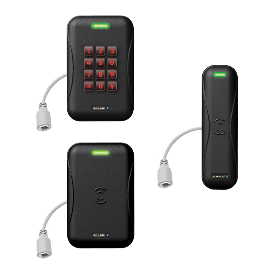
RC Pure IP
TM
multi-technology
reader controller
User guide
Table of
Contents
Previous
Page
Next
Page
1
2
3
4
5
Advertisement
Table of Contents
Need help?
Do you have a question about the RC Pure IP and is the answer not in the manual?
Ask a question
Questions and answers
Related Manuals for Schlage RC Pure IP
IP Access Controllers Schlage Panel Interface Module RS485 Installation & Operating Instructions Manual
Panel interface module-rs485-nexsentry (15 pages)
IP Access Controllers Schlage RC11 User Manual
Multi-technology reader controller (23 pages)
IP Access Controllers Schlage RC15 User Manual
Multi-technology reader controller (23 pages)
IP Access Controllers Schlage RCK15 User Manual
Multi-technology reader controller (23 pages)
IP Access Controllers Schlage MT20 User Manual
Enrollment reader (8 pages)
This manual is also suitable for:
Rc11
Rc15
Rck15
Table of Contents
Print
Rename the bookmark
Delete bookmark?
Delete from my manuals?
Login
Sign In
OR
Sign in with Facebook
Sign in with Google
Upload manual
Upload from disk
Upload from URL


Need help?
Do you have a question about the RC Pure IP and is the answer not in the manual?
Questions and answers