Sign In
Upload
Manuals
Brands
Nivus Manuals
Transmitter
NivuFlow 650
Nivus NivuFlow 650 Manuals
Manuals and User Guides for Nivus NivuFlow 650. We have
1
Nivus NivuFlow 650 manual available for free PDF download: Instruction Manual
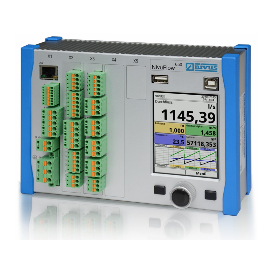
Nivus NivuFlow 650 Instruction Manual (173 pages)
Flow Measurement Transmitter
Brand:
Nivus
| Category:
Transmitter
| Size: 6.84 MB
Table of Contents
Copyrights and Property Rights
3
Document Modifications
4
Table of Contents
5
General
12
Signs and Definitions Used
12
Abbreviations Used
13
1 About this Manual
12
Applicable Documentation
12
2 Connections and Operating Elements
13
Power Supply
13
Nivuflow Operating Elements
14
Tasks of Control Elements
14
Interfaces
15
Safety Instructions
16
3 General: Used Symbols and Signal Words
16
Valuation of the Accident Level
16
4 Safeguards and Precautions
17
Warning Notices on the Product (Option)
17
5 Warranty
18
6 Liability Disclaimer
18
7 Use in Accordance with the Requirements
19
8 User's Responsibilities
19
9 Personnel Requirements
20
Delivery, Storage and Transport
21
10 Delivery
21
11 Reception Inspection
21
12 Storage
21
13 Transport
21
14 Return
21
Product Specification
22
15 Product Construction and Overview
22
Dimensions of Enclosure
23
Connectable Sensors
24
Device Identification
24
16 Specifications
25
17 Configuration
26
Device Types
26
Additionally Bookable Function Licences
27
Functional Description
28
18 Operating Ranges
28
Flow Velocity Detection
29
19 Functional Principle
29
Flow Calculation
30
Installation and Connection
31
20 General Installation Instructions
31
Avoidance of Electrostatic Discharge (ESD)
31
Installation and Mounting Versions
31
Choosing the Installation Place
32
Transmitter Fastening on DIN Rail in Control Cabinets
32
Field Enclosure Fastening and Preparing Electric Installation
33
21 Electrical Installation
35
Wiring to the Terminal Blocks
35
Plans of Terminal Connections
37
Power Supply DC
42
Switching on Voltage Supply
42
Power Supply AC
43
22 Installation and Connection of Sensors
44
Relays
44
Sensor Installation Principles
44
Installation of Clamp-On Sensors
45
Installation of Wet Sensors
45
Path Arrangements
45
Cable and Cable Length for Connecting the Sensors
46
Sensor Connection 1-Path Measurement / 2-Path Measurement
46
Sensor Connection to Nivuflow
46
Connection To/Via Extension Module NFE
47
23 Controller Operation (Function Additionally Bookable as Licence)
47
General
47
Control Section Setup
49
Control Algorithm
50
Regulator Mode Wiring Diagram
50
24 Overvoltage Protection Measures
51
Overvoltage Protection for Power Supply
52
Overvoltage Protection for Communication Interfaces
53
Overvoltage Protection for Ma-Inputs/Outputs
53
Basic Protection - Equipotential Bonding Cable
54
Extended Protection - Overvoltage Protection "Sonicpro T
54
Overvoltage Protection for (Transit Time) Sensor Connectors
54
Operation Start-Up
58
25 Notes to Users
58
Display Overview
59
26 Operation Basics
59
Using the Control Elements
59
Use/Entry Using the Letter Block
60
Revision of Parameters
61
Use/Entry Using the Numeric Keypad
61
27 Information for the Measurement with Wet Sensors
62
Menus
62
Start-Up Examples
64
28 Example 1: Measurement in Open Channels
64
In General
64
Set Parameters of a System with Multiple Crossed Paths
64
Simple Parameter Setting
64
Extended Parameter Setting
68
29 Example 2: Measurement in Open Waters
69
In General
69
Setting Parameters of a Multi-Path System in >Channel
70
Setting Parameters
74
30 General Programming
74
Change Password
74
Modification Of Parameters: Exit Menus
74
Save Parameters
74
Application Menu / MP1 / MP2 / Combi
75
Main Menu
75
Overview: Functions Top Menu Level
75
31 Parameter Functions
75
Data Menu
76
System Menu
77
Communication Menu
78
Display Menu
78
32 Application / MP1 / MP2 / Combi Parameter Menu
79
Connections Menu
79
Setting Parameters in Measurement Place Menu
79
Active
80
Name of Measurement Place
80
Medium
81
Number of Paths
81
Path Arrangement
81
Sonicpro T
81
Channel Profiles
82
Medium Temperature
82
Channel Profile Offset
87
Preview
87
Sludge Level
87
Velocity Evaluation
87
V-Determination Low Levels
88
Damping
90
Low-Flow Suppression
90
Setting Parameters in Measurement Place Combi Menu
91
Stability
91
H-Sensor Types
92
Setting Parameters in H-Sensors Menu
92
Overlapped
93
Deviation (Abs.)
94
Active
95
Fallback
95
Sensor Types
95
Setting Parameters in V-Paths Menu
95
Sensor Mounting Position
96
Coverage
97
V-Minimum and V-Maximum
97
V-Path Error
97
Setting Parameters in Inputs and Outputs (Analog and Digital) Menu
98
Analog Inputs
98
Analog Outputs
99
Digital Inputs
102
Digital Outputs
103
Setting Parameters in Q-Control Menu (Function Bookable as Extra Licence)
105
Setting Parameters in Diagnostics Menu
106
33 Data Parameter Menu
107
Weighting
97
Trend
107
Day Totals
110
Total
110
USB Stick
112
Data Storage
116
Operating Hours
116
Information
117
Region Settings
117
34 System Parameter Menu
117
Date Format
118
Operation) Language
118
Units
118
Data Units
119
Time/Date
120
Error Messages
121
Service
121
Change (System) Password
122
Service Level
122
Feature Unlock
123
Reboot
123
Restart Measurement
123
Parameter Reset
124
Update H-Sensor
124
Update Nivuflow
124
35 Communication Parameter Menu
125
Tcp/Ip
125
Web Server
125
HART (Extra Function Bookable as Licence)
126
Modbus
127
36 Display Parameter Menu
129
37 Connections Parameter Menu
131
Main Display
132
38 General Overview
132
Display Flow in Measurement Places 1 and 2
134
Display Level in Measurement Places 1 and 2
134
Display Velocity in Measurement Places 1 and 2
135
Display Sum in Measurement Places 1 and 2
136
Display Temperature in Measurement Places 1 and 2
136
Display Flow in Measurement Place Combi
137
Display Trend/Hydrograph in Measurement Places 1 and 2
137
Display Measurement Place 1/2 in Measurement Place Combi
138
Display Total in Measurement Place Combi
139
Diagnostics
140
39 Diagnostics Menu Principles
140
40 Diagnostics H-Sensors
141
41 Diagnostics V-Paths
142
42 Inputs and Outputs (Analog and Digital)
143
Analog Inputs
144
Analog Outputs
144
Digital Inputs
146
Digital Outputs
146
43 Control (Extra Function Bookable as Licence)
148
44 Signal Analysis
149
45 Simulation
154
Error Messages
156
46 Error Message Indicated, Cause of Failure and Troubleshooting
156
Maintenance and Cleaning
166
47 Maintenance
166
Maintenance Interval
166
Customer Service Information
166
48 Cleaning
167
Transmitter
167
Sensors
167
49 Dismantling/Disposal
167
50 Installation of Spare Parts and Parts Subject to Wear and Tear
168
51 Accessories
168
Advertisement
Advertisement
Related Products
Nivus NivuFlow Mobile 600
Nivus NivuFlow Mobile 600 Ex
Nivus NivuFlow 750
Nivus NivuFlow Mobile 550
Nivus NivuFlow Mobile 550 Ex
Nivus NivuFlow Mobile 750 Ex
Nivus NivuFlow Stick
Nivus OCM F
Nivus Categories
Measuring Instruments
Transmitter
Surge Protector
Accessories
Data Loggers
More Nivus Manuals
Login
Sign In
OR
Sign in with Facebook
Sign in with Google
Upload manual
Upload from disk
Upload from URL