Panasonic GM1 Series Reference Manual
Motion controller
Hide thumbs
Also See for GM1 Series:
- User manual (650 pages) ,
- Reference manual (166 pages) ,
- Reference manual (126 pages)
Table of Contents
Advertisement
Quick Links
Advertisement
Table of Contents

Related Manuals for Panasonic GM1 Series


Summary of Contents for Panasonic GM1 Series
- Page 1 Motion Controller GM1 Series Reference Manual Hardware WUME-GM1H-01 2021.2...
- Page 2 (MEMO) WUME-GM1H-01...
- Page 3 Types of Manual ● There are different types of manuals for the GM1 series. Refer to the appropriate manual according to your need. ● These manuals can be downloaded from our website: https://industrial.panasonic.com/ac/e/...
- Page 4 (MEMO) WUME-GM1H-01...
-
Page 5: Table Of Contents
3.2.1 Names and Functions of Components of the GM1 Digital I/O Unit . 3-8 3.2.2 Terminal Layout Diagram ..............3-9 4 Installation .....................4-1 4.1 Installation of the GM1 Series.............4-2 4.1.1 Installation Environment and Space ..........4-2 4.1.2 Unit Installation Procedure ............... 4-4 4.1.3 Removing the Unit ................ - Page 6 5.4.2 Wiring the Discrete-wire Connector ..........5-11 5.5 Safety Measures .................5-14 5.5.1 General Safety Measures ..............5-14 5.5.2 Momentary Power Failure ..............5-14 5.5.3 Watchdog Timer ................5-14 6 Checking Wiring..................6-1 6.1 Safety Circuit Design ................6-2 6.2 Items to Check during Wiring..............6-3 6.3 Power ON Operation................6-4 6.4 Power OFF Operation.................6-5 7 Items to Check before Operation ............7-1...
- Page 7 12.2.1 High-speed Counter Input Specifications of the GM1 Controller ... 12-4 12.2.2 Input Specifications of the GM1 Controller ........12-4 12.2.3 Output Specifications (Sink Type) of the GM1 Controller ..... 12-5 12.3 Specifications of Expansion Units.............12-7 12.3.1 Input Specifications of the 64-point Digital Input Unit ....12-7 12.3.2 Output Specifications of the 64-point Digital Output Unit (Sink Type) ....................
- Page 8 (MEMO) viii WUME-GM1H-01...
-
Page 9: Before Using This Product
1 Before Using This Product 1.1 Safety Precautions................1-2 1.2 Handling Precautions................1-3 WUME-GM1H-01... -
Page 10: Safety Precautions
● Do not perform work (such as connection or removal) with the power turned on. Doing so may result in electrical shock. ● If this product is used in any way that is not specified by Panasonic, its protection function may be impaired. -
Page 11: Handling Precautions
1.2 Handling Precautions 1.2 Handling Precautions ■ In this manual, the following symbols are used to indicate safety information that must be observed. Indicates an action that is prohibited or a matter that requires caution. Indicates an action that must be taken. Indicates supplemental information. - Page 12 (MEMO) WUME-GM1H-01...
-
Page 13: Overview (System Configuration)
2 Overview (System Configuration) 2.1 Basic System Configuration..............2-2 2.1.1 Outline of the GM1 System .............. 2-2 2.1.2 Unit Types ..................2-2 2.1.3 Restrictions on the Number of Expansion Units ......2-3 2.2 Restrictions on the GM1 Controller and Servo Amplifiers....2-4 2.2.1 Restrictions on the Combination of the GM1 Controller and Servo Amplifiers .................. -
Page 14: Basic System Configuration
2.1 Basic System Configuration 2.1 Basic System Configuration 2.1.1 Outline of the GM1 System ■ Network control A MINAS series servomotor network system can be easily configured using the RTEX network dedicated to motion control. ■ System configuration including virtual axes It is possible to create a system that consists of up to 20 axes including a maximum of 16 real axes and a maximum of 20 virtual axes. -
Page 15: Restrictions On The Number Of Expansion Units
2.1 Basic System Configuration ■ Expansion units Digital I/O unit Type Function Model number Digital input (64 points) 24 V DC, 64 input points AGM1X64D2 Output (64 points) Digital output (64 points) (sink type) AGM1Y64T Transistor NPN type 24 V DC, 32 input points Digital I/O (64 points) (sink type) 32 output points AGM1XY64D2T... -
Page 16: Restrictions On The Gm1 Controller And Servo Amplifiers
2.2 Restrictions on the GM1 Controller and Servo Amplifiers 2.2 Restrictions on the GM1 Controller and Servo Amplifiers 2.2.1 Restrictions on the Combination of the GM1 Controller and Servo Amplifiers As for the combination of the GM1 Controller and each MINAS series, confirm the following restrictions. - Page 17 2.2 Restrictions on the GM1 Controller and Servo Amplifiers Standard factory Name Description default setting RTEX function Use setting value “1 (32-byte mode)”. Pr7.22 extended setup (Note 2) (Mandatory) Use setting value “18”. (Mandatory) This parameter sets each function in bits. bit 0: Allow parameter values to be written via RTEX communication 0: Allow, 1: Disallow...
- Page 18 2.2 Restrictions on the GM1 Controller and Servo Amplifiers Standard factory Name Description default setting Bit 15: Select extended RTEX status from In_Progress / AC_OFF / Pr7.112 settings 0: Follow the setting of Pr7.23 bit 8 (In_Progress / AC_OFF) 1: Follow the setting of Pr7.112. Use setting value “1 (command unit/s)”.
-
Page 19: Programming Tools
2.3 Programming Tools 2.3 Programming Tools 2.3.1 Software Usage Environment and Applicable Cables Programming software Applicable Applicable Product name Product No. Remarks version language Japanese / GM Programmer Ver.1.0 AGMSMP English / Chinese (Note 1) When the GM Programmer is installed, MINAS setup support software ""PANATERM Lite for GM"" is installed at the same time. - Page 20 (MEMO) WUME-GM1H-01...
-
Page 21: Names And Functions Of Components
3 Names and Functions of Components 3.1 Names and Functions of Components of the GM1 Controller ....3-2 3.1.1 Names and Functions of Components..........3-2 3.1.2 Terminal Layout Diagram ..............3-4 3.2 Expansion Units ..................3-8 3.2.1 Names and Functions of Components of the GM1 Digital I/O Unit . 3-8 3.2.2 Terminal Layout Diagram .............. -
Page 22: Names And Functions Of Components Of The Gm1 Controller
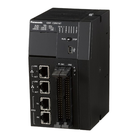
3.1 Names and Functions of Components of the GM1 Controller 3.1 Names and Functions of Components of the GM1 Controller 3.1.1 Names and Functions of Components Name Function LEDs indicate the GM1 Controller state. Operation monitor LEDs Refer to "Names and functions of operation monitor LEDs". - Page 23 3.1 Names and Functions of Components of the GM1 Controller Name Function Used to select either the input state (X) or the output state (Y) of Display selector switch operation monitor LEDs Used to connect to a personal computer that uses a tool software. USB port (miniB type) Used to change the mode to RUN or STOP.
-
Page 24: Terminal Layout Diagram
3.1 Names and Functions of Components of the GM1 Controller Name LED color Function Green Indicates the operating state of the application. RUN (Lit) and STOP (Unlit): The application is in the operating state. RUN (Unlit) and STOP (Lit): The application is in the stopped state. STOP Green RUN (Unlit) and STOP (Unlit): No application exists. - Page 25 3.1 Names and Functions of Components of the GM1 Controller High-speed counter input terminal arrangement Pin No. Circuit Signal name Input A: 24 V DC (12 to 24 V DC) Input A: 5 V DC (3.5 to 5 V DC) Input A: COM Input A: COM Input B: 24 V DC (12 to 24 V DC)
- Page 26 3.1 Names and Functions of Components of the GM1 Controller Terminal layout Pin No. General- Signal name purpose I/O Column C High-speed counter ch0 control 0 signal High-speed counter ch0 control 1 signal High-speed counter ch1 control 0 signal High-speed counter ch1 control 1 signal (Note 1) (Note 1) High-speed counter ch0 external output 0 signal...
- Page 27 3.1 Names and Functions of Components of the GM1 Controller Pin No. General- Signal name purpose I/O Column C (Note 1) (Note 1) (Note 2) (Note 3) (Note 1) The COM terminals (4 places) of the general-purpose input are connected within the unit. (Note 2) The positive terminals (2 places) of the general-purpose output are connected within the unit.
-
Page 28: Expansion Units
3.2 Expansion Units 3.2 Expansion Units 3.2.1 Names and Functions of Components of the GM1 Digital I/O Unit Name Function Unit connector This is a connector to which each expansion unit is connected. Operation monitor LEDs These LEDs indicate the status of expansion units. This is a switch used to select I/O information to be displayed on Display selector switch LEDs. -
Page 29: Terminal Layout Diagram
3.2 Expansion Units Name LED color Function Unlit: Normal Indicates the ON / OFF state of the expansion unit depending on the state of the display selector switch. ● 64-point digital input unit • Display selector switch CN1 Lit: Each terminal of the X0-1F is ON. Unlit: Each terminal of the X0-1F is OFF. - Page 30 3.2 Expansion Units Terminal layout diagram of the 64-point digital output unit (sink type) Terminal layout diagram of the 64-point digital I/O unit (sink type) 3-10 WUME-GM1H-01...
-
Page 31: Installation
4 Installation 4.1 Installation of the GM1 Series.............4-2 4.1.1 Installation Environment and Space ..........4-2 4.1.2 Unit Installation Procedure ............... 4-4 4.1.3 Removing the Unit ................4-5 4.1.4 Attaching to DIN Rail................ 4-6 4.1.5 Removing from DIN Rail ..............4-7... -
Page 32: Installation Of The Gm1 Series
● Always rid yourself of any static electricity before handling this product. ● Do not connect a unit other than our GM1 series to the side connector on the unit. ● Use copper wires with a temperature rating of 80°C. - Page 33 ● Secure a clearance of at least 170 mm from the mounting surface of the GM1 Series for connecting tool software cables. WUME-GM1H-01...
-
Page 34: Unit Installation Procedure
4.1 Installation of the GM1 Series 4.1.2 Unit Installation Procedure ● Install the expansion unit between the GM1 Controller and the end unit. ● Make sure to connect an end unit. ● Make sure to turn OFF the power supply before installing the unit. -
Page 35: Removing The Unit
4.1 Installation of the GM1 Series Lower the expansion hooks to lock the units in place. 4.1.3 Removing the Unit Raise expansion hooks on the sides of the unit with a screwdriver to release them. WUME-GM1H-01... -
Page 36: Attaching To Din Rail
4.1 Installation of the GM1 Series Slide the unit sideways to remove it. 4.1.4 Attaching to DIN Rail Using a screwdriver, push down the DIN rail attachment lever on the back of each unit. Fit the top of the unit attachment part into the DIN rail. -
Page 37: Removing From Din Rail
4.1 Installation of the GM1 Series Push up the DIN rail attachment lever on the back of the unit until it "clicks" to lock. 4.1.5 Removing from DIN Rail Using a screwdriver, push down the DIN rail attachment lever on the back of each unit. - Page 38 4.1 Installation of the GM1 Series Pull the bottom of the unit toward you. While holding up the unit, remove it from the DIN rail. WUME-GM1H-01...
-
Page 39: Wiring
5 Wiring 5.1 Wiring the Power Supply..............5-2 5.1.1 Common Precautions ..............5-2 5.1.2 Power Supply for the GM1 Controller ..........5-3 5.1.3 Grounding ..................5-3 5.2 Wiring of Network................5-5 5.3 Wiring of Input and Output ..............5-6 5.3.1 Precautions Common to Input and Output........5-6 5.3.2 Input Wiring .................. -
Page 40: Wiring The Power Supply
5.1 Wiring the Power Supply 5.1 Wiring the Power Supply 5.1.1 Common Precautions ■ Selection of a power supply ● Use a low noise power supply. ● The inherent noise resistance is sufficient for the noise superimposed on the power wires, however, the noise can be attenuated further by using the isolation transformer / insulated power supply. -
Page 41: Power Supply For The Gm1 Controller
5.1 Wiring the Power Supply 5.1.2 Power Supply for the GM1 Controller ■ Wiring the Power Supply Unit Wiring diagram GM1 Controller ■ Selection of a power supply ● To protect the system against erroneous voltage from the power supply line, use an insulated power supply with an internal protective circuit (power supply with reinforced insulation or double insulation). - Page 42 5.1 Wiring the Power Supply ● Conversely, depending on your environment, grounding may cause a problem. As for the GM1 Controller, since its power supply line is connected to the function earth through a high-voltage capacitor, it is no problem. ●...
-
Page 43: Wiring Of Network
● Turn OFF the power to the system before wiring cables. ● The Ethernet hub cannot be used. ● For detailed information of cable specifications and precautions, refer to the data "RTEX Cable" listed on the web page. https://industrial.panasonic.com/ac/e/dl_center/manual/ WUME-GM1H-01... -
Page 44: Wiring Of Input And Output
5.3 Wiring of Input and Output 5.3 Wiring of Input and Output 5.3.1 Precautions Common to Input and Output ■ Wiring arrangement Arrange the wiring so that the input and output wiring are separated, and these wirings are separated from the power wiring, as much as possible. Do not route them through the same duct or tie them in a bundle. -
Page 45: High-Speed Counter Input Wiring
5.3 Wiring of Input and Output Two-wire output type ■ Precaution when using LED-equipped reed switch When a LED is connected in series to an input contact such as LED-equipped reed switch, make sure that the voltage applied to the GM1 input terminal is greater than the ON voltage. In particular, take care when connecting a number of switches in series. - Page 46 5.3 Wiring of Input and Output ■ For line driver of encoder input ■ For transistor open collector type of encoder input WUME-GM1H-01...
-
Page 47: Output Wiring
5.3 Wiring of Input and Output ■ For sensor input 5.3.4 Output Wiring ■ Protective circuit for inductive loads With an inductive load, a protective circuit should be installed in parallel with the load. ■ Precautions when using capacitive loads When connecting loads with large in-rush currents, to minimize their effect, connect a protection circuit as shown below. -
Page 48: Connection Using The Discrete-Wire Connector
This is a connector that allows loose wires to be connected without removing the wire’s insulation. Use a special tool for wire connection. Discrete-wire connector (40P) ■ AFP2801 Discrete-wire Connector (Purchase separately) Manufacturer Composition of parts Quantity (2 sets) Panasonic Housing 1 pc. (AFP2801) (40P) Semi-cover 2 pcs. -
Page 49: Wiring The Discrete-Wire Connector
5.4 Connection Using the Discrete-wire Connector 5.4.2 Wiring the Discrete-wire Connector ● When performing wiring work, refer to the instruction manual of the crimping tool in order to prevent faulty wiring. Bend and break the contact, and set it in the crimping tool. Insert the wire without removing its insulation until it stops, and lightly grip the crimping tool. - Page 50 5.4 Connection Using the Discrete-wire Connector When all the wires have been inserted, fit the semi-cover into place. 5-12 WUME-GM1H-01...
- Page 51 5.4 Connection Using the Discrete-wire Connector ● If there is a wiring mistake or the wire is incorrectly press-fit, use the crimping tool to remove the contact. Set the pin of the crimping tool at the position indicated by an arrow. Hold the housing with fingers and pull the wire.
-
Page 52: Safety Measures
5.5 Safety Measures 5.5 Safety Measures 5.5.1 General Safety Measures ■ Precautions regarding system design ● In the system where the GM1 is used, malfunction may occur for the following reasons: • Power on timing differences between the GM1 system and I/O devices or power devices. •... - Page 53 5.5 Safety Measures ● When the watchdog timer is activated, the "Alarm" LED on the front of the Controller is lit. When this occurs, all outputs to the output units are turned OFF and the unit is put in halted state.
- Page 54 (MEMO) 5-16 WUME-GM1H-01...
-
Page 55: Checking Wiring
6 Checking Wiring 6.1 Safety Circuit Design ................6-2 6.2 Items to Check during Wiring..............6-3 6.3 Power ON Operation................6-4 6.4 Power OFF Operation.................6-5 WUME-GM1H-01... -
Page 56: Safety Circuit Design
6.1 Safety Circuit Design 6.1 Safety Circuit Design ■ Example of a safety circuit Be sure to create a safety circuit when using this product. Installation of over limit switches ● Install over limit switches as shown above. ● Connect them to the CW and CCW over-travel inhibit inputs of the parallel I/O connector of the servo amplifier. -
Page 57: Items To Check During Wiring
6.2 Items to Check during Wiring 6.2 Items to Check during Wiring ■ System configuration example (1) Checking connections of each device Check to make sure that each device has been connected as indicated by the design. (2) Checking the installation of the external safety circuit Check to make sure the safety circuit (wiring and installation of over limit switch) based on the external circuit has been installed properly. -
Page 58: Power On Operation
6.3 Power ON Operation 6.3 Power ON Operation When turning ON the power supply to the system incorporating the GM1 Controller, turn ON the power supply in the following order. ● Consider the nature and statuses of any external devices connected to the system, and take sufficient care so that turning ON the power supply will not initiate unexpected movements. -
Page 59: Power Off Operation
6.4 Power OFF Operation 6.4 Power OFF Operation Check to make sure the rotation of the motor has stopped, and then turn OFF the power supply to the GM1 Controller. Turn OFF the power supply to the servo amplifier. Turn OFF the power supplies to the I/O devices connected to the GM1 Controller. WUME-GM1H-01... - Page 60 (MEMO) WUME-GM1H-01...
-
Page 61: Items To Check Before Operation
7 Items to Check before Operation 7.1 System Configuration................7-2 7.1.1 Setting an Address for Each Servo Amplifier ........7-2 7.1.2 Power On and Checking Network Connection Establishment ..7-2 7.1.3 Checking Input Signals ..............7-3 7.1.4 Checking Rotating and Moving Directions and Moving Distance ..7-4 7.1.5 Positioning Parameter Setting ............ -
Page 62: System Configuration
7.1 System Configuration 7.1 System Configuration 7.1.1 Setting an Address for Each Servo Amplifier The table below shows the correspondence between the axis numbers of the GM1 Controller and the station numbers on the rotary switch of the servo amplifier. The order of connections on the network is unrelated to axis numbers. -
Page 63: Checking Input Signals
7.1 System Configuration Turn ON the power supply to the GM1 Controller. After turning on the power supplies, check if the operation monitor LEDs of the GM1 Controller are in the following states. STATUS: Lit LINK: Lit ● If the "STATUS" LED is flashing, the network is not established. ●... -
Page 64: Checking Rotating And Moving Directions And Moving Distance
7.1 System Configuration 7.1.4 Checking Rotating and Moving Directions and Moving Distance Check whether the rotating and moving directions of the motor and the moving distance are correct. The operations can be easily confirmed using the commissioning function of the GM Programmer without user programs. - Page 65 7.1 System Configuration Multi-axis control setting Add CNC Setting> CNC Program on the navigator and make the settings. For details on the positioning parameter setting , refer to the GM1 Controller RTEX User’s Manual (Operation Edition). WUME-GM1H-01...
- Page 66 (MEMO) WUME-GM1H-01...
-
Page 67: Using The Sd (Sdhc) Memory Card
8 Using the SD (SDHC) Memory Card 8.1 Preparation of the SD (SDHC) Memory Card ........8-2 8.2 Inserting the SD (SDHC) Memory Card..........8-3 WUME-GM1H-01... -
Page 68: Preparation Of The Sd (Sdhc) Memory Card
If the SD (SDHC) memory card needs to be formatted, download the formatting software for SD (SDHC) memory cards from the following website. "Panasonic website:" https://panasonic.jp/support/sd_w/download/index.html ● The SD (SDHC) memory card file system formatted by PC’s standard formatting software does not satisfy the SD (SDHC) memory card specifications. -
Page 69: Inserting The Sd (Sdhc) Memory Card
8.2 Inserting the SD (SDHC) Memory Card 8.2 Inserting the SD (SDHC) Memory Card ● Do not apply an excessive force to the card cover when opening or closing it or when the cover is left open. Otherwise, the cover attachment part will be deformed to cause malfunction in the cover switch mounted inside the product. - Page 70 8.2 Inserting the SD (SDHC) Memory Card When removing the SD (SDHC) memory card, make sure that the "SD" LED on the GM1 Controller is not lit. WUME-GM1H-01...
-
Page 71: Device Reset
9 Device Reset 9.1 Device Reset by GM1 Controller Operation........9-2 WUME-GM1H-01... -
Page 72: Device Reset By Gm1 Controller Operation
9.1 Device Reset by GM1 Controller Operation 9.1 Device Reset by GM1 Controller Operation Controller information on the GM Programmer can be deleted (initialized) from the GM1 Controller. Confirm that the power supply is turned OFF, set the mode selector switch to "STOP", and set SW2 (reset bit) of the DIP switch to "ON". -
Page 73: Troubleshooting
10 Troubleshooting 10.1 Self-diagnostic Function..............10-2 10.2 Operation Status at the Time of Error ..........10-3 10.3 What to Do If an Error Occurs............10-4 10.3.1 ERROR LED Flashes on the Control Unit ........10-4 10.3.2 ALARM LED Lights on the Control Unit ......... 10-4 10.3.3 POWER LED Does not Light on the Control Unit ...... -
Page 74: Self-Diagnostic Function
10.1 Self-diagnostic Function 10.1 Self-diagnostic Function The GM1 Controller has a self-diagnostic function which identifies errors and stops operation if necessary. Indications concerning self-diagnosis are as follows. ■ LEDs related to self-diagnostic errors ●: Lit, ▲: Flashing, ○: Unlit, -: Indefinite (Lit or unlit) LED display Operation Description... -
Page 75: Operation Status At The Time Of Error
10.2 Operation Status at the Time of Error 10.2 Operation Status at the Time of Error ■ PLC parameter setting Operation mode at the time of error can be set to continue operation or stop operation in the PLC parameter setting. WUME-GM1H-01 10-3... -
Page 76: What To Do If An Error Occurs
10.3 What to Do If an Error Occurs 10.3 What to Do If an Error Occurs 10.3.1 ERROR LED Flashes on the Control Unit ■ Condition A self-diagnostic error has occurred. ■ Solution Check the condition according to the following procedure. On the GM Programmer, select Online>Status and check the error content (error code). -
Page 77: Power Led Does Not Light On The Control Unit
10.3 What to Do If an Error Occurs ■ Condition The system watchdog timer has been activated and the operation of the Controller has stopped. ■ Solution Set the control unit to STOP mode and restart the power supply. If the ALARM LED lights again, there may be a problem with the unit. If it goes out, the problem may have been caused by primary factors such as a noise. -
Page 78: Desired Input Is Not Obtained: Checking When The Input Does Not Turn On / Off
If the ALARM LED is lit on the expansion unit, there may be a system failure. ■ Solution Turn the system OFF and then ON. If the system is not reset, there may be a hardware failure. Please consult your Panasonic representative. 10-6 WUME-GM1H-01... -
Page 79: If The Alarm Led Is Unlit On The Expansion Unit
10.3 What to Do If an Error Occurs 10.3.7 If the ALARM LED Is Unlit on the Expansion Unit ■ Condition It can be assumed that a system error has occurred in the expansion unit connected to the control unit or in the control unit. ■... - Page 80 (MEMO) 10-8 WUME-GM1H-01...
-
Page 81: Maintenance And Inspection
11 Maintenance and Inspection 11.1 Inspection..................11-2 WUME-GM1H-01 11-1... -
Page 82: Inspection
11.1 Inspection 11.1 Inspection To always use the unit in optimal conditions, carry out routine or periodic inspections. Inspection items Inspection item Inspection details Criterion Related page Mounting on DIN rail, The unit must have been Installation status looseness, and unit looseness "P.4-4"... -
Page 83: Specifications And Dimensions
12 Specifications and Dimensions 12.1 General Specifications ..............12-2 12.2 Specifications of the GM1 Controller ..........12-4 12.2.1 High-speed Counter Input Specifications of the GM1 Controller ... 12-4 12.2.2 Input Specifications of the GM1 Controller ........12-4 12.2.3 Output Specifications (Sink Type) of the GM1 Controller ..... 12-5 12.3 Specifications of Expansion Units.............12-7 12.3.1 Input Specifications of the 64-point Digital Input Unit .... -
Page 84: General Specifications
12.1 General Specifications 12.1 General Specifications Item Specifications Rated voltage 24 V DC Operating voltage range 20.4 to 28.8 V DC Allowable momentary power failure 10 ms time Operating ambient temperature 0 to +55℃ Storage ambient temperature -40 to +70℃ Operating ambient humidity 10 to 95% RH (at +25℃, no condensation or icing) Storage ambient humidity... - Page 85 12.1 General Specifications Unit type Consumption current Current increase AGM1X64D2 90 mA or less Expansion units connected AGM1Y64T 160 mA or less AGM1XY64D2T --- 120 mA or less WUME-GM1H-01 12-3...
-
Page 86: Specifications Of The Gm1 Controller
12.2 Specifications of the GM1 Controller 12.2 Specifications of the GM1 Controller 12.2.1 High-speed Counter Input Specifications of the GM1 Controller Specifications Input A, B, Z signals Item 5 V DC 24 V DC Open collector Line driver connection connection Insulation method Optical coupler Rated input voltage... -
Page 87: Output Specifications (Sink Type) Of The Gm1 Controller
12.2 Specifications of the GM1 Controller ■ Internal circuit diagram of the GM1 Controller input section ■ Limitations on the number of simultaneous input ON points of the GM1 Controller 12.2.3 Output Specifications (Sink Type) of the GM1 Controller ■ Output specifications (sink type) Item Specifications... - Page 88 12.2 Specifications of the GM1 Controller Item Specifications Current 35 mA/common (at 24 V) Surge absorber Zener diode Short-circuit protection (Note 1) Provided (to automatically protect every eight points) Input points per common 16 points/1 common Operating mode indicator 16-point LED display (Lit when ON, SW selection) External connection method Connector connection (Compliant with the MIL standard, 40P) (Note 1)
-
Page 89: Specifications Of Expansion Units
12.3 Specifications of Expansion Units 12.3 Specifications of Expansion Units 12.3.1 Input Specifications of the 64-point Digital Input Unit ■ Input specifications Item Specifications Insulation method Optical coupler Rated input voltage 24 V DC Rated input current Approx. 2.7 mA (at 24 V DC) Input impedance Approx. -
Page 90: Output Specifications Of The 64-Point Digital Output Unit (Sink Type)
12.3 Specifications of Expansion Units ■ Limitations on the number of simultaneous input ON points of the 64-point digital input unit 12.3.2 Output Specifications of the 64-point Digital Output Unit (Sink Type) ■ Output specifications (sink type) Item Specifications Insulation method Optical coupler Output type Open collector... - Page 91 12.3 Specifications of Expansion Units ■ Internal circuit diagram of the 64-point digital output unit (sink type) ● All positive terminals and negative terminals are connected within the unit. Connect them externally as well. ■ Limitations on the load current of the 64-point digital output unit (sink type) The load current is limited as shown in the following figure depending on the voltage of the external power supply.
-
Page 92: I/O Specifications Of The 64-Point Digital I/O Unit (Sink Type)
12.3 Specifications of Expansion Units 12.3.3 I/O Specifications of the 64-point Digital I/O Unit (Sink Type) ■ I/O specifications (sink type) Item Specifications Insulation method Optical coupler Rated input voltage 24 V DC Rated input current Approx. 2.7 mA (at 24 V DC) Input impedance Approx. - Page 93 12.3 Specifications of Expansion Units ■ Internal circuit diagram of the 64-point digital I/O unit (sink type) Input section (32 points) Output section (32 points) ● The COM terminals of the input section are connected within the unit. ● All positive terminals and negative terminals of the output section are connected within the unit.
- Page 94 12.3 Specifications of Expansion Units ■ Limitations on the number of simultaneous input ON points (max. number of points: 32) of the 64-point digital I/O unit (sink type) ■ Limitations on the number of simultaneous output ON points (max. number of points: 32) of the 64-point digital I/O unit (sink type) 12-12 WUME-GM1H-01...
-
Page 95: Communication Specifications
12.4 Communication Specifications 12.4 Communication Specifications 12.4.1 Specifications of the USB Port Item Specifications Standard USB2.0 Fullspeed Connector shape USB MiniB type 12.4.2 Specifications of the COM Port (RS-232C) Item Specifications No. of channels Physical layer RS-232C, three-wire system (non-isolated) Transmission distance MAX. -
Page 96: Specifications Of The Lan Port
12.4 Communication Specifications 12.4.3 Specifications of the LAN Port Item Specifications Number of ports Communication interface Ethernet 100BASE-TX / 10BASE-T Baud rate 100 Mbps / 10 Mbps, automatic negotiation Max. segment length (Note 1) 100m 100BASE-TX 2 segments Max. distance between nodes 10BASE-T 5 segments Communication cable Twisted-pair cable (shielded: STP): Category 5e or higher... - Page 97 12.4 Communication Specifications Item Specifications Number of axes Max. 16 axes Operation command Profile position, cyclic position / speed / torque WUME-GM1H-01 12-15...
-
Page 98: Performance Specifications
12.5 Performance Specifications 12.5 Performance Specifications Item Specifications SD memory card, SDHC memory card Support media Max. 32G Supported Conforms to SD standard. format standard SD (SDHC) memory card Operating mode LED display (Flashes when accessed.) indicator Detection when the cover is Available open Hold variables... -
Page 99: Dimensions
12.6 Dimensions 12.6 Dimensions 12.6.1 Dimensions of the GM1 Controller Unit: mm 12.6.2 Dimensions of the GM1 Expansion Unit WUME-GM1H-01 12-17... - Page 100 12.6 Dimensions Unit: mm 12-18 WUME-GM1H-01...
-
Page 101: Appendix Warranty / Cautions For Proper Use
Appendix Warranty / Cautions for Proper Use Warranty ....................App-2 Warranty Period ..................App-2 Warranty Scope ..................App-2 Cautions for Proper Use ................App-3 WUME-GM1H-01 App-1... -
Page 102: Warranty
Parts exceeding their standard lifetime specified in this document are excluded. Warranty Scope Panasonic warrants the replacement of the defected parts of the Product or repair of them when the defects of the Product occur during the Warranty Period, and when the defects are under Panasonic responsibility.This Warranty only covers the Product itself and does not cover... -
Page 103: Cautions For Proper Use
Cautions for Proper Use Cautions for Proper Use ● Practical considerations for exporting the product or assembly containing the product When the end user of the product or end use of the product is associated with military affair or weapon, its export may be controlled by the Foreign Exchange and Foreign rade Control Law. - Page 104 (MEMO) App-4 WUME-GM1H-01...
- Page 105 Revision History The manual code is shown at the bottom of the cover page. Date of issue Manual code Revision details February 2021 WUME-GM1H-01 First edition WUME-GM1H-01...
- Page 106 (MEMO) WUME-GM1H-01...
- Page 107 (MEMO) WUME-GM1H-01...
- Page 108 Panasonic Corporation 2021 February,2021 WUME-GM1H-01...
Need help?
Do you have a question about the GM1 Series and is the answer not in the manual?
Questions and answers