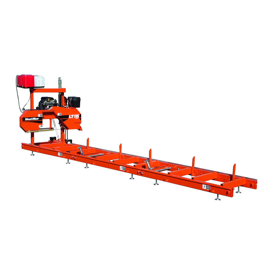
Wood-mizer LT15 Safety, Operation, Maintenance & Parts Manual
Load assist kit
Hide thumbs
Also See for LT15:
- User manual (105 pages) ,
- Safety, setup, operation & maintenance manual (102 pages) ,
- Safety, operation, maintenance & parts manual (33 pages)

Related Manuals for Wood-mizer LT15


Summary of Contents for Wood-mizer LT15
- Page 1 LT15 Load Assist Kit Safety, Operation, Maintenance & Parts Manual LT15LAK Rev. A1.00 Safety is our #1 concern! Read and understand all safety information and instructions before oper- ating, setting up or maintaining this machine. April 2008 Form #1540...
- Page 2 Active Patents assigned to Wood-Mizer, LLC Wood-Mizer, LLC has received patents that protect our inventions which are a result of a dedication to research, innovation, development, and design. Learn more at: woodmizer.com/patents ©2021 Wood-Mizer LLC Printed in the United States of America, all rights reserved. No part of this manual may be reproduced in any form by...
-
Page 3: Table Of Contents
Table of Contents Section-Page SECTION 1 LOAD ASSIST KIT INSTALLATION Winch .....................1-1 Wheel Assemblies ..................1-1 SECTION 2 LOAD ASSIST KIT OPERATION Loading....................2-1 Unloading ....................2-2 SECTION 3 LOAD ASSIST KIT REPLACEMENT PARTS Table of Contents LAKdoc042121... -
Page 4: Load Assist Kit Installation
SECTION 1 LOAD ASSIST KIT INSTALLATION The Load Assist Kit option is intended to assist a single person to load and unload the LT15 on and off a trailer. The option may be assembled to any LT15 model sawmill with two bed sections. If the LT15 is equipped with a third bed section, it must be removed before using the load assist option. - Page 5 Load Assist Kit Installation Wheel Assemblies 5. Replace the feed rope bracket and hardware. Install the provided 1/2” lock washer and jam nut to the bolt. 6. Continue the bolt through the wheel mount and secure with a flat washer and lock nut. NOTE: Feed rope bracket hardware will vary depending on bed revision.
- Page 6 Load Assist Kit Installation Wheel Assemblies 10. Install a wheel to each pivot arm and secure with a 5/8-11 hex nylon lock jam nut.See Fig. 1-5. 11. Assemble the left wheel assembly to the left wheel mount and secure with a retaining pin. 12.
-
Page 7: Load Assist Kit Operation
Load Assist Kit Operation Loading SECTION 2 LOAD ASSIST KIT OPERATION Loading DANGER! Keep all persons out of the path of moving equipment when loading or unloading sawmill. Follow all safety precautions provided in the winch manufacturer’s instructions. Failure to do so will result in serious injury. 1. -
Page 8: Unloading
3. Place the front locking pin in the operation position. The rear locking pin should already be in the operation position. See your LT15 operator’s manual for detailed locking pin operating instructions. 4. Make sure the winch strap is still hooked to the bracket on the motor mount plate. - Page 9 Load Assist Kit Operation Unloading 8. Push the saw head toward the rear of the sawmill until the winch strap is tight, just before the trailer tilts to the ground. 9. Grasp the winch handle securely and move the ratchet pawl to reverse. 10.
- Page 10 The left-side wheel must be removed to avoid interference with the saw head carriage during operation. The right-side wheel can remain assembled to the sawmill. 25. Reinstall or adjust the next-to-last outrigger legs. 26. See your LT15 operator’s manual for complete sawmill setup instructions. WM doc 4/21/21 Load Assist Kit Operation...
-
Page 11: Load Assist Kit Replacement Parts
Load Assist Kit Replacement Parts SECTION 3 LOAD ASSIST KIT REPLACEMENT PARTS 150160 DESCRIPTION ( INDICATES PARTS AVAILABLE IN ASSEMBLIES ONLY) PART # QTY. KIT, LT15 LOAD ASSIST LT15LAK Bracket Assembly, Right Wheel Mount 057498 Bracket Weldment, Wheel Mount 057451 Pin, 1/2”... - Page 12 Load Assist Kit Replacement Parts Bolt, 3/8-16 x 4 1/2” Hex Head F05007-35 Nut, 3/8-16 Hex Nylon Lock F05010-10 Bolt, 3/8-16 x 1” Hex Head Grade 5 F05007-87 Nut, 5/8-11 Hex Nylon Lock Jam F05010-96 Bolt, 1/2-13 x 3 1/2” Hex Head Full Thread F05008-11 Washer, 1/2”...
Need help?
Do you have a question about the LT15 and is the answer not in the manual?
Questions and answers