Avid Technology VENUE Stage 64 Replacement
Psu replacement
Hide thumbs
Also See for VENUE Stage 64:
- Installation manual (21 pages) ,
- Manual (9 pages) ,
- Replacement (5 pages)
Advertisement
Stage 64 PSU Replacement
This document shows how to replace the PSUs (Power Supply Units) in Avid
Stage 64 units have two PSUs for redundancy. The procedure is similar when replacing either PSU, and any differences are noted in this
guide.
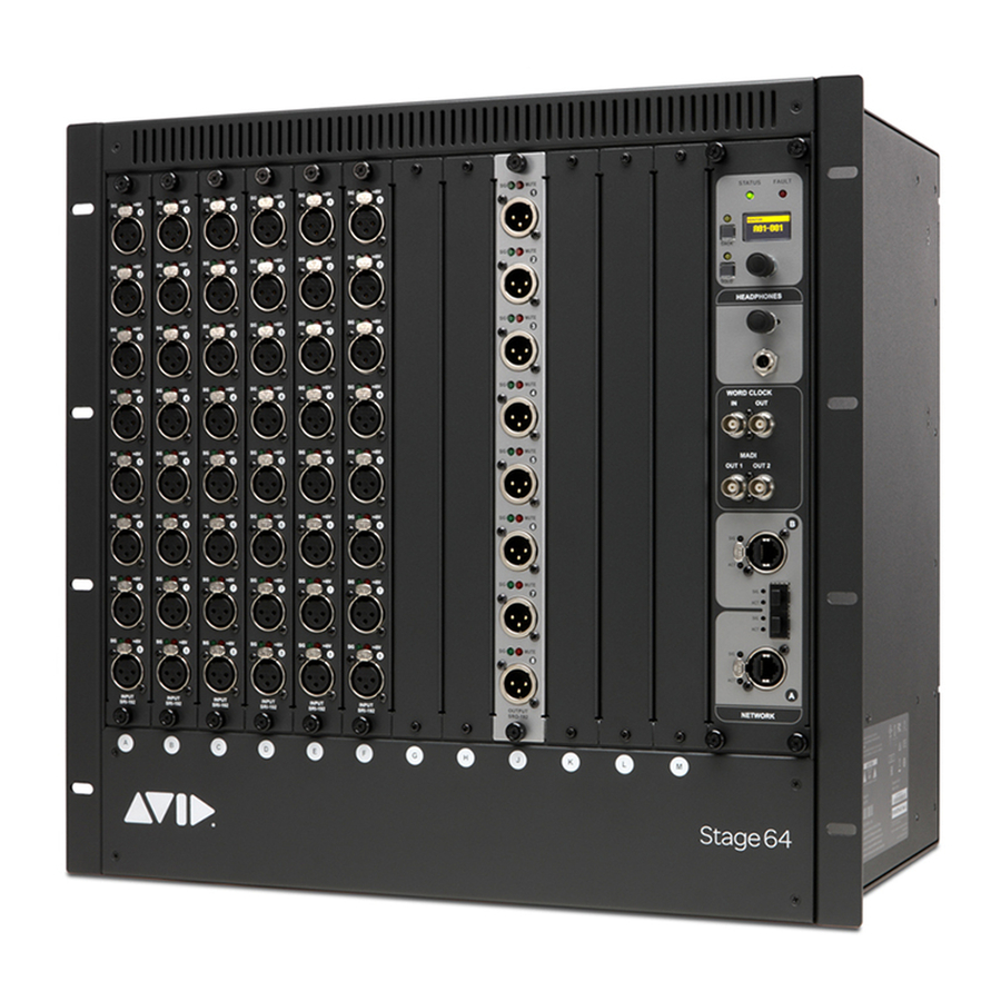
Left
Figure 1. Rear view of Stage 64 showing left and right PSUs (shown at left) and a replacement PSU (shown at right)
After collecting the required items, listed below, proceed to
Required Items
This procedure requires the following items:
• Replacement PSU
• 4x cable ties (nylon, 14W or similar)
• #1 Phillips screwdriver (6-inch or longer)
• A clean, padded work surface
• Anti-static wrist strap (not included). Make sure you are electrically grounded and discharge static before working
Prepare the I/O Rack Unit
Do the following to prepare your Stage 64:
Shut down your VENUE system and power down your Stage 64.
1
Disconnect all cables from your Stage 64.
2
Remove the back panel by loosening the eight captive thumbscrews completely, using a #2 Phillips screwdriver if necessary, and set
3
the panel aside.
Figure 2. Stage 64 back panel captive thumbscrews
Stage 64 PSU Replacement
Right
Prepare the I/O Rack Unit
®
VENUE Stage 64 I/O units.
.
9329-66178-00 REV A 08/20
Advertisement
Table of Contents

Related Manuals for Avid Technology VENUE Stage 64


Summary of Contents for Avid Technology VENUE Stage 64
- Page 1 This document shows how to replace the PSUs (Power Supply Units) in Avid VENUE Stage 64 I/O units. Stage 64 units have two PSUs for redundancy. The procedure is similar when replacing either PSU, and any differences are noted in this guide.
- Page 2 Remove the Old PSU To remove either the right or left PSU you must first remove all Input and Output cards from slots A–M. To remove a Stage 64 PSU: Identify which PSU (left or right, while facing the back of the unit) you will be replacing. Output slots J–M Input slots A–H Left PSU...
- Page 3 Loosen the captive thumbscrew securing each card to the chassis. Figure 5. Loosening captive thumbscrews Loosen the two captive thumbscrews securing the front of each card to the front of the IO unit. Figure 6. Loosening front panel captive thumbscrews Carefully slide each card out of its slot.
- Page 4 Move to the back of the Stage 64 and carefully disconnect the multi-colored PSU cable for the PSU you are replacing from the back of the Controller assembly. Left PSU (below Output cards) Right PSU (below Input cards) Figure 8. Controller PSU cable clips Using a #1 Philips screwdriver, remove the two screws indicated in Figure 9 that secure the power switch for the PSU being removed to the Stage 64 chassis.
- Page 5 Install the New PSU To install the new PSU: Carefully insert the new PSU into position in the Stage Rack. • Make sure the switch is aligned and passes through its opening in the chassis back panel. • Make sure the power harnesses are not underneath the PSU. •...
- Page 6 Figure 12. Securing a card Inside the back of the unit, push the latches on the card outward (open). Repeat for all other cards. Reconnect all ribbon cables, starting with the first (shortest) ribbon cable. Push the cable connector into the port on the card so that the latches on the port move inward and lock the connector to the port on the card.
Need help?
Do you have a question about the VENUE Stage 64 and is the answer not in the manual?
Questions and answers