Avid Technology VENUE Stage 64 Replacement
Controller assembly replacement
Hide thumbs
Also See for VENUE Stage 64:
- Installation manual (21 pages) ,
- Manual (9 pages) ,
- Replacement (6 pages)
Advertisement
Stage 64 Controller Assembly Replacement
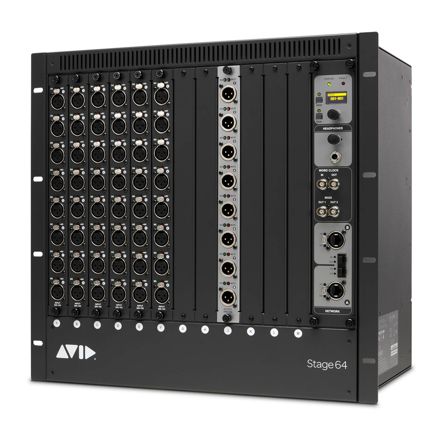
This document shows how to replace the Controller assembly in Avid
After collecting the required items, listed below, proceed to
Required Items
This procedure requires the following items:
• #1 Phillips screwdriver (6-inch or longer)
• A clean, padded work surface
• Anti-static wrist strap (not included). Make sure you are electrically grounded and discharge static before working
• Recommended: A known-good XLR cable to perform an audio loopback test
Prepare the I/O Rack Unit
Do the following to prepare your Stage 64:
Shut down your VENUE system and power down your Stage 64.
1
Disconnect all cables from your Stage 64.
2
Remove the back panel by loosening the eight captive thumbscrews completely, using a #2 Phillips screwdriver if necessary, and set
3
the panel aside.
Figure 1. Stage 64 back panel captive thumbscrews
S6L Module Installation
®
VENUE Stage 64 I/O units.
.
Prepare the I/O Rack Unit
9329-66071-00 REV A 09/19
Advertisement
Table of Contents

Subscribe to Our Youtube Channel
Related Manuals for Avid Technology VENUE Stage 64


Summary of Contents for Avid Technology VENUE Stage 64
- Page 1 Stage 64 Controller Assembly Replacement ® This document shows how to replace the Controller assembly in Avid VENUE Stage 64 I/O units. After collecting the required items, listed below, proceed to Prepare the I/O Rack Unit Required Items This procedure requires the following items: •...
- Page 2 Remove the Controller Assembly To remove the Stage 64 Controller assembly: Loosen the four captive thumbscrews that secure the Controller to the front of the chassis. Figure 2. Stage 64 Controller front panel captive thumbscrews Inside the back of the unit, loosen the captive thumbscrew that secures the Controller to the chassis. Figure 3.
- Page 3 Disconnect the 2x PSU cables and 1x signal cable from the back of the controller. Figure 5. Controller PSU cable clips (shown at left) and disconnecting the signal cable (shown at right) Using one hand to guide the I/O ribbon cables so they don’t get caught on the chassis frame, pull the Controller out through the front of the Stage 64.
- Page 4 Install the New Stage 64 Controller To install the new Stage 64 Controller Assembly: Hold the new Controller assembly in one hand while you carefully feed the ribbon cables into the Controller slot in the Stage 64. Gently push the Controller into the slot and, reaching in from the back of the Stage 64, continue guiding the ribbon cables through ahead the slot.
- Page 5 Confirming Installation To confirm installation: Connect the power cables to the Stage unit and to a power source. Connect the Stage unit to the rest of your S6L system using Ethernet or fiber. Power on your S6L system (engine, control surface, then Stage unit). Enable Config mode.
Need help?
Do you have a question about the VENUE Stage 64 and is the answer not in the manual?
Questions and answers