Advertisement
Available languages
Available languages
INSTRUCTION
EN
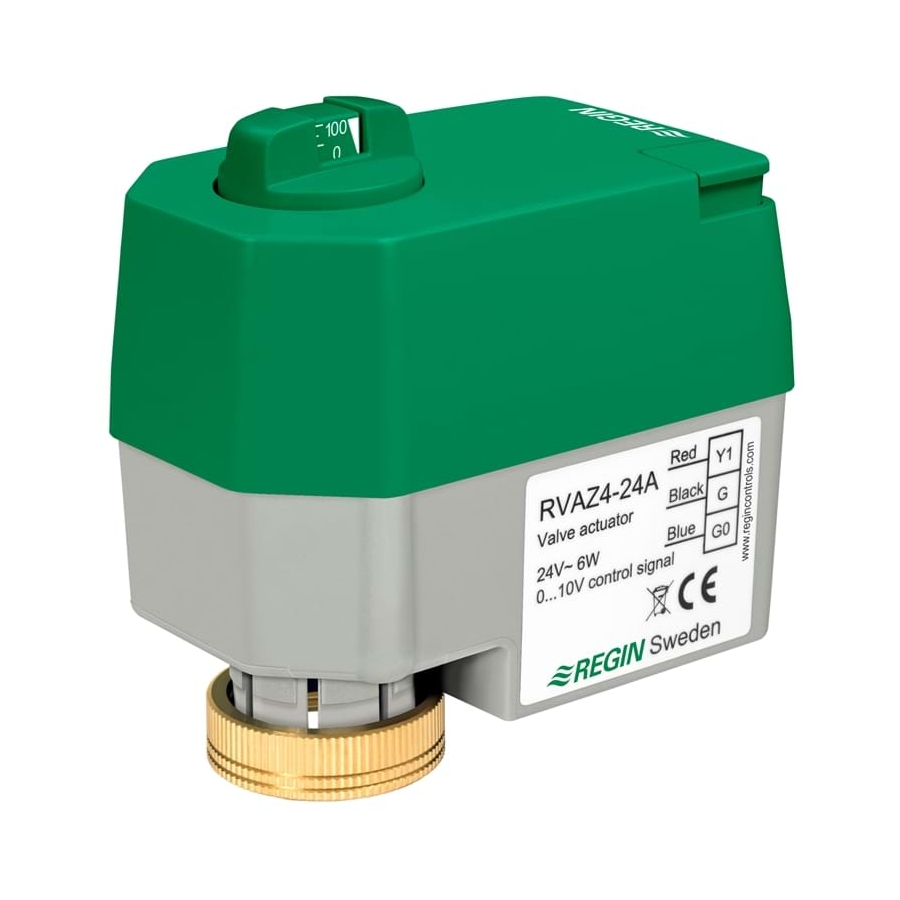
RVAZ4-24A
i
Read this instruction before installation
and wiring of the product
Valve actuator for 0...10 V control signal
RVAZ4-24A is intended to be used together with Regin's valves ZTV,
ZTR, ZTVB/ZTRB and ZMD.
Technical data
Supply voltage
24 V AC / DC ±15 %
Control signal
0...10 V DC
Power consumption
Max. 6 W
Stroke
5.5 mm
Stroke time
30 s
Force
400 N
Ambient temperature, operation
0...50°C
Media temperature
1...110°C
Storage temperature
-10...+80°C
Ambient humidity
Max 95 % RH
Measurements (W x H x L)
60 x 75.5 x 92 mm
Protection class
IP44
Cable length
2 m
Mounting
The valve should be mounted so that the drive rod on the actuator is
within 90° from the vertical line and the motor housing is on top. The valve
actuator's drive rod should be in its highest/innermost position when it is
mounted on the valve.
Fix the actuator to the valve using the connection nut, manual power is
sufficient.
90º
90º
Wiring
The actuator has a connection cable with a connector which is intended
for connection to the bottom of the actuator. There is only one way to plug
in the contact. Be careful not to damage the cable if the connector needs
to be removed from the actuator.
Connect the supply voltage and control signal. If the actuator and control-
ler share a transformer, it is very important to keep the phase separate
from the zero, so the same pole is used as zero for both controller and
actuator, since this is the reference for the control signal.
Red = control signal 0...10 V
Black = 24 V AC / DC (G) (+)
Blue = system neutral (G0) (-)
Controller, 0...10 V output
Control signal (0...10 V)
RED
Supply voltage (G) (+)
BLACK
System neutral (G0) (-)
BLUE
Manual manoeuvring
Before the actuator is set manually, the supply voltage must first be cut.
To set the valve position manually, hold down the disengagement button
(A in the picture below) and then turn the knob for manual manoeuvring
(B in the picture below) to the desired position. When the knob is turned
clockwise, the drive rod is pushed outwards and when the knob is turned
anti-clockwise, the drive rod is pulled inwards.
Position indication
RVAZ4-24A has a clear position indication which is shown on the
knob for manual manoeuvring. There are markings for 0, 25, 50, 75
and 100 % open position.
This product carries the CE-mark. More information is available at
www.regincontrols.com.
Contact
AB Regin, Box 116, 428 22 Kållered, Sweden
Tel: +46 31 720 02 00, Fax: +46 31 720 02 50
www.regin.se, info@regin.se
RVAZ4-24A
1
Advertisement
Table of Contents

Subscribe to Our Youtube Channel
Related Manuals for Regin RVAZ4-24A


Summary of Contents for Regin RVAZ4-24A
- Page 1 90º 90º Position indication RVAZ4-24A has a clear position indication which is shown on the knob for manual manoeuvring. There are markings for 0, 25, 50, 75 and 100 % open position. This product carries the CE-mark. More information is available at Wiring www.regincontrols.com.
- Page 2 RVAZ4-24A Ställdonet har en anslutningskabel med kontaktdon som är avsedd för RVAZ4-24A har en tydlig lägesindikering som avläses på hand- kontakteringen i ställdonets nederkant. Kontakten går bara att sätta i på manövervredet. Det finns markeringar för 0, 25, 50, 75 och 100 % Läs denna instruktion innan produkten...
- Page 3 RVAZ4-24A Der Stellantrieb hat ein Anschlusskabel mit einem Verbindungsstück, das RVAZ4-24A hat eine Positions-LED, die auf dem Knopf für die Hand- am Unterteil des Stellantriebs angebracht wird. Der Kontakt muss richtig bedienung angebracht ist. Die Markierungen gelten für 0, 25, 50, 75 Lesen Sie diese Anleitung, bevor Sie das gesteckt werden.
- Page 4 Utiliser les écrous pour solidariser la vanne et le moteur. Il n'y a pas besoin d'outils, la force manuelle suffit. 90º 90º Indicateur de position RVAZ4-24A est doté d'un indicateur de position situé sur le bouton B. Les repères correspondent à 0, 25, 50, 75 et 100% d'ouverture de la vanne.
Need help?
Do you have a question about the RVAZ4-24A and is the answer not in the manual?
Questions and answers