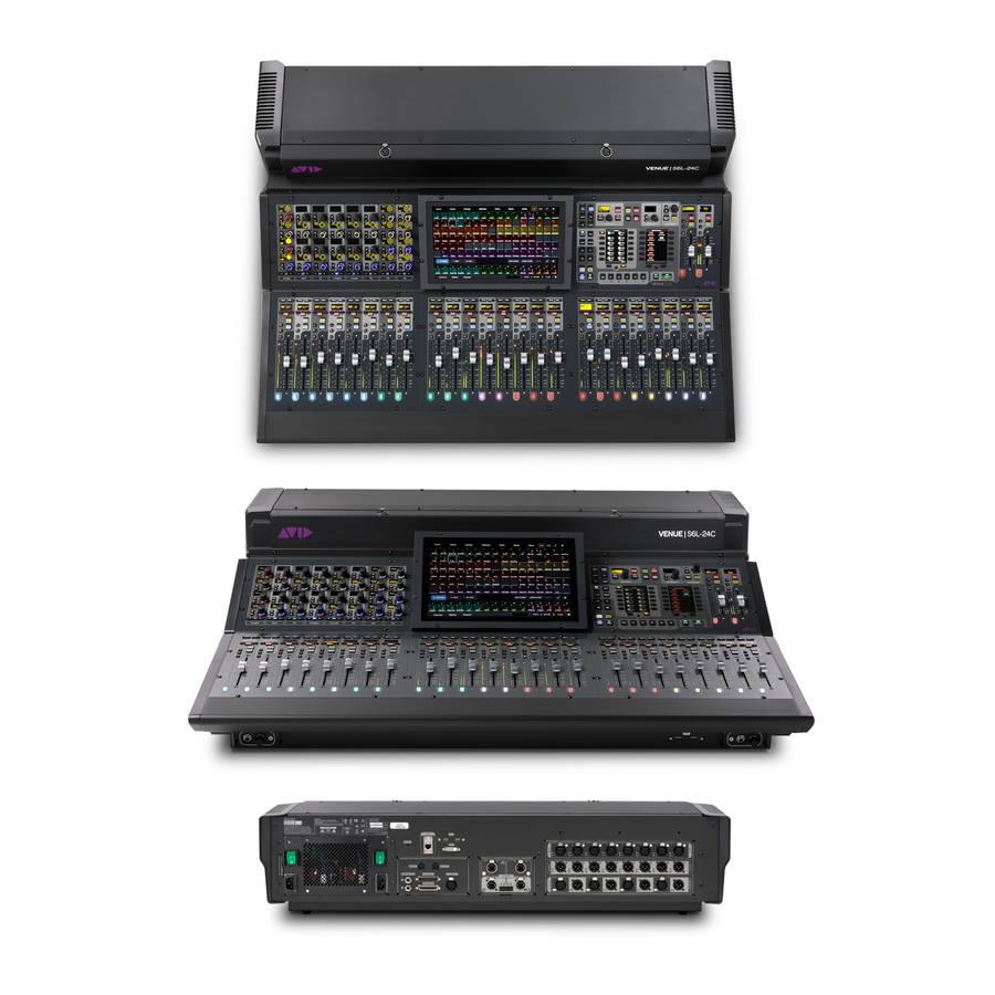
Avid Technology S6L Control Surface Replacing
Replacing the gpio board
Hide thumbs
Also See for S6L Control Surface:
- Replacing (31 pages) ,
- Installing (18 pages) ,
- Replacement (9 pages)
Advertisement
S6L Control Surface: Replacing the GPIO Board
This document provides instructions for replacing the GPIO board in the S6L Control Surface.
Before you Begin
Make sure to do all the following items before beginning the procedure.
Make sure you have assembled all
1
Put on your anti-static wrist band and configure according to its instructions.
2
Shut down your system, and disconnect any cables connected to your S6L control surface.
3
Make sure your work area is clear of any debris.
4
Throughout this procedure, keep the removed screws organized to simplify re-assembly.
Required Tools and Items
• 1x 2.5mm Hex driver
• 1x #2 Phillips screwdriver
• Anti-Static wrist strap (not included)
• Small cups or other containers to hold and organize the different types of fasteners as you remove them from the unit
• Table or other work surface strong enough to support the S6L control surface while allowing access to the back of the unit.
• Recommended for labeling cables: Camera (your phone or other) to document cable connections, or a pen and lightweight
tape to label cables as you disconnect them.
What's Included
• 1x Replacement GPIO board assembly
Figure 1. GPIO board assembly
S6L Control Surface: Replacing the GPIO Board
9329-65919-00 REV A
.
Required Tools and Items
1
Advertisement
Table of Contents

Subscribe to Our Youtube Channel
Summary of Contents for Avid Technology S6L Control Surface
- Page 1 • Small cups or other containers to hold and organize the different types of fasteners as you remove them from the unit • Table or other work surface strong enough to support the S6L control surface while allowing access to the back of the unit.
- Page 2 1. Prepare the S6L Control Surface Prepare the S6L control surface by removing the back cover and specific modules as explained in the following sections. Remove the S6L Back Cover To remove the S6L Back Cover: Using a 2.5mm Hex driver, remove the 8 fasteners that secure the back cover to the S6L chassis and set the screws aside.
- Page 3 (up), then carefully pull the ribbon cable away from the connector. Figure 4. Cable to disconnect from the upper daughter board (shown at left) and ZIF cable from the main GPIO board (shown at right) S6L Control Surface: Replacing the GPIO Board...
- Page 4 Place new GPIO assembly in position in the chassis, making sure to orient it correctly and to insert it fully so that its exterior faceplate and exterior ports are seated correctly against the back wall of the chassis. Tighten the 4 captive screws that secure the GPIO board assembly to the chassis. S6L Control Surface: Replacing the GPIO Board...
- Page 5 Figure 7. Example photo of the GPIO assembly with cables connected • If necessary, remove any labels you applied to the cables. Proceed to 4. Complete the Installation S6L Control Surface: Replacing the GPIO Board...
- Page 6 4. Complete the Installation After installing the new GPIO board assembly, re-assemble the S6L control surface. Replace the S6L Back Cover To replace the S6L Back Cover: Making sure to orient the back cover correctly, slide the cover back into position on the control surface.


Need help?
Do you have a question about the S6L Control Surface and is the answer not in the manual?
Questions and answers