Table of Contents
Advertisement
Quick Links
Advertisement
Table of Contents

Related Manuals for W&H Perfecta 900


Summary of Contents for W&H Perfecta 900
- Page 1 Instructions for use Translation of the original operating manual...
-
Page 2: Table Of Contents
Contents W&H Symbols . . . . . . . . . . . . . . . . . . . . . . . . . . . . . . . . . . . . . . . . . . . . . . . . . . . . . . . . . . . . . . . . . . . . . . . . . . . . . . . . . . . . . . . . . . . . . . . . . . . . . . . 3 – 5 Introduction . -
Page 3: W&H Symbols
W&H Symbols Symbols in the instructions for use WARNING! ATTENTION! General explanations, (Risk of injury) (to prevent damage occurring) without risk to persons or objects W&H Service Only for USA Caution: Federal law restricts this device to sale by or on the order of a dentist, physician or any other practitioner licensed by the law of the state in which he or she practices to use or order the use of the device . - Page 4 W&H Symbols Symbols on the control unit Consult instructions for use Do not dispose of with Catalogue number domestic waste Date of manufacture Foot switch Serial number Electric fuse Motor Supply voltage of the unit Data Matrix Code, Operating controls Alternating current only for certain models, for product identification...
- Page 5 W&H Symbols Symbols on the packaging This way up Temperature limit Caution: Federal law restricts this device to sale by or on the order of a dentist, physician or any other practitioner licensed by the Fragile, handle with care Humidity limitation law of the state in which he or she practices to use or order the use of the device...
-
Page 6: Introduction
1. Introduction For your safety and the safety of your team These Instructions for use explain how to use your W&H product . However, we must also warn against possible hazardous situations . Your safety and the safety of your team are of paramount importance to us . It is therefore essential to read the safety notes on Pages 11 to 12 . - Page 7 Introduction The Perfecta is in the condition as supplied by us > safety checked > carries the UL mark of quality > suppressed in accordance with pertinent standards . This declaration is not valid for unintended external or internal attachments and the like . Responsibility of the manufacturer W&H Dentalwerk Bürmoos can only accept responsibility for the safety, reliability and performance of the Perfecta when there is compliance with the following directions:...
-
Page 8: Unpacking
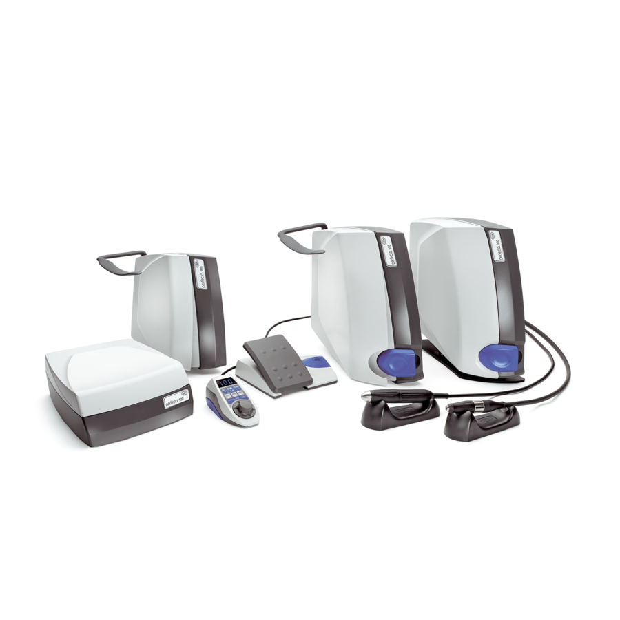
2. Unpacking W&H packaging is environmentally friendly and can be Lift out the accessories carton . disposed of through branch recycling companies . However, we recommend that you keep the original packaging . Knee control unit: Remove the holding plate and fitting for the blow out function . - Page 9 3. Perfecta 900 equipment supplied with internal coolant supplying Knee control unit Table control unit Knee-, Table control unit Control unit: Control unit: Motor cable 1 .8 m for LA-9 REF 05117800 REF 05223900 230 V REF 05223500 230 V...
- Page 10 Perfecta 900 equipment supplied with external coolant supplying Knee control unit Table control unit Knee-, Table control unit Control unit: Control unit: Motor cable 1 .8 m for LA-9 REF 05117800 REF 05333600 230 V REF 05334200 230 V Hose for air supply REF 05250400...
-
Page 11: Safety Notes
4. Safety notes Please ensure that you carry out the following instructions > Before using the Perfecta for the first time, store it at room temperature for 24 hours . > Only connect the Perfecta to a socket outlet with protective earthing .w >... - Page 12 Safety notes Danger zone The control unit is not suitable for use in areas in which special conditions prevail (e .g . corrosive or explosive atmospheres) . Power failure In the event of a power failure or if the Perfecta is switched off, the last speed set is saved and re-activated on power-up . Intermittent operating mode S6 (4min/10min) is the designation for continuous operation with intermittent loading .
- Page 13 5. Description of knee control unit Fitting for blow out function Connecting socket for motor handpiece Coolant regulator LA-9 Power socket LA-66 (optional) Fuse holder with 2 fuses Connecting socket for foot- operated starter (optional) Connecting socket for Power switch ON / OFF (I / 0) operating controls Coolant supply (control unit with Air supply...
- Page 14 Knee control unit assembly Mark the screw holes with the enclosed drilling template or holding plate . Pre-drill 4 screw holes with ø 3 mm . Note dimensions: 550 to 600 mm H1 = at least 90 mm 90 mm (control unit with external coolant supplying) 125 mm (control unit with internal coolant supplying) measured from the front edge of the bench...
- Page 15 Knee control unit operation Before connect or disconnect mains cable, motor cable, operating controls, foot-operated starter (optional), air hose, coolant hose (control unit with external coolant supplying) switch off the control unit . Push in the fitting for the blow Insert control unit up to the out function up to the limit stop .
- Page 16 6. Description of table control unit with internal coolant supplying Connecting socket for motor handpiece Coolant regulator LA-9 LA-66 (optional) Power socket Connecting socket for foot- Fuse holder with 2 fuses operated starter (optional) Connecting socket for operating controls Power switch ON / OFF (I / 0) Air supply Foot stand Production year...
- Page 17 Description of table control unit with external coolant supplying Connecting socket for Connecting socket for foot- Connecting socket for motor handpiece operated starter operating controls LA-66 (optional) LA-9 Air supply Coolant supply Coolant regulator Power socket Fuse holder with 2 fuses Power switch ON / OFF (I / 0) Production year...
-
Page 18: Description / Starting Operation - Table Control Unit
Starting operation – Table control unit Assemble the control unit onto the Foot-operated starter foot stand with compressed operating panel (control unit with internal coolant supplying) . Note the positioning! Connect the motor cable, operating controls, foot-operated starter, air hose, Pedal for Push buttons for coolant hose (control unit with external... -
Page 19: General Starting Operation - Filling Of The Coolant Tank / Regulating Coolant
7. General starting operation – Filling of the coolant tank By ventilation at the first filling or if the coolant tank was emptied completely during work, it can coming to delays in coolant escaping . W&H recommend the use of distilled water . ... - Page 20 General starting operation – Regulating coolant Increase coolant . Decrease coolant .
- Page 21 8. Description of the motor handpiece LA-9 / Adaptor for milling device (optional) Motor handpiece LA-9 Sheath Expansion ring Motor cable The milling device adaptor (optional) for the motor handpiece can be fastened above or below the expansion ring . The milling device adaptor (optional) has a diameter of 16 or 18 mm on either side for use with different milling devices .
- Page 22 Description of the motor handpiece LA-66 (optional) Motor handpieceLA-66 (optional) Front sheath Rear sheath Motor cable...
-
Page 23: General Operation - Motor Handpiece / Blow Out Function
9. General operation – start motor handpiece / blow out function Start motor handpiece by pressing the knee control unit or the foot-operated starter . Activate the blow out function by constantly pressing the button or fitting . - Page 24 10. Description of operating controls Display Forward / reverse operation mode Changing motor handpiece Coolant spray Speed control operation Program button Program button Forward / reverse Bistable operation / operation mode Speed control operation Bistable operation Program button Changing motor handpiece / coolant supplying Control knob for speed regulation...
-
Page 25: Description Of The Operating Controls / Assemble Support (Optional)
Description of the operating controls – Assemble support (optional) Assemble the support (optional) . The support (optional) can be moved into a variety of assembly positions by simultaneously pressing both buttons on the joint . - Page 26 11. Operating controls – Reverse operation mode You can switch between forward and reverse operation by pressing the program button . When switching to reverse operation, an audible signal sounds and the LED illuminates .
- Page 27 Operating controls – Changing the speed By turning the PLUS / MINUS control knob, the values 5 .000 – 80 .000 rpm (LA-66 (optional) 1 .000 – 40 .000 rpm) are continuously increased / decreased . Increase speed . Decrease speed .
- Page 28 Operating controls – Changing motor handpiece / Coolant supplying By deactivation of the program button it can be changed to motor handoiece LA-66 (optional) . Keep the program button Start motor handpiece by pressed fter approx . pressing the pedal or flap . 2 seconds, an audible signal sounds .
- Page 29 Operating controls – Bistable operation During bistable operation, the selected maximum speed is automatically reached during motor start . he motor handpiece runs independently . Deactivation of bistable operation: Press program button x 2 . Press the button . Start or stop the motor The LED illuminates .
- Page 30 Operating controls – Speed control operation During speed control operation, the controlled speed is saved and automatically maintained . The motor handpiece runs independently . Deactivation of speed control operation: Press the program button x 1 . Press the button x 2 . Stop the motor handpiece by LED illuminates .
-
Page 31: Removing And Assembling The Motor Handpiece
12. Removing and assembling the motor handpiece LA-9 Unscrew the cap . Assemble and tighten the cap . Note the positioning! LA-66 (optional) Unscrew the cap . Assemble and tighten the cap . Note the positioning! - Page 32 13. Change the rotary tool LA-9 Turn the expansion ring Turn the expansion ring anti- clockwise up to the limit clockwise until it engages stop . Push in the rotary audibly . tool up to the limit stop or remove .
- Page 33 Change the rotary tool When the chuck is open, the motor handpiece is blocked . In the event that the motor handpiece starts accidentally, the electronic system switches off . Test run > Start the motor handpiece . > In the event of malfunctions (e .g . vibrations, unusual noises, overheating), stop the motor immediately und contact an authorized W&H service partner (see page 45) .
-
Page 34: Cleaning
14. Cleaning The cleaning of the Perfecta (control unit), motor handpiece, operating controls (optional), foot-operated starter (optional) can take place by means of a dry cloth . - Page 35 15. Cleaning / changing the chuck LA-66 (optional) Chuck key, spanner, cleaning brush are located on the underside of the handpiece holder . Turn the front sheath clockwise up to the limit stop . Unscrew the tip anti-clockwise . ...
-
Page 36: Cleaning / Changing The Chuck
Cleaning / changing the chuck Clean the inside and outside of the shaft using the cleaning brush . Apply 2 drops of oil into the hole in the shaft and outside of the chuck . Insert the chuck . ... -
Page 37: Error Messages
16. Error messages (as shown on display) Error No. Description Remedy Switch off the equipment, cool for at least 10 minutes Electronics overheating – safety shutdown and then re-start Connect motor handpiece or close the chuck Motor handpiece overloading – Drive blocked mechanism Switch off the equipment, re-start, do not activate the Foot-operated starter error initialising... -
Page 38: W&H Accessories
Use only original W&H accessories / spare parts 17. W&H Accessories or accessories approved by W&H 03211500 Handpiece holder 04014700 Fuse T1 .25L 01199100 Fuse T2A 05117800 Motor cable 1,8 m LA-9 05015900 Motor handpiece LA-9 (without motor cable) 05038100 Foot-operated starter L-NV 05075600 Hose for coolant supply... -
Page 39: Servicing
18. Servicing Repairs If a defect occurs, always return all the equipment, due to the fact that with motor malfunctions, an inspection of the electronic controls is also necessary! We recommend that only an authorized W&H service partner should undertake this servicing and checking . Returns >... - Page 40 19. Technical Data Perfecta 900 with motor handpiece LA-9 LA-66 (optional) Mech . output power 30 W 160 W Torque 0 .7 Ncm 7 .8 Ncm Speed 5,000 – 100,000 rpm 1,000 – 50,000 rpm Power input 200 W Supply voltage 100 –...
-
Page 41: Technical Data
Technical Data Physical characteristics Temperature in storage: -40 °C (-40 °F) to +70 °C (+158 °F) Air humidity in storage: 8 % to 80 % (relative), non-condensing Temperature in operation: +5 °C to +40 °C Air humidity in operation: maximum 80 % (relative) with a temperature of up to +31°C, decreasing arithmetically up to a maximum of 50 % (relative) with a temperature of up to +40°C Pollution degree:... -
Page 42: Recycling And Disposal
20. Recycling and Disposal Recycling W&H considers that it has a special duty towards the environment . The Perfecta equipment along with its packaging has been designed to be as environmentally friendly as possible . Disposal of the Perfecta (control unit), operating controls, foot-operated starter, motor handpiece Follow your country-specific laws, directives, standards and guidelines for the disposal of used electrical devices . - Page 43 Expla n at io n o f w ar r a nty t e rms This W&H product has been manufactured with great care by highly qualified specialists . A wide variety of tests and controls guarantee faultless operation . Please note that claims under warranty can only be validated when all the directions in the Instructions for use have been followed .
-
Page 44: Ce-Declaration Of Conformity
CE-Declaration of conformity... -
Page 45: Authorized W&H Service Partners
Authorized W&H service partners Find your nearest W&H service partner at http://wh .com Simply go to the menu option »Service« for full details . Alternatively please contact: W&H (UK) LIMITED, Unit 6, Stroud Wood Business Centre, Park Street, St Albans, Hertfordshire AL2 2NJ, United Kingdom t + 44 1727 874990, f + 44 1727 872254, E-Mail: technical .uk@wh .com W&H Impex Inc., 6490 Hawthorne Drive, Windsor, Ontario, N8T 1J9, Canada t + 1 800 2656277, 1 519 9446739, f + 1 519 9746121, E-Mail: service .ca@wh .com... - Page 46 Manufacturer W&H Dentalwerk Bürmoos GmbH Ignaz-Glaser-Straße 53, 5111 Bürmoos, Austria Form-Nr . 50596 AEN t +43 / 6274 / 6236-0, f +43 / 6274 / 6236-55 Rev . 011 / 19 .04 .2016 office@wh .com wh.com Subject to alterations...
Need help?
Do you have a question about the Perfecta 900 and is the answer not in the manual?
Questions and answers