Table of Contents
Advertisement
Quick Links
__
_________
l � -'
-------- - -
,
Автоматическая установка компенсации реактивной мощности Socomec Cosys -
руководство по эксплуатации. Юниджет
Постоянная ссылка на страницу:
https://www.uni-jet.com/catalog/kompensatoryi-reaktivnoj-
un
Jet
moshhnosti/avtomaticheskaya-ustanovka-socomec-cosys-pfc.html
I
Advertisement
Table of Contents

Related Manuals for socomec COSYS PFC Series


Summary of Contents for socomec COSYS PFC Series
- Page 1 _________ l � -' -------- - - Автоматическая установка компенсации реактивной мощности Socomec Cosys - руководство по эксплуатации. Юниджет Постоянная ссылка на страницу: https://www.uni-jet.com/catalog/kompensatoryi-reaktivnoj- moshhnosti/avtomaticheskaya-ustanovka-socomec-cosys-pfc.html...
- Page 2 Automatic COSYS PFC system Operating instructions...
-
Page 3: Table Of Contents
WARRANTY CONDITIONS _________________________3 GENERAL SAFETY AND USAGE INSTRUCTIONS __________________________________4 SYSTEM DESCRIPTION ___________________________5 General points __________________________________5 Function ______________________________________5 Construction ___________________________________5 General characteristics ___________________________5 PFC system schematic diagram ___________________6 INSTALLATION ___________________________________7 Recommendations relating to installation conditions __________________________7 Connecting the input cables ______________________7 Upstream protection and connection cross section ___7 Technical characteristics _________________________8 COMMISSIONING AND MAINTENANCE ___________12... -
Page 4: Warranty Conditions
Automatic COSYS PFC system WARRANTY CONDITIONS The warranty conditions are set out in the sales contract; length of the warranty period. in all other cases, the following conditions shall apply. In order to benefit from this warranty, buyers must The manufacturer guarantees its product against any expressly inform the manufacturer - within a maximum manufacturing or operating faults caused by errors of 8 days, beyond which the warranty shall expire –... -
Page 5: General Safety And Usage Instructions
“Maintenance” paragraph on page 13 must be carried out at least once every 12 months. Failure to follow this instruction shall release Socomec from all liability with regard to the incorrect operation of the equipment and the consequences thereof. -
Page 6: System Description
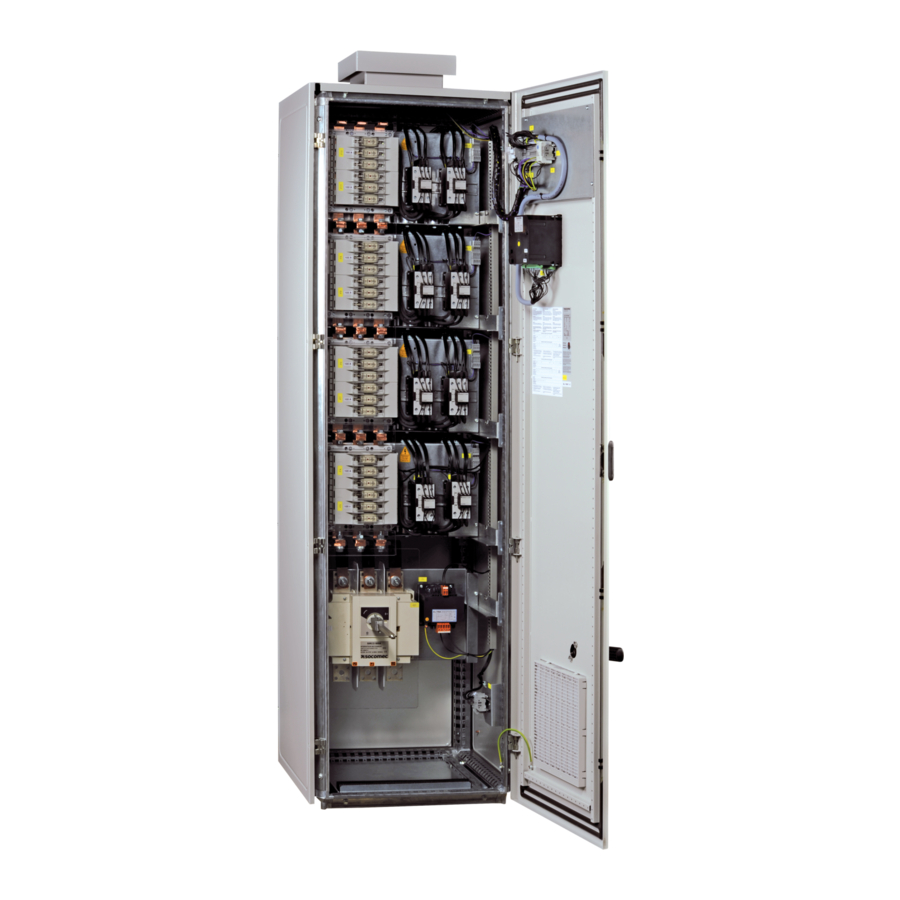
Automatic COSYS PFC system SYSTEM DESCRIPTION General points The equipment consists of one or several racks The racks are divided into steps which are connected of capacitors installed in an enclosure. Each rack or disconnected automatically, according to the reactive represents a reactive power expressed in kVAR. power required. Function The COSYS automatic PFC PFC system are designed to offset variable reactive energy. -
Page 7: Pfc System Schematic Diagram
SYSTEM DESCRIPTION PFC system schematic diagram 230V (140°) (140°) Wiring diagram with regulator COSYS R 12H We would advise fitting a PTI (current transformer automatic short-circuiter) to the current transformer secondary to prevent any electrical risks when the current transformer is disconnected (current transformer and PTI not supplied). Automatic COSYS PFC system - Ref. -
Page 8: Installation
Automatic COSYS PFC system INSTALLATION Failure to follow the installation instructions contained in this manual may compromise the operation and reliability of the PFC system. Recommendations relating to installation conditions Recommended operating temperature: between 15°C It is essential to ensure that there is a clearance of 50 cm and 35°C. above the PFC system to allow adequate ventilation. Relative humidity without condensation: 90% max. -
Page 9: Technical Characteristics
INSTALLATION Technical characteristics COSYS PFC41 Power I nominal Upstream protection Figure n° Height x Width x Depth Weight Regulator supply (without (with Kvar GG fuse (A) Fuserbloc (A) mm with switch switch) switch) 17.5 500x500x300 500x500x300 COSYS R 6H 500x500x300 500x500x300 COSYS R 6H 500x500x300... - Page 10 Automatic COSYS PFC system INSTALLATION Technical characteristics COSYS PFC43 Power I nominal Upstream protection Figure n° Height x Width x Depth Weight Regulator supply (without (with Kvar GG fuse (A) Fuserbloc (A) mm with switch switch) switch) 1211x600x311 1211x600x311 COSYS R 6H 1211x600x311 1211x600x311 COSYS R 6H...
- Page 11 INSTALLATION Figure 1 Ø7 Ø30 Figure 2 Ø7 Socle (option) Ø30 Figure 3 Ø7 Ø30 Socle (option) Figure 4 600/800 400/500 Automatic COSYS PFC system - Ref. : 539931A...
- Page 12 Automatic COSYS PFC system INSTALLATION Ø30 Socle (option) Figure 4 600/800 400/500 62,5 62,5 Socle (option) Ø11 400/600 Figure 5 600/800 Ø14 Socle (option) 420/620 Automatic COSYS PFC system - Ref. : 539931A...
-
Page 13: Commissioning And Maintenance
COMMISSIONING AND MAINTENANCE Checking the equipment Operating faults Before commissioning the equipment, ensure that all The most common reasons for operational failure connections are correctly tightened, as the terminals usually relate to the current transformer (see list below): may become loose during transportation of the equip- • ... -
Page 14: Maintenance
• O peration of the switches and retightening of their terminals • V isual inspection of the capacitors by replacing those that are causing deforming of the upper part of the outer enclosure. SOCOMEC can also offer: • maintenance • audit • start-up • training for your staff Automatic COSYS PFC system - Ref. : 539931A... - Page 15 Automatic COSYS PFC system - Ref. : 539931A...
- Page 16 Automatic COSYS PFC system Automatic COSYS PFC system - Ref. : 539931A...
- Page 17 F - 67235 Benfeld Cedex - FRANCE F-67235 Benfeld Cedex - FRANCE Tel. +33 (0)3 88 57 41 41 - Fax +33 (0)3 88 74 08 00 info.scp.isd@socomec.com www.socomec.com Non contractual document. © 2012, Socomec SA. All rights reserved. VALID FOR FRANCE...
Need help?
Do you have a question about the COSYS PFC Series and is the answer not in the manual?
Questions and answers