
Related Manuals for Humanscale M/FLEX


Summary of Contents for Humanscale M/FLEX
- Page 1 9-16 M/Connect 2 M/Power Assembly Instructions North America: +1 800 400 0625 Europe: +353 (0)1 858 0910 Asia Pacific: +852 2581 0570...
-
Page 2: Installation Hardware
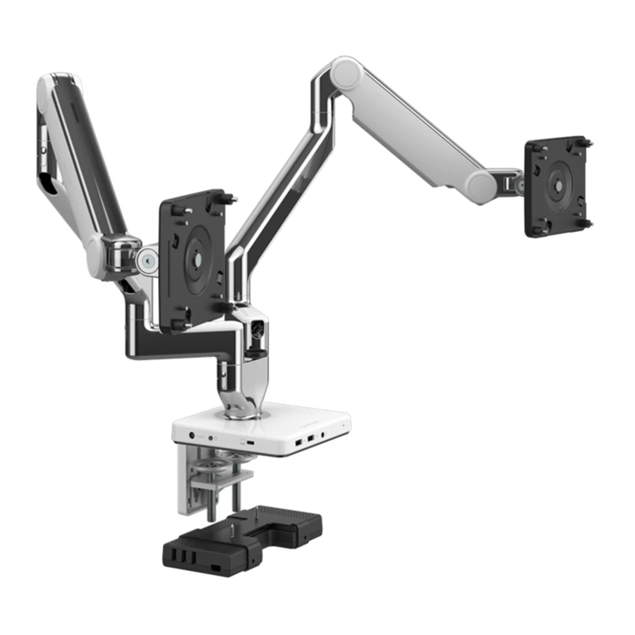
INSTALLATION HARDWARE Cable Routing Hook 3 mm 4 mm 5 mm Hex Key Hex Key Hex Key With Each VESA Plate: VESA Plate and Cover 4 Standard VESA 4 Plastic Spacers 4 Extended VESA Bracket Screws Bracket Screws... - Page 3 STEP 1: ATTACH MOUNT TO WORK SURFACE Before you install your new M/Flex and monitor arms you will need to set up your M/Connect 2 or M/Power base. Before proceeding, please refer to the installation manual that came with your M/Connect 2 or M/Power for instructions on mounting the base to your work surface.
- Page 4 CABLE ROUTING HOOK 1. Spread the hooks around the post in the desired location. 2. Squeeze the two sides until the Lock (K) snaps together. 3. To release, use fingernail to disengage the Lock. STEP 3: SMART STOP ADJUSTMENT A Smart Stop Ring is included at every Quick Attach joint. Position the Smart Stop Ring to limit the arm’s range of motion.
- Page 5 STEP 5: ATTACH VESA BRACKET TO MONITOR 1. Separate the VESA cover from the VESA plate. 2. Position the VESA plate over the mounting holes on the back of monitor with the D-shaped cutouts (A) in a vertical orientation. Attach using provided VESA screws. 3.
-
Page 6: Step 7: Cable Management
STEP 7: CABLE MANAGEMENT 1. Route power and monitor cables through the flexible Cable Clips (A) on the Upper Link. 2. Slide the Cover (B) off of the Straight Link. 3. Route cables into the Straight Link and replace the Cover, sliding until it clicks into place. - Page 7 STEP 9: M/FLEX CLAMP ADJUSTMENTS Your M/Flex arrives ready for use, however it may become necessary to adjust the clamp. 1. Remove monitors and links from the Bracket. 2. Open the Lever (A) all the way. 3. Turn the Adjustment Screw (B) clockwise ¼ of a turn using the 3 mm hex key (C).
- Page 8 © 2021 Humanscale Corporation. The text and artwork are copyrighted materials. All rights reserved. The Humanscale mark and logo are trademarks of Humanscale Corporation and are registered in the United States and certain other countries. The M/Flex trademark is owned by Humanscale Corporation. humanscale.com...
- Page 9 9-16 M/Connect2 M/Power Instructions d’assemblage Amérique du Nord : +1 800 400-0625 Europe : + 353 (0)1 858-0910 Asie pacifique : + 852 2581-0570...
-
Page 10: Matériel D'installation
MATÉRIEL D'INSTALLATION Crochet Clé Clé Clé d'acheminement hexagonale hexagonale hexagonale des câbles de 3 mm de 4 mm de 5 mm Inclus avec chaque plaque VESA : Plaque et couvercle 4 vis de support 4 entretoises en 4 vis de support VESA VESA VESA standard plastique... - Page 11 ÉTAPE 1 : FIXER LE SUPPORT À LA SURFACE DE TRAVAIL Avant d'installer votre nouveau M/Flex et vos bras d'écran, vous devrez configurer votre base M/Connect 2 ou M/Power. Avant de continuer, veuillez vous reporter au manuel d’installation fourni avec votre M/Connect 2 ou M/Power pour les instructions de montage de la base sur votre surface de travail.
- Page 12 CROCHET D’ACHEMINEMENT DE CÂBLES 1. Écartez les crochets autour de la colonne à l’emplacement souhaité. 2. Serrez les deux côtés jusqu’à ce que le verrou (K) s’enclenche. 3. Pour libérer, utilisez l’ongle pour désengager le verrou. ÉTAPE 3 : RÉGLAGE DE LA BUTÉE INTELLIGENTE Une bague de butée intelligente est incluse à...
- Page 13 ÉTAPE 5 : FIXER LE SUPPORT VESA À L’ÉCRAN 1. Enlevez le couvercle VESA de la plaque VESA. 2. Placez la plaque VESA sur les trous de montage à l’arrière de l’écran en orientant les découpes en forme de D (A) à la verticale. Fixez à l’aide des vis VESA fournies. 3.
- Page 14 ÉTAPE 7 : GESTION DES CÂBLES 1. Acheminez les câbles d’alimentation et de l’écran à travers les serre-câbles flexibles (A) sur le bras supérieur. 2. Faites glisser le couvercle (B) hors du bras droit. 3. Acheminez les câbles dans le bras droit et remettez en place le couvercle en le faisant glisser jusqu’à...
- Page 15 ÉTAPE 9 : AJUSTEMENTS DE LA PINCE M / FLEX Votre pince M/Flex est livrée prête à l’emploi, mais il peut s’avérer nécessaire de l’ajuster. 1. Retirez les écrans et les bras du support. 2. Ouvrez complètement le levier (A).
- Page 16 © 2021 Humanscale Corporation. Le texte et les illustrations de ce document sont protégés par des droits d'auteur. Tous droits réservés. La marque ainsi que le logo de Humanscale sont des marques de commerce de Humanscale Corporation et sont enregistrés aux États-Unis ainsi que dans certains pays. La marque M/Flex est la propriété de Humanscale Corporation. humanscale.com...
Need help?
Do you have a question about the M/FLEX and is the answer not in the manual?
Questions and answers