Table of Contents
Advertisement
Quick Links
Advertisement
Table of Contents
Troubleshooting

Related Manuals for Vollrath STOELTING A118-102


Summary of Contents for Vollrath STOELTING A118-102
- Page 1 A VOLLRATH® DIVISION Model A118 & D118 OPERATORS MANUAL Manual No. 513715 Rev.2...
- Page 3 Stoelting White Glove Service. For warranty information, visit stoeltingfoodservice.com Stoelting Foodservice Equipment White Glove Service Network 502 Highway 67 Phone: 888.319.9549 Kiel, WI 53042-1600 A VOLLRATH® DIVISION U.S.A. © 2020 Stoelting stoeltingfoodservice.com...
- Page 4 A Few Words About Safety Safety Information Safety Alert Symbol: Read and understand the entire manual before This symbol Indicates danger, warning or caution. operating or maintaining Stoelting equipment. Attention is required in order to avoid serious personal injury. The message that follows the symbol contains This manual provides the operator with information important information about safety.
-
Page 5: Table Of Contents
Table of Contents Section Description Page Section 1 - Description and Specifi cations Description........................1 Machine Models ......................1 Specifi cations ........................2 Section 2 - Installation Instructions Safety Precautions ......................3 Shipment and Transit ....................3 Machine Installation.......................3 Section 3 - Initial Set-Up & Installation Operator’s Safety Precautions ..................5 Operating Controls and Indicators ................5 Removing Mix from Machine ..................6... -
Page 7: Section 1 - Description And Specifi Cations
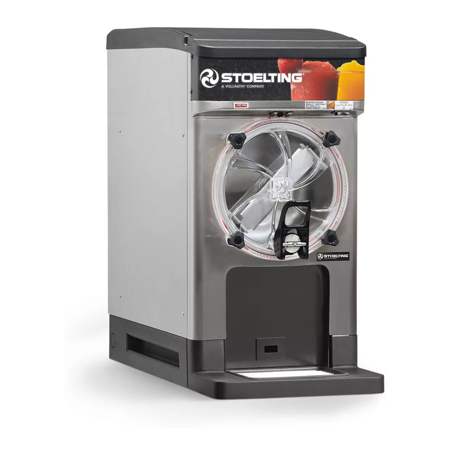
Section 1 - Description and Specifi cations DESCRIPTION Stoelting’s Frozen Uncarbonated Beverage Dispensers mix and serve a variety of frozen beverages including margaritas, slushes, coff ee drinks, and dairy-based prod- ucts. They are the ideal choice for bars and restaurants looking for fl... -
Page 8: Specifications
SPECIFICATIONS Model A118 Model D118 Dimensions Machine with crate Machine with crate width 16’’ (40,6 cm) 20’’ (50,8 cm) 16’’ (40,6 cm) 20’’ (50,8 cm) height 32-1/2’’ (82,6 cm) 39-3/4’’ (101,0 cm) 32-1/2’’ (82,6 cm) 39-3/4’’ (101,0 cm) depth 29’’ (73,7 cm) 41-1/2’’... -
Page 9: Section 2 - Installation Instructions
Section 2 - Installation Instructions SAFETY PRECAUTIONS Place the CLEAN-ON-OFF switch in the OFF position. Connect the power cord to the proper power supply. Do not attempt to operate the machine until the safety Refer to the nameplate on your machine for proper precautions and operating instructions in this manual are supply. - Page 10 Operators Manual #513715 A118 & D118 Model Machines...
-
Page 11: Section 3 - Initial Set-Up & Installation
Section 3 - Initial Set-Up & Installation OPERATOR’S SAFETY PRECAUTIONS 3.2 OPERATING CONTROLS AND INDICATORS SAFE OPERATION IS NO ACCIDENT; observe these rules: Before operating the machine, it is required that the op- erator know the function of each operating control. Refer Know the machine. -
Page 12: Removing Mix From Machine
B. ADD MIX LIGHT Hold the spigot handle and turn the handle retaining pin. Pull the handle forward and remove it. The ADD MIX light fl ashes to alert the operator to a low mix condition. It does so by monitoring the mix level in the hopper. -
Page 13: Cleaning Disassembled Parts
On the inner spigot assembly, compress the valve 3.5 CLEANING DISASSEMBLED PARTS plug and retaining cap together and rotate the pin Disassembled parts require complete cleaning, sanitizing 90°. and air drying before assembling. Local and state health codes dictate the procedure required. Some state health codes require a four sink process (pre-wash, wash, rinse, sanitize, air dry), while others require a three sink process (without the pre-wash step). - Page 14 NOTE Align square cutout on the front door with the auger support bushing. Seat the bushing into the front The United States Department of Agriculture and door then place the door onto the mounting studs. the Food and Drug Administration require that lubri- cants used on food processing equipment be certi- fi...
-
Page 15: Sanitizing
Install the assembly into the spigot housing and Place the switch in the ON position. rotate the assembly clockwise 90° to secure it. NOTE Install the spigot handle onto the spigot assembly. After the drive motor starts, there is a delay before a. -
Page 16: Preventive Maintenance
3.12 PREVENTIVE MAINTENANCE Stoelting recommends that a maintenance schedule be followed to keep the machine clean and operating properly. Press tab to Press tab to A. DAILY remove filter remove filter The machine must be placed in defrost mode for 4 hours to prevent ice buildup (see Section 3.10) The exterior should be kept clean at all times to preserve the luster of the stainless steel. -
Page 17: Section 4 - Troubleshooting
Section 4 - Troubleshooting LIGHT INDICATORS The machine has two lights that alert the user if a problem occurs: an ADD MIX light and a Diagnostic Light. The ADD MIX light fl ashes to alert the operator to a low mix condition. It does so by monitoring the mix level in the hopper. -
Page 18: Troubleshooting
4.2 TROUBLESHOOTING PROBLEM POSSIBLE CAUSE REMEDY Power to machine is off . Supply power to machine. 2 Blown fuse or tripped circuit. 2 Replace or reset. Machine does not 3 Freeze-up (auger does not turn). 3 Turn CLEAN-OFF-ON switch OFF for 15 min- run. -
Page 19: Section 5 - Replacement Parts
Section 5 - Replacement Parts DECALS & LUBRICATION Part Number Description Quantity C-1000-26C Decal - Made In USA 208135 Brush - 4” x 8” x 16” (Barrel) 208467 Brush - 3/8” x 1” x 5” 236073 Card - Cleaning Instructions 324065 Decal - Water Inlet 324105... -
Page 20: Auger & Door
5.2 AUGER & DOOR 482019 482019 2205420 2205420 625352 625352 624678 624678 2205804 2205804 666786 666786 2205803 2205803 2205672 2205672 2205707 2205707 Part Number Description Quantity 482019 Knob - Front Door (Black) 624678-5 O-Ring - Rear Seal - Black (5 Pack) 625352 O-Ring - Front Door - Black 666786... -
Page 21: Spigot Assembly
5.3 SPIGOT ASSEMBLY 2205621 2205621 624595 624595 694248 694248 624654 624654 2205414 2205414 2205369 2205369 2205761 2205761 2205417 2205417 624663 624663 2205766 2205766 624715 624715 Part Number Description Quantity 482064 Handle Only - “T” (High Flow Spigot Assembly) 624595-5 O-Ring - Spigot Shaft Plug (Inner) (5 Pack) 624654-5 O-Ring - Spigot Shaft Plug (Outer) (5 Pack) 624658-5...
Need help?
Do you have a question about the STOELTING A118-102 and is the answer not in the manual?
Questions and answers