Table of Contents
Advertisement
Quick Links
Advertisement
Table of Contents
Troubleshooting

Related Manuals for Vollrath Stoelting O111-I2F


Summary of Contents for Vollrath Stoelting O111-I2F
- Page 1 A VOLLRATH® DIVISION Model O111-I2F OPERATORS MANUAL Manual No. 513686 Rev.2...
- Page 3 Stoelting White Glove Service. For warranty information, visit stoeltingfoodservice.com Stoelting Foodservice Equipment White Glove Service Network 502 Highway 67 Phone: 888.319.9549 Kiel, WI 53042-1600 A VOLLRATH® DIVISION U.S.A. © 2020 Stoelting stoeltingfoodservice.com...
- Page 4 A Few Words About Safety Safety Information Safety Alert Symbol: Read and understand the entire manual before This symbol Indicates danger, warning or caution. operating or maintaining Stoelting equipment. Attention is required in order to avoid serious personal injury. The message that follows the symbol contains This manual provides the operator with information important information about safety.
-
Page 5: Table Of Contents
Table of Contents Section Description Page Section 1 - Description and Specifications Description........................1 Machine Models ......................1 Specifications ........................2 Section 2 - Installation Instructions Safety Precautions ......................3 Shipment and Transit ....................3 Machine Installation.......................3 IntelliTec2™ Setup ......................4 Section 3 - Initial Set-Up & Installation Operator’s Safety Precautions ..................7 Operating Controls and Indicators ................7 Emptying the Freezing Cylinder.................8... -
Page 7: Section 1 - Description And Specifications
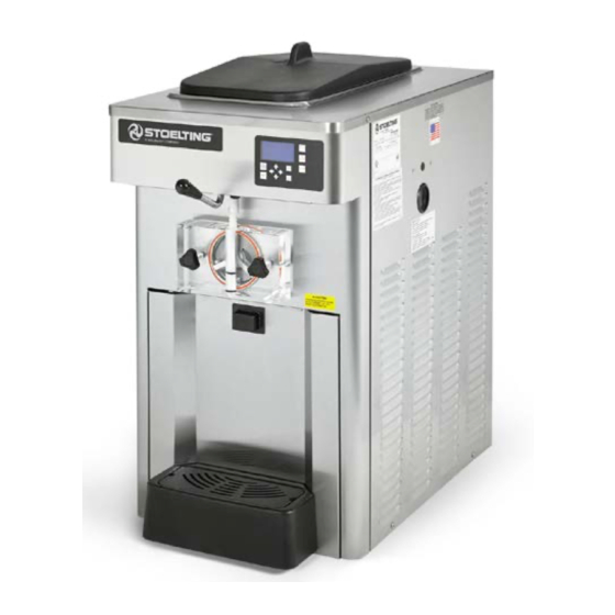
Section 1 - Description and Specifications DESCRIPTION The Stoelting O111-I2F counter-top machines are gravity fed. The machines are equipped with the IntelliTec2™ con- trol which provides a uniform product. The machines are designed to operate with almost any type of commercial soft serve or non-dairy mixes available, including: ice milk, ice cream, yogurt, and frozen dietary desserts. -
Page 8: Specifications
SPECIFICATIONS Model O111-I2F Dimensions Machine with crate width 19-3/4’’ (50,2 cm) 28’’ (71,1 cm) height 36-1/4’’ (92,1 cm) 40-1/4’’ (102,2 cm) depth 31-3/8’’ (79,7 cm) 35-1/4’’ (89,5 cm) Weight 385 lbs (174,6 kg) 400 lbs (181,4 kg) Electrical 1 Phase, 208-240 VAC, 60Hz 3 Phase, 208-240 VAC, 60Hz running amps 10A Air-Cooled / 11A Water-Cooled... -
Page 9: Section 2 - Installation Instructions
Section 2 - Installation Instructions SAFETY PRECAUTIONS A. TOOLS NEEDED • Level Do not attempt to operate the machine until the safety precautions and operating instructions in this manual are • Screwdrivers and wrenches read completely and are thoroughly understood. •... -
Page 10: Intellitec2™ Setup
In air cooled machines correct ventilation is required. 2.4 INTELLITEC2™ SETUP The right side of the machine is the air intake and Disassemble, clean, lubricate and assemble the left side is the discharge. Both sides must have 3” machine following the steps in Section 3. Train store clearance. - Page 11 After the password is accepted, use the arrows to C. SETTING TIME AND DATE move the cursor to the Modify Settings option and Press the right arrow button. press the SEL button. Then move the cursor to the Move the cursor to the Modify Settings option and User Preferences and press the SEL button.
- Page 12 Adjust the product consistency by increasing or decreasing the Consist Offset settings. These settings are under the Modify Settings - Basic Settings menu. Adjust the settings as follows: • If the product is too soft, increase the CutIn Consist Offset. •...
-
Page 13: Section 3 - Initial Set-Up & Installation
Section 3 - Initial Set-Up & Installation OPERATOR’S SAFETY PRECAUTIONS 3.2 OPERATING CONTROLS AND INDICATORS SAFE OPERATION IS NO ACCIDENT; observe these rules: Before operating the machine, it is required that the op- erator know the function of each operating control. Refer Know the machine. -
Page 14: Emptying The Freezing Cylinder
Press the Clean button. After about 5 minutes open the spigot to drain the mix. Press the Clean button to stop the auger. Fill the hopper with 2 gallons (8 liters) of cool tap water. Optional: Use detergent solution instead of tap water to make cleaning the parts easier after disassembly. -
Page 15: Cleaning Disassembled Parts
Remove all o-rings from parts by first wiping off the 3.5 CLEANING DISASSEMBLED PARTS lubricant using a clean towel. Then squeeze the Disassembled parts require complete cleaning, sanitizing o-ring upward to form a loop. Roll the o-ring out of and air drying before assembling. Local and state health the groove. -
Page 16: Sanitizing
NOTICE Place the front door assembly on the mounting studs and the push front door against the machine carefully. The United States Department of Agriculture and the Food and Drug Administration require that lubri- NOTE cants used on food processing equipment be certi- Make sure the pin of the front door do not touch the fied for this use. -
Page 17: Freeze Down And Operation
Install the carburetor. 3.8 FREEZE DOWN AND OPERATION NOTE Sanitize immediately before use. Do not twist the carburetor when installing. Fill the hopper with at least 2.5 gallons of mix. • Standard Carburetor: install with the air tube Place a container under the spigot and open the towards the front of the machine. -
Page 18: Mix Information
3.9 MIX INFORMATION Mix can vary considerably from one manufacturer to an- other. Differences in the amount of butterfat content and quantity and quality of other ingredients have a direct bearing on the finished frozen product. A change in ma- chine performance that cannot be explained by a technical problem may be related to the mix. -
Page 19: Section 4 - Maintenance And Adjustments
Section 4 - Maintenance and Adjustments CONDENSER CLEANING (AIR-COOLED This section is intended to provide maintenance personnel with a general understanding of the machine adjustments. MACHINES) It is recommended that any adjustments be made by a The condenser requires periodic cleaning. To clean, refer qualified person. -
Page 20: Extended Storage
4.3 EXTENDED STORAGE Refer to the following steps for storage of the machine over any long period of shutdown time: Thoroughly clean all parts that come in contact with mix with warm detergent water. Rinse in clear water and dry all parts. Do not sanitize. NOTE Do not let cleaning solution stand in the freezing cylinder or hopper during the shutdown period. -
Page 21: Section 5 - Troubleshooting
Section 5 - Troubleshooting ERROR CODES Error Code 3 - Run Time The Run Time Error (E3) occurs when the compressor When the machine experiences a problem, one of the runs continuously for an extended period. This error is following error codes is displayed on the control panel. generally caused by very low mix levels in the hopper or Each error code directs you to the system location of the from product breakdown. - Page 22 Error Code 6 - Hopper Sensor Error Code 10 - Auxiliary Sensor The Hopper Sensor Error (E6) indicates a failure of the hop- An Auxiliary Temperature Sensor Error (E10) occurs if the per sensor or that the sensor is out of range. If the control temperature sensor on the control board fails.
-
Page 23: Troubleshooting Machine
5.3 TROUBLESHOOTING MACHINE PROBLEM POSSIBLE CAUSE REMEDY Power to machine is off. Supply power to machine. Machine does not 2 Freeze-up (auger will not turn). 2 Turn machine off for 15 minutes, then restart. run. 3 Front door not in place. 3 Assemble front door in place. - Page 24 Operators Manual #513686 O111-I2F Model Machines...
-
Page 25: Section 6 - Replacement Parts
Section 6 - Replacement Parts DECALS & LUBRICATION Part Number Description Quantity C-1000-26C Decal - Made In USA 208135 Brush - 4” x 8” x 16” (Barrel) 208380 Brush - 1/4” x 3” x 14” 208401 Brush - 1” x 3” x 10” 208467 Brush - 3/8”... -
Page 26: Auger & Door
6.2 AUGER & DOOR 381804 381804 624678 624678 694255 694255 149003 149003 2177698 2177698 625133 625133 666786 666786 3156795-SV 3156795-SV 2205440 2205440 482019 482019 2187812 2187812 624598 624598 Part Number Description Quantity 381804 Auger Flight (Has 5) 482019 Knob - Front Door (Black) 624598-5 O-Ring - Spigot Body - Black (5 Pack) 624678-5... -
Page 27: Trays & Hopper Cover
6.3 TRAYS & HOPPER COVER 2204805 2204805 2205067 2205067 2203116 2203116 2204805 2204805 2205066 2205066 314477 314477 624677 624677 744608 744608 744284 744284 744283 744283 Part Number Description Quantity 215061 Plug - Bumper (Drip Tray) 232741 Cap - Rosette (6-Point Teardrop) (Translucent) 266076 Clip - Drip Tray 314477...
Need help?
Do you have a question about the Stoelting O111-I2F and is the answer not in the manual?
Questions and answers