Advertisement
Table of Contents
- 1 Introduction
- 2 Table of Contents
- 3 Instrument Components
- 4 Measurement Preparations
- 5 User Interface
- 6 Set of Characters
- 7 Operation
- 8 Check & Adjust
- 9 Error Messages
- 10 Operation Messages
- 11 Care and Transport
- 12 Safety Directions
- 13 Technical Data
- 14 International Limited Warranty, Software Licence Agreement
- 15 Index
- Download this manual
See also:
User Manual
Advertisement
Table of Contents

Related Manuals for GeoMax ZDL700


Summary of Contents for GeoMax ZDL700
- Page 1 GeoMax ZDL700 User Manual Version 1.0...
-
Page 2: Introduction
Purchase ZDL700 All instructions required in order to operate the Congratulations on the purchase of a new GeoMax electronic User product to a basic level are contained in this User level. It is designed to make levelling works easier and quicker on Manual Manual. -
Page 3: Table Of Contents
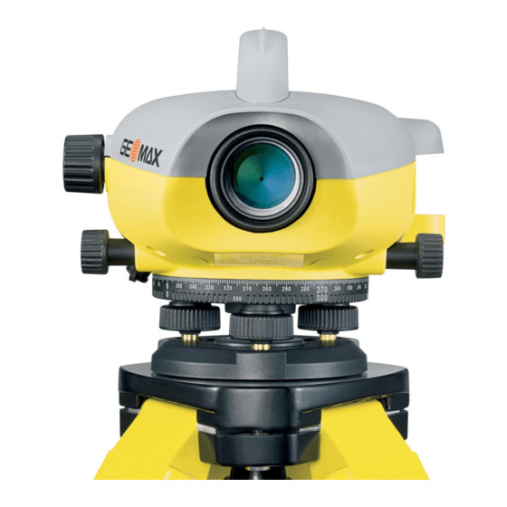
Circular level h) LCD display Agreement ..............29 d) Gunsight i) Base plate e) Focusing knob j) Levelling foot- 14. Index ................30 screw Container Contents ZDL700, allen key, user manual, strap, CD-ROM, RS232 data transfer cable. Instrument Components ZDL700 |... -
Page 4: Measurement Preparations
ZDL700 | Accessories Target Image Focusing Tripod, GeoMax telescopic aluminium staff, GeoMax 1 section, Use the gunsight to aim the objective lens at the staff. Turn the fibre glass staff. (Optional: sunshade, 4 rechargeable batteries and horizontal fine motion screw until the staff is nearly centered in the charger) field of view and then turn the focusing knob to focus on the staff. -
Page 5: User Interface
Press and hold for 3 seconds to start and stop tracking measure- ment / timer measurement c) Height / Alternating between Height and Cursor up (in Menu / Settings mode), Switch between intermediate Distance Distance display sight I and foresight F in line leveling program BIF User Interface ZDL700 |... - Page 6 User Interface ZDL700 | Symbol 1 level functions level functions d) dH Height Difference and Elevation meas- Cursor down (in Menu / Settings mode) urement e) MENU Activation and Selection of settings ENTER key for confirmation purpose f) Backlight LCD backlight illumination...
- Page 7 Elevation Menu Setting Menus Selections (sub-selections) Descriptions 1. Program Line Levelling (BIF, BF, BFFB) Select line levelling method. Sighting and measurement sequence in line levelling is indicated with highlighted 'alphabet' of the respective line levelling icons. User Interface ZDL700 |...
- Page 8 User Interface ZDL700 | Menus Selections (sub-selections) Descriptions 2. Intermediate ON / OFF Enable / disable Intermediate Sight in BIF line levelling. Sight 3. Input PtID Input user point ID. 4. Input BM Input Reference Benchmark elevation. 5. Data Manager View Data Viewing recorded data / deleting of a recorded data by pressing ENTER key.
- Page 9 Timer Input measurement time interval 00 hr: 00 min (applicable to Ht / Dist applica- tion only). Press height / distance or dH or backlight or menu key. A message "stop Tracking" will be displayed. User Interface ZDL700 |...
-
Page 10: Set Of Characters
Set of Characters ZDL700 | 5. Set of Characters 6. Operation Height and Distance measurement (electronic) Benchmark Elevation (BM), Example of an electronic measurement: numeric input consists of 0 ~ 9, space, decimal, Ft in 1/16 inch separator, the "+" and "-" signs. - Page 11 Standby Mode progress height and distance Step Description Press to switch on the instrument, GeoMax logo is displayed follow by the default meas- urement standby mode. Aim at staff and focus. Lightly trigger the measurement key to activate measurement. Height and distance measurement is displayed.
- Page 12 Operation ZDL700 | 6.2 Height Difference and Reduced Level Measurement (internal Memory not active) Step Key/Screen Description MEAS Press key to start height difference and reduced level function. 100.038m : >>>> 1.235 A message "Meas. Reference" with input Meas Reference 5.68...
- Page 13 Go to menu set "Interme- Foresight measurement Measure to backsight of diate sight with prompt diate Sight" to OFF OR displayed with prompt next change point with message press Height & Distance message prompt message key, measure to foresight Operation ZDL700 |...
- Page 14 Operation ZDL700 | 6.4 BF Line Levelling Measurement Step Key/Screen Description Step Key/Screen Description Initialize the BIF method. Initialize the BF method Initiate measurement to Benchmark. Initiate measurement to Benchmark Backsight measurement displayed. Backsight measurement displayed. To start 'Intermediate sight' measure- Measure to the foresight staff.
- Page 15 BFFB line levelling method. Measurement to foresight. Foresight measurement displayed. Measure to the foresight staff (second sighting). Foresight (second sighting) measure- ment displayed. Measure to the backsight staff (second sighting). Backsight (second sighting) measure- ment displayed. Operation ZDL700 |...
-
Page 16: Check & Adjust
Communication press ENTER key to accept. Communications parameters of the RS232 interface for data Now shift the ZDL700 towards staff A and set it up at about 3 m to transfer from instrument to computer / external device. staff A. - Page 17 Level instrument. Check collimation. Turn instrument by 180°. If the collimation error exceeds 3 mm over 60 m distance, the colli- mation needs to be adjusted. Center bubble if it extends beyond the centering circle. Check & Adjust ZDL700 |...
-
Page 18: Error Messages
Error Messages ZDL700 | 8. Error Messages Error message Counter measure / causes System Error, Contact Hardware faults or file errors or adjustment errors or setting errors rendering instrument not working Services ! properly. E100 Low Battery ! Change to new or freshly charged batteries. -
Page 19: Operation Messages
Start Tracking! Tracking mode starts. Stop Tracking! Tracking mode stops. Tracking Hold! Press measure key for 3 seconds to restart tracking mode. Tracking will hold after 10 unsuccessful meas- urements. Abort Measurement! Current measuring process is terminated. Operation Messages ZDL700 |... - Page 20 Operation Messages ZDL700 | Operation message Counter measure / remark Downloading Data! Downloading of data from the internal memory to an external device is in progress. Download Completed! System has successfully downloaded the internal memory data to an external device.
-
Page 21: Care And Transport
When transporting the product by rail, air or sea, always use the • Use only a clean, soft, lint-free cloth for cleaning. If necessary, complete original GeoMax packaging, transport container and moisten the cloth with water or pure alcohol. Do not use other cardboard box, or its equivalent, to protect against shock and liquids;... -
Page 22: Safety Directions
• Removal of hazard notices. Manufacturer of the product • Opening the product using tools, for example screwdriver, GeoMax AG, CH 9443 Widnau, hereinafter referred to as unless this is specifically permitted for certain functions. GeoMax, is responsible for supplying the product, including the •... - Page 23 • To inform GeoMax immediately if the product and the applica- Precautions: tion becomes unsafe. Keep at a safe distance from electrical installations. If it is essential...
- Page 24 Adhere to the instructions given by the computer manufacturer Precautions: with regard to field use in conjunction with GeoMax products. Before shipping the product or disposing of it, discharge the batteries by running the product until they are flat.
- Page 25 Precautions: Product specific treatment and waste management information can be downloaded from the GeoMax home page at http:// Protect the batteries from mechanical influences and high ambient www.geomax-positioning.com or received from your GeoMax temperatures. Do not drop or immerse batteries into fluids.
- Page 26 Use only the equipment and accessories recommended by This equipment has been tested and found to comply with GeoMax. When combined with the product, they meet the strict the limits for a Class B digital device, pursuant to part 15 of the requirements stipulated by the guidelines and standards.
- Page 27 Labelling Safety Directions ZDL700 |...
-
Page 28: Technical Data
For communication to PC / data collector via RS232 data transfer cable. Internal Memory Storage Capacity: up to 2000 points. Data Transfer Programs To PC via RS232 using GeoMax PC-Tools and HyperTerminal via RS232 on PC, using a Windows® application Battery Power AA dry cells 4 x 1.5 V... - Page 29 • Protection against water, dust and sand: IP55 (IEC 60529) tions • Protection against Humidity: Up to 95% humidity no condensation. The effects of condensation are to be effectively counteracted by periodically drying out the product. Technical Data ZDL700 |...
-
Page 30: International Limited Warranty, Software Licence Agreement
This product contains software that is preinstalled on the product, or that is supplied to you on a data carrier medium, or that can be downloaded by you online pursuant to prior authorization from GeoMax AG. Such software is protected by copyright and other... -
Page 31: Index
14. Index laws and its use is defined and regulated by the GeoMax Software Licence Agreement, which covers aspects such as, but not limited to, Scope of the Licence, Warranty, Intellectual Property Rights, Limitation of Liability, Exclusion of other Assurances, Governing Accessories ................ - Page 32 Index ZDL700 | Cleaning and Drying .............. 20 Input BM ...................7 Components ................2 Input PtID ..................7 Container Contents ..............2 Intermediate Sight ..............7 Contrast ................... 8 Inverse Staff ................7 Data Display Symbols .............. 6 Language ..................8 Data Manager ................7 LCD display ................2...
- Page 33 Settings ..................8 Set-up Instrument Eyepiece Adjustment ............3 Levelling ................3 Target Image Focusing ............ 3 Storage .................. 20 Symbols ................... 1 Tilt Warning ................8 Timer ..................8 Timer Measurement .............. 15 Transport ................20 Index ZDL700 |...
- Page 34 GeoMax ZDL700 Series Copyright GeoMax AG, Widnau Switzerland 2009 Survey Instrument Sales SurveyInstrumentSales.com sales@SurveyInstrumentSales.com...
Need help?
Do you have a question about the ZDL700 and is the answer not in the manual?
Questions and answers