Table of Contents
Advertisement
40MAHB
Ductless Split Unit System
Sizes 9, 12, 18, 24, 30 and 36
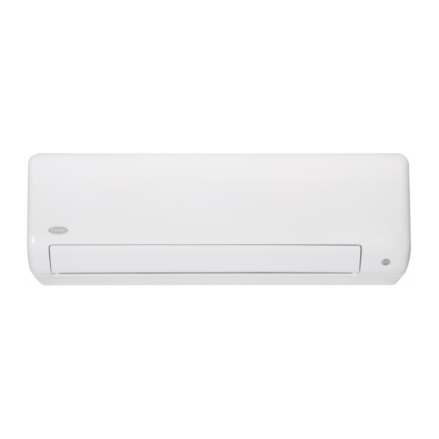
Fig. 1 - Sizes 09K - 36K
NOTE: Read the entire instruction manual before starting the
installation.
Images are for illustration purposes only. Actual models
may differ slightly.
Installation Instructions
Specifications subject to change without notice.
TABLE OF CONTENTS
SAFETY CONSIDERATIONS........................................................2
ACCESSORIES................................................................................3
PARTS..............................................................................................4
SYSTEM REQUIREMENTS...........................................................6
WIRING ...........................................................................................6
DIMENSIONS..................................................................................7
CLEARANCES ................................................................................7
PRIOR TO INSTALLATION ..........................................................8
Step 1 - Check Equipment ................................................................8
Step 2 - Select the Installation Location ...........................................8
Step 3 - Attach the Mounting Plate to the Wall................................9
Step 4 - Drill Wall Holes for Connective Piping..............................9
Step 4 - Prepare Refrigerant Piping ..................................................10
Step 5 - Connect the Drain Hose ......................................................11
Step 6 - Connect the Signal and Power Cables.................................12
Step 7 - Wrap Piping and Cables......................................................13
Step 8 - Mount the Indoor Unit.........................................................13
ELECTRICAL DATA......................................................................14
CONNECTION DIAGRAMS ..........................................................14
WIRELESS REMOTE CONTROL INSTALLATION ...................16
WIRED REMOTE CONTROL INSTALLATION..........................17
START-UP .......................................................................................17
TROUBLESHOOTING ...................................................................19
DUCTLESS START-UP CHECKLIST - Single Zone ....................21
PAGE
Advertisement
Table of Contents

Subscribe to Our Youtube Channel
Related Manuals for Carrier 40MAHB Series


Summary of Contents for Carrier 40MAHB Series
-
Page 1: Table Of Contents
40MAHB Ductless Split Unit System Sizes 9, 12, 18, 24, 30 and 36 Installation Instructions TABLE OF CONTENTS PAGE SAFETY CONSIDERATIONS............2 ACCESSORIES................3 PARTS....................4 SYSTEM REQUIREMENTS............6 WIRING ...................6 DIMENSIONS..................7 CLEARANCES ................7 PRIOR TO INSTALLATION ............8 Step 1 - Check Equipment ..............8 Step 2 - Select the Installation Location ...........8 Fig. -
Page 2: Safety Considerations
SAFETY CONSIDERATIONS WARNING Improper installation, adjustment, alteration, service, maintenance, or use can cause explosion, fire, electrical shock, or other conditions which may cause death, personal injury or property damage. Consult a qualified ELECTRICAL SHOCK HAZARD installer, service agency, or your distributor or branch for information or Failure to follow this warning could result in personal injury or assistance. -
Page 3: Accessories
ACCESSORIES The system is shipped with the following accessories (see Table 1). Use Table 2 — Accessories all of the installation parts and accessories to install the system. Improper NAME SHAPE QUANTITY (PC) installation may result in water leakage, electrical shock and fire, or cause 1/4in(Φ... -
Page 4: Parts
PARTS Boost Fig. 2 — Parts NOTE: Illustrations in this manual are for reference only. The actual shape of the indoor unit and parts may differ slightly. 1. Wall Mounting Plate NOTES: 2. Front Panel - If the outdoor unit is higher than the indoor unit, prevent 3. - Page 5 PARTS (CONT) NOTE: The installation must be performed in accordance with the requirement of local and national standards. The installation may differ slightly in some areas. Air Filter (pull up to remove) Front Panel Remote Control Boost Louver Remote Control Holder ECO intelligent eye (some units) (some units)
-
Page 6: System Requirements
SYSTEM REQUIREMENTS Allow sufficient space for airflow and unit service. Fig. 5 — on page 7 for the minimum required distances between the unit and walls or ceilings. Table 4 — Indoor Unit Pipe Sizes UNIT SIZES (115V) (208/230V) (208/230V) (208/230V) (208/230V) (208/230V) -
Page 7: Dimensions
DIMENSIONS Fig. 4 — Dimensions Table 5 — Dimensions HIGH WALL UNIT SIZE (Voltage) (115V) (208/230V) (208/230V) (208/230V) (208/230V) (208/230V) (208/230V) DIMENSIONS Height (H) In (mm) 11.61 (295) 11.61 (295) 11.61 (295) 12.56 (319) 14.57 (370) 14.57 (370) 14.57 (370) Width (W) In (mm) 31.3 (795) -
Page 8: Prior To Installation
PRIOR TO INSTALLATION Step 2 - Select the Installation Location Before installing the indoor unit, ensure the compatibility with the outdoor unit using the product data as a reference. It is also necessary to confirm the proper application of the equipment and to perform a Before installing the indoor unit, choose an appropriate location. -
Page 9: Step 3 - Attach The Mounting Plate To The Wall
Step 3 - Attach the Mounting Plate to the Step 4 - Drill Wall Holes for Connective Piping Wall 1. Determine the location of the wall hole based on the position of the mounting plate. Refer to the Mounting Plate Dimensions. Use the following steps to attach the mounting plate to the wall. -
Page 10: Step 4 - Prepare Refrigerant Piping
Step 4 - Prepare Refrigerant Piping 16.2in(411mm) The refrigerant piping is inside an insulating sleeve attached to the 9.7in(246mm) 9.1in (230mm) back of the unit. The installer must prepare the piping before passing it through the hole in the wall. Indoor unit outline 1. -
Page 11: Step 5 - Connect The Drain Hose
Step 5 - Connect the Drain Hose CAUTION By default, the drain hose is attached to the left-hand side of the unit (when you are facing the back of the unit). However, it can also be All wiring must comply with local and national electrical codes, attached to the right-hand side. -
Page 12: Step 6 - Connect The Signal And Power Cables
Step 6 - Connect the Signal and Power 3. Unscrew the cable clamp, below the terminal block, and place it to the side. Cables 4. Facing the back of the unit, remove the plastic panel on the bottom left-hand side. All wires must be sized per NEC (National Electrical Code) or CEC 5. -
Page 13: Step 7 - Wrap Piping And Cables
Step 7 - Wrap Piping and Cables Step 8 - Mount the Indoor Unit Before passing the piping, drain hose, and the signal cable through the If new connected piping to the outdoor unit has been installed, wall hole, bundle them together to save space, protect them, and complete the following steps: insulate them (not applicable in North America). -
Page 14: Electrical Data
ELECTRICAL DATA Table 6 — Electrical Data HIGH WALL INDOOR UNITS HP (115V) (208/230V) (208/230V) (208/230V) (208/230V) (208/230V) (208/230V) Running Current 0.467 0.182 0.182 0.11 0.364 0.364 0.364 Power Consumption Power Factor 81.54 65.9 95.2 70.2 96.5 98.7 CONNECTION DIAGRAMS Fig. - Page 15 INSTALL ALL POWER, Remove the flare nuts attached to the indoor and outdoor units. INTERCONNECTING WIRING, AND PIPING Install the correct size flare nut onto the tubing and make TO THE INDOOR UNIT the flare connection. Refer to Table 7 for the flare nut spaces.
-
Page 16: Wireless Remote Control Installation
FINAL TUBING CHECK WIRELESS REMOTE CONTROL INSTALLATION IMPORTANT: Ensure the certain factory tubing on the indoor unit has not shifted during shipment. Ensure the tubes are not rubbing against each other or any sheet metal. Pay close attention to feeder tubes and ensure the wire ties on the feeder tubes are secure and tight. -
Page 17: Wired Remote Control Installation
WIRED REMOTE CONTROL START-UP INSTALLATION Test Operation The wired remote controller comes with the following items: Perform a test operation after completing a gas leak and electrical • A set of installation instructions and owner's manuals safety check (see Fig. 35). •... - Page 18 SYSTEM CHECKS INDOOR UNIT 1. Do all remote control buttons function properly? 1. Conceal the tubing where possible. 2. Do the display panel lights work properly? 2. Ensure the drain tube slopes downward along its entire length. 3. Does the air deflection louver function properly? 3.
-
Page 19: Troubleshooting
TROUBLESHOOTING For ease of service, the systems are equipped with diagnostic code display LEDs on both the indoor and outdoor units. The indoor diagnostic display is a combination of flashing LEDs on the display panel or the front of the unit. Some indoor units display error codes specifying failure modes in the outdoor units. - Page 20 INDOOR UNIT FUNCTIONAL CODES Table 10 — Indoor Unit Functional Codes DISPLAY DESCRIPTION Defrost Self clean Filter cleaning reminder Active Clean (*model dependent) Filter replacement reminder Heating in room temperature under 8°C Forced cooling AP mode of WIFI connection Remote switched off Remote or Wire controller Lock Time On Time Off...
-
Page 21: Ductless Start-Up Checklist - Single Zone
DUCTLESS START-UP CHECKLIST - Single Zone Installation Data Site Address:_______________________________________________________________________________________________________ City:________________________________________________________ State:___________ Zip Code:__________________ Installing Contractor:______________________________________________________ Contractor Contact #: ( ) _____-___________ Job Name:_______________________________________________________________ Start-up Date:_____________________________ Distributor:_______________________________________________________________ System Details UNITS MODEL NO. SERIAL NO. CONTROLLER OUTDOOR UNIT INDOOR UNIT A Are the outdoor unit and indoor unit compatible? YES:______ NO:______ Wiring Electrical... - Page 22 __________________________________________________________________________________________________________________ __________________________________________________________________________________________________________________ __________________________________________________________________________________________________________________ Copyright 2020 Carrier Corp D 3300 Riverwood Parkway Atlanta GA, 30339 Edition Date: 12/20 Catalog No. 40MAHB-01SI Manufacturer reserves the right to discontinue, or change at any time, specifications or designs without notice and without incurring obligations.
Need help?
Do you have a question about the 40MAHB Series and is the answer not in the manual?
Questions and answers