Table of Contents
Advertisement
Quick Links
Advertisement
Table of Contents

Related Manuals for HARVEY GYROAIR G-800


Summary of Contents for HARVEY GYROAIR G-800
- Page 1 Revision A : 2021-02-05 298005512...
-
Page 2: Table Of Contents
Index of Contents 1. Foreword..............................2 2. Machine Description..........................3 2.1 Feature Identification........................3 2.2 Specification...........................4 2.3 Electrical Power Requirement.....................5 3. Safety Regulations..........................7 3.1 General Safety Instructions......................7 3.2 Specific Safety Instructions for the Dust Processor..............8 4. Installation of the Machine........................9 4.1 Transportation of Machine......................9 4.2 Positioning the Machine ......................10 4.3 Assembly............................ -
Page 3: Foreword
We maintain the right to modify specifications, designs, operation and maintenance instructions without advance notice. We offer a two-year warranty based on the purchase date. Defective parts will be repaired or replaced by Harvey at no charge. We do not offer the warranty service for the following reasons: Misuse ... -
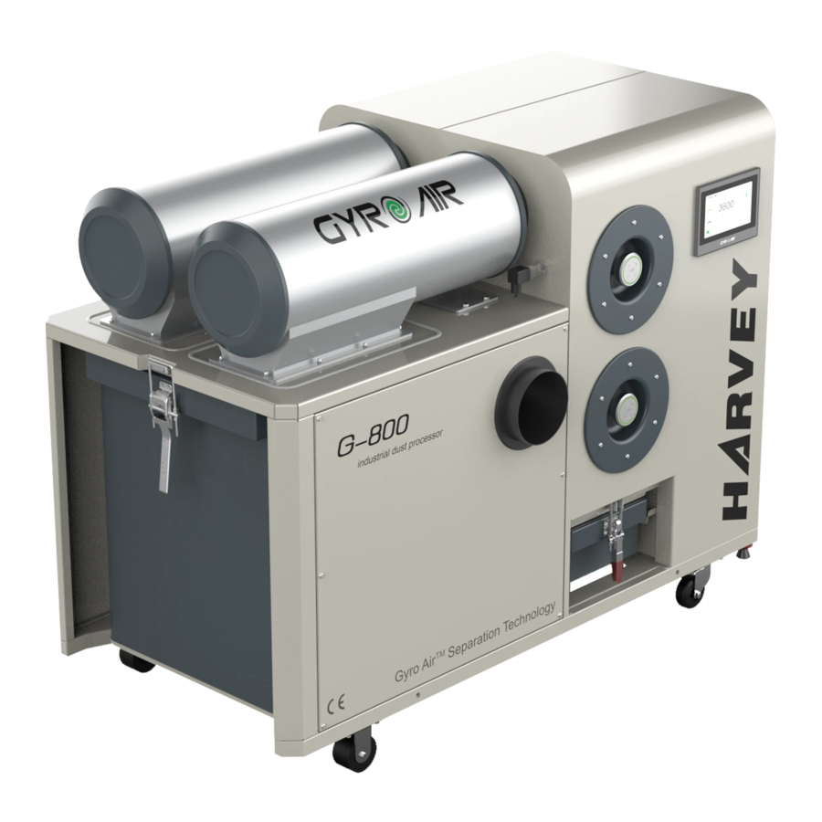
Page 4: Machine Description
2. Machine Description This product uses the Gyro Air dust processing technology, which effectively separates the dust from the air flow before the filter. This machine has the following features: Reduces filter clogging: The Gyro Air technology efficiently separates 99.7% of the dust from the air flow BEFORE the filter, providing the benefit of a lower capacity load on the filter and a longer filter life. -
Page 5: Specification
2.2 Specification G-800 Model Metric Imperial Electrical Power Requirement 200-240V 50Hz 1-Phase 200-240V 60Hz 1-Phase Breaker Size Inverter Type INOVANCE MS300 INOVANCE MS300 Motor Type TEFC Induction TEFC Induction Power 2.2kW 2.2kW(3HP) Voltage/Phase 220V/3-Phase 220V/3-Phase Rated Amps 8.2A 8.2A Speed 2400-4200rpm Variable Dimensions &... -
Page 6: Electrical Power Requirement
2.3 Electrical Power Requirement Power requirement: AC220V, 1-phase Breaker Size: The machine needs no further electrical installation. For the North American market, the equipment comes with the cable equipped with a plug (6-20P). For the European market, the machine is equipped with a plug in European Standard. The input power supply of the machine is 1-phase, AC220V. - Page 7 2.3.3 Electrical diagram (Fig. 2) Fig. 2...
-
Page 8: Safety Regulations
3. Safety Regulations 3.1 General Safety Instructions 1. Read and understand the owner’s manual and labels affixed to the machine. Learn its application and limitations as well as its specific potential hazards. 2. The power supply socket or terminals need reliable grounding. 3. -
Page 9: Specific Safety Instructions For The Dust Processor
3.2 Specific Safety Instructions for Dust Processor 1. CLEAN ENVIRONMENT Once you are ready to commence work, remove any tools, objects or items that could inadvertently get ‘sucked up’ by the machine and place them safely out of the way. 2. -
Page 10: Installation Of The Machine
4. Installation of the machine This machine needs little-to-no assembly. It can almost be used directly out of the box. 4.1 Transportation of machine 4.1.1 Transportation and storage The machine should be transported and stored in -25~55°C (-77~131°F) ambient temperature. Take care not to allow the machine to be exposed to rain or damage to the packing during transportation and storage. -
Page 11: Positioning The Machine
4.2 Positioning the machine (Fig. 4) Fig. 4 The machine should be placed at least 50cm (18 inches) away from the wall to ensure that the motor heat dissipation is adequate. 4.3 Assembly 4.3.1 Unpacking Open shipping container and check for shipping damage. Report any damage immediately to your distributor and shipping agent. -
Page 12: Connection
4.3.3 Connection Use flexible hose or solid pipe to connect the inlet with the dust source. Plastic pipe, such as Polypropylene or Polyvinyl Chloride, can be used as long as it’s been determined and confirmed that the dust is not an explosion hazard. This machine does not contain dust collection hose(s) due to the dust source differences. -
Page 13: Air Supply
4.3.5 Air Supply (compressed air) Make sure the switch is in the “OFF” position before connecting to the compressor to avoid an unexpected start. Air pressure requirement should be at least 0.8MPa (115psi). As shown in Fig. 8, follow the instruction below: Inspect the oil water separator pressure valve. -
Page 14: Function And Operation
5. Function and Operation. 5.1 Touch Screen Operation Instruction(Fig. 10) When the power is connected, the touch screen will light up and the main interface will display (as shown in Fig.10).The touch screen has four sections: A: Running status display area. B: Alarm information display. - Page 15 5.1.2 Alarm information display area B(Fig. 10-2) Fig.10-2 There is no display in normal status. B1: Converter error code display. B2: Shows the alarm of communication failure between touch screen and converter. 5.1.3 Operation and control area C(Fig. 10-3) Fig.10-3 The operation control area C has three states, as shown in Figure 10-3.
- Page 16 C3: Re-link C3 is the re-link button, it shows light colour in normal state. When the start/stop mode of the machine is set up to the linkage mode, the manual start/stop operation (including the remote control) will change the mode into manual mode on its own. Only the manual start/stop operation is permitted at this time.
- Page 17 D3: Running mode set up(Fig. 10-6) The machine can run in Speed Adjustment mode or Flow Cruise mode. Select the desired running mode by clicking the button “Speed/Power” (Fig.10-6), then click the D1 button back to main interface. If selecting the Speed Adjustment mode, click the data input area indicated by the arrow to enter the motor speed.
- Page 18 D5: Set up the dust cleaning parameter and mode(Fig. 10-8) Fig.10-8 Set up the dust cleaning parameter and select the dust cleaning mode by clicking the “Cleaning Set” button (Fig.10-8). Set up the dust cleaning parameter: Click the input area of the filter pressure difference threshold value to enter the set pressure difference threshold parameter (The system default pressure threshold value is 1000 pa, the recommended input range: 500-2000).After entering and confirming, click the D1 button back to main interface.
-
Page 19: Instructions For Remote Control
5.2 Instructions for Remote Control The Remote Control as supplied can be used to start and stop the dust processor. The remote control connects to the dust processor through Bluetooth, and the effective control distance is up to 50 meters. When using the remote control, the operator does not need to aim the remote control to the dust processor. -
Page 20: Pulse Parameters
5.4 Pulse P arameters Parameter name Parameter Value Number of pulses Period cycle 300 seconds Pulse period 10 seconds Width of pulse 0.12 seconds The parameters above have been set in factory and can not be changed. Parameters description: Number of pulses: the number of pulse magnetic valves equipped on the machine. Period cycle: the time between the pulse magnetic valves opening and closing. -
Page 21: Maintenance
6. Maintenance Power off the machine before cleaning. Do not clean, repair or maintain the machine until all moving parts have stopped to avoid serious injuries. Disconnect the air supply before cleaning, repair or maintenance. 6.1 Cleaning Dust Bin (Fig. 13) The dust bin must be cleaned when the dust bin is 2/3 full for non-metal material. -
Page 22: Troubleshooting
7. Troubleshooting 7.1 Dust Bin Full & Pressure Drop Alarm When the alarms occur, the Start/Stop button will become yellow: The machine will stop automatically 15 minutes after the dust bin full alarm occurs. When the filter clogging alarm occurs, the machine will be cleaned automatically in running state. -
Page 23: Parts List
8. Parts List Frame Assembly Exploded View DESCRIPTION DESCRIPTION Frame welding assembly Foot Locking hook Swivel caster Button HD screw M6x12 Rigid caster Set screw M4x10 Air inlet-1 Heat-sink window EVA gland Photo switch Air inlet-2 Electrical box cover Rubber retainer Rubber seal strip 1.5m Front cover... - Page 24 Cabinet Assembly Exploded View...
- Page 25 Cabinet Assembly Parts List REF DESCRIPTION REF DESCRIPTION 201 Cabinet 237 Clean Air Co m ponent 202 Dust board 238 Brass ball valve 203 Flat washer 6 240 Strain relief PG13.5 204 Spring washer 6 241 Switch 205 Cap screw M6x12 242 Button HD screw M6x30 206 Cap screw M6x16 243 Switch bracket...
- Page 26 Filter Assembly Exploded View DESCRIPTION DESCRIPTION Filter Lock handle Gasket for end cover Circlip for shaft 30 Filter end cover Green decorative circle Button HD screw M6x12 Gasket for filter Teflon gasket...
- Page 27 Blower group Exploded View DESCRIPTION DESCRIPTION Hex bolt M12x40 Cap screw M6x16 Spring washer 12 Spring washer 6 Flat big washer 12 Flat washer 6 Shock pad Hex bolt M8x20 The fan casing Spring washer 8 Sound insulation damper Flat big washer 8 Motor...
- Page 28 Dust Bin Assembly Exploded View DESCRIPTION DESCRIPTION Rubber seal strip Spring washer 6 Set screw M5x6 Flat washer 6 Dust bin Button HD screw M6x16 Lock bracket Button HD screw M6x16(Nickel) Flat washer 8 Lock nut M6 Spring washer 8 Lock pin Hex bolt M8x16 U type bolt...
- Page 29 Separation Assembly Exploded View DESCRIPTION Horizontal left-handed separator Gasket for separator adapter Separator adapter Hex bolt M6x20 Silicone Spring washer 6 Flat washer 6 Horizontal right-handed separator EVA gland Button HD screw M6x16 Cap nut M6 Separate core welding assembly Hex bolt M8x20 Spring washer 8 Flat washer 8...
- Page 30 Electric box Exploded View REF DESCRIPTION REF DESCRIPTION 701 Philips screw M6x12 717 Cable 1*2C 702 Spring washer 6 718 Strain relief PG13.5 703 Flat washer 6 719 Nut M6 704 Electrical installation plate 720 Double-side tap 705 Frequency converter V20 721 Wireless receiving module 706 Switching Power Supply 722 Wireless receiver module shell...
- Page 31 Y Adapter Exploded View DESCRIPTION DESCRIPTION Silicone 150mm Adapter 4"-2" Y type inlet Seal cover Adapter 4" Chain...
-
Page 32: Declaration Of Conformity
9. Declaration of Conformity... - Page 33 Dust Processor Harvey Industries Co., Ltd 68-10 Suyuan Avenue, Jiangning District, Nanjing 211100, China www.harveymachinery.com Harvey Industries International Inc. 10830 Ada Ave. Montclair, CA. 91763 TEL: 1-800-253-3332 E-mail: info@harveywoodworking.com...
Need help?
Do you have a question about the GYROAIR G-800 and is the answer not in the manual?
Questions and answers