
Related Manuals for HARVEY Axminster Trade AT220TSM


Summary of Contents for HARVEY Axminster Trade AT220TSM
- Page 1 Code 104478 Original Instructions AT220TSM CNC Tilting Spindle Moulder AT&M: 02/07/2019 BOOK REF : 007288...
-
Page 3: Table Of Contents
Contents Foreword Warranty Information Machine Description Feature Identification Intended Use Dimensions and weights Electrical Power Requirements Noise Technical Parameters Safety Regulations General Safety Instructions Specific Safety Instructions for Shaper Residual Risks Safety Equipment Safety Labels on the Machine Safety Devices Installation of the machine Transportation of the Machine Unpacking... -
Page 4: Foreword
1. Foreword This manual was conceived at the manufacturer and is an indivisible part of the delivery enclosed with the machine. It contains basic information for qualified operating staff and describes the surroundings and using ways of the machine for those it is indented. It contains also all necessary information for a correct and safe operating. -
Page 5: Machine Description
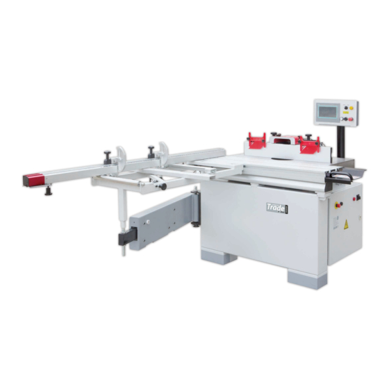
3. Machine Description 3.1 Feature Identification Cabinet Crosscut table Crosscut Fence Sliding table Guard Control panel Table Electrical box Fig.1 3.2 Intended Use 1. Purpose of the Machine The machine enables semi-finished products made of wood or materials based on wood to be milled with a spindle The machine is designed for operation performed by one worker only. -
Page 6: Electrical Power Requirements
3.4 Electrical Power Requirements List of the motor usage & pre-wired voltage Motor(kW) Voltage(V) Freq.(Hz) Nominal current (A) Pre-wired Cords 380-415V 50(60) 380-415V/3PH The input power supply of the machine is 3/N/PE, AC400V. The steady-state AC power supply is 0.9~1.1 times of the rated value. Frequency 0.99~1.01 times of rated frequency ( 50 Hz , continuous working) 0.98~1.02 times of rated frequency ( 50 Hz, short period working) -
Page 7: Technical Parameters
3.6 Technical Parameters Models E-305S Power Source 380-415V Three Phase Motor Electrical Rated Current Frequency 50/60Hz Table Height 890mm Main Table Size 1000 x 500mm Sliding Table Size 310 x1250mm Spindle Size φ35mm Insert Opening 65mm / 110mm / 146mm / 225mm Max. -
Page 8: Safety Regulations
4. Safety Regulations 4.1 General Safety Instructions 1. KNOW YOUR MACHINE. Read and understand the owner manual and labels affixed to the machine. Learn its application and limitations as well as its specific potential hazards; 2. GROUND THE MACHINE. In the event of the electrical short, grounding reduces the risk of electrical short; 3. -
Page 9: Specific Safety Instructions For Shaper
4.2 Specific Safety Instructions for Shaper 1. Serious personal injury may occur if normal safety precautions are overlooked or ignored. Accidents are frequently caused by lack of familiarity or failure to pay attention. Obtain advice from supervisor, instructor, or another qualified individual who is familiar with this machine and its operations. -
Page 10: Residual Risks
29. Fit the tooling to the machine to operate in the correct direction of rotation. Avoid injury when on use of tool carriers and handling tools. 30. Don't misuse, foreseeable misuse includes, e.g. feeding small work-pieces without safety appliance, mounting of a saw blade on the arbor instead of milling tools and feeding work-pieces in the same direction as of the running tool (climb cutting). -
Page 11: Safety Labels On The Machine
4.5 Safety Labels on the Machine Here below you will find the warning labels that are attached to the machine and illustrated in the instruction.(see Fig.5 Fig.5 Warning for residual risks (Fig.5-1) Fig.5-1 Fig.5-2 2. Specific Safety Instructions for Shaper. (Fig.5-2) 3. - Page 12 5. Warning for the choice of tools & speed. (Fig.5-5) Fig.5-5 6. Warning for the cutter rotation direction. (Fig.5-6) Fig.5-6 7. Warning for the fence using. (Fig.5-7) Fig.5-7 - 1 0 -...
-
Page 13: Safety Devices
4.6 Safety Devices Every time, before you operate the machine, you must check if the Disconnect switch, Emergent stop buttons, Interlocking switches is in order. When you set up, operate or service the machine , you must pay high attention to avoid the potential dangers. -
Page 14: Installation Of The Machine
5. Installation of the Machine 5.1 Transportation of Machines 5.1.1 Transportation and storage This machine has been well packaged and rust preventive measures have been taken at the factory. Care should still be taken to insure that no damage comes from rough handling while moving. -
Page 15: Unpacking
5.2 Unpacking Your machine was carefully packaged for safe transportation. Remove the packaging materials from around your machine and inspect it. If you discover that the machine is damaged, please immediately call Customer Service for advice. Save the containers and all packing materials for possible inspection by the carrier or its agent. -
Page 16: Installation
5.4 Installation 5.4.1 Positioning the base unit This unit is very heavy, serious personal injury may happen if safe moving methods are no followed! To be safe, you need assistance and power equipment when moving the shipping crate and the machine! Do not connect machine to electricity before installation is completed! Main base is mounted at the wooden pallet with three bolts, take out these bolts, separate the main base from the wooden pallet and move the main base to suitable place. -
Page 17: Cross-Cut Table Installation
5.4.3 Cross-cut table installation a. Slide the crosscut table into the T-slot on the side of the sliding table. b. Align the screw shaft (B) on the swing arm to the hole on the bottom of crosscut table support, and adjust the screws (C) and (D) to keep the surface of the crosscut table parallel to the surface of the sliding table, then tighten the screws (C) and (D). -
Page 18: Back Cover Installation
2. Install and lock the touch screen by turning the locking knob, as shown in Fig.20, 3. Plug the ports "A", "B", "C" and "D" into the corresponding sockets, as Fig.21 Fig.21 Fig.22 5.4.5. Back cover installation Slide the back cover onto the hinges which are pointed in , then lock the door with the Fig.22 screws on the other side. -
Page 19: Electrical Installation
5.4.7 Electrical installation Wiring should only be done by professional electricians. All wirings in the cabinets should be protected against the direct contact and at least meet the standard of IP2X when finishing electrical installation. All the exposed conductive parts should be connected to the protective bonding circuit. Close and lock the door of cabinet, take off the keys and keep them well stored after finishing installation. - Page 20 ELECTRICAL CONNECTIONS - 1 8 -...
-
Page 21: Adjustment
6. Adjustment Before operation, the machine should be carefully adjusted for best performance. 6.1 Sliding Table (Fig. 24 & Fig .25) 1. Bring the two fences closely together and adjust them to be coplanar. (The parallelism of two fences has been adjusted at factory and the deviation should be no more than 0.1mm) 2. -
Page 22: Cross-Cut Fence
6.3 Cross-Cut Fence Square to Fence: 1. The crosscut fence or miter fence must be set 90 degree to the fence of the guard. Cut a 1000x1000mm MDF or similar material with the thickness of at least 15mm by 5 times. (Put the last cutting side against the fence for the next cut, keep turning the testing piece in same direction). -
Page 23: Operations
7. Operations Machine operation may cause injury of operator. Before regular work, we recommend you get the knowledge of operations by using scrap lumber to check settings. Read instructions before you start cutting. Always pay attention to safety cautions to avoid personal injury. -
Page 24: Display Control Unit (Touch Screen)
7.1.2 Display control unit (Touch Screen) When you power on the machine, the Touch Screen will show as , the “WARNING!” is very Fig.32 important for both the operator and the machine. 7.1.2.1 Set cutter head speed limit Press the key “SKIP” to enter into the interface as shown in , and press “SET”... - Page 25 The default program checking code is : “CRC32: 9AF9F1E3”. 7.1.2.3 Height adjustment (Manual control) After touch the Height Adjustment key, a separate control window will show on the right of the display, as Fig.34. Ensure that the selector switch(G) (see ) is in the middle position.
- Page 26 7.1.2.5 Spindle speed adjustment (Manual control) After touch the Speed Adjustment key (I), a separate control window will show on the right of the display, as After touch the key J (as ), the keypad will be shown in the middle of Fig.36.
- Page 27 7.1.2.6 Calibration 1. To use this machine for the first time, you must calibrate the positions of the spindle by making accurate manual measurements. You need to touch the “Cal” key to do it. 2. After replacing spindle, you need to re-do the calibration; 3.
- Page 28 7.1.2.7 Operation Records (Fig.40) After touch the key, a separate control window will show in the display, according to this information, you can clear the total operation data of your machine. Press to return to the main interface; Fig.40 Fig.41 7.1.2.8 Alarm (Fig.41) As shown in...
-
Page 29: Cutter Installation/Changing
7.2 Cutter Installation/Changing (Fig.42) a. Raise the spindle to the highest position and at 90 degree. b. Push the sliding table and the yellow safe cover (F) all the way to the left. c. Push the stop pin (E) to lock the spindle, use a wrench to unscrew the cap screw(A) d. -
Page 30: Replace The Spindle
7.3 Replace the Spindle Fig.45) 1. Push the sliding table and the safe door all the way to the left. 2. Turn the knob (A) anticlockwise, release the belt (B). 3. Take out the belt. 4. Loosen the screw (D). 5. - Page 31 Cutting Speed The linear cutting speed should be selected from 40 m/s to 70 m/s to minimize the risk of kickback. Cutting speed is related to the wood properties, shapes and worker’s habits. The user can calculate the approximate cutting speed based on the following formula: ⋅...
-
Page 32: Correct Use
7.5 Correct Use For the operator’s safety, the correct processing method must be operated according to Fig.47. Fig.47 7.6 Digital Readout of Fence Angle Operation (Fig.48) Hold button “ON/OFF” ,you can turn on this digital readout. Hold button “ON/OFF” for more than 2 seconds, you can turn off this digital readout. Make sure that the crosscut fence is squared to the fence, press button “ZERO”... -
Page 33: Maintenance
8. Maintenance Always disconnect the power to the machine before maintenance. Failure to do this may result in serious personal injury. 8.1 Cleaning Cleaning this machine is relatively easy. You can use the vacuum to collect the wood chips and dust, and also wipe off the dust with a dry cloth to avoid the risk of fire. -
Page 34: Parts List
9. Parts List Table Assembly REF# DESCRIPTION REF# DESCRIPTION Main table Draw handle Table insert A Cap screw M10x16 Table insert B Holder Table insert C Flat washer 6 Pin 4 x 16 Spring washer 6 Bracket Cap screw M6x20 Support block Anti back off Set screw M6x8... - Page 35 Cabinet REF# DESCRIPTION REF# DESCRIPTION REF# DESCRIPTION Cabinet Cap screw M10x45 Cap screw M8x12 Fixation Thin nut M24x2 Cap screw M4x30 Cap screw M6x12 Spherical washers Safety limit switch Spring washer 6 Adjusting nut block Flat washer 6 Hex bolt M10x70 Pan HD screw M4x12 Safe doors Back cover...
- Page 36 Elevation - 3 4 -...
- Page 37 Elevation Parts List REF# DESCRIPTION REF# DESCRIPTION Ear slot Gas spring 200N Dust cover Hex bolt M10x60 Flat washer 8 Cap screw M8x40 Cap screw M8x60 Anti back pin EPU washer Hex bolt M10x45 Nut 8 Set screw M6x6 Fixing plate Holder Flat washer 5 Flat washer 6...
- Page 38 Spindle REF# DESCRIPTION REF# DESCRIPTION Nut M24x1.5 Flat key 8x7x22 Lock washer 24 Spindle Pulley Cover Bushing Flat washer 6 Bearing 6206 Spring washer 6 Housing Cap screw M6x12 Stop pin Spindle washer Locking block Set screw M6x8 Flange Bearing 6208 Cap screw M10x30 - 3 6 -...
- Page 39 Motor Assembly REF# DESCRIPTION REF# DESCRIPTION REF# DESCRIPTION Nut M24x1.5 Flat HD screw Spring washer 4 Lock washer 24 Timing belts Cap screw M4x12 Belt pulley Timing Pulleys Hex bolt m8x20 Cap screw M6x16 Transition spindle Hex bolt M8X50 Spring washer 6 Flat key 8x7x30 Spring washer 8 Flat washer 6...
- Page 40 Crosscut Table - 3 8 -...
- Page 41 Crosscut Table Parts List REF# DESCRIPTION REF# DESCRIPTION Shaft Roller Nuts M20 Support bar Rocker arm bracket Transfer coating of splitting Shaft Locking knob Set screw M8x40 Set screw M5X8 Nuts M8 Locking shaft Spring washer 6 Nut M10 Cap screw M6x25 Cap screw M10x40 Thin nuts M20 Locking block...
- Page 42 Guard REF# DESCRIPTION REF# DESCRIPTION REF# DESCRIPTION Hood Bolt Point Right slider Lock nut 8 Left slider Bolt Rivet nut 6 Fence Lock knob Knob Top cover Bracket flat washer 6 Bracket Set screw M6x8 Hex bolt M6x20 Keep back plate Special washer Fence cover Special washer...
- Page 43 Crosscut Fence REF# DESCRIPTION REF# DESCRIPTION REF# DESCRIPTION Crosscut Fence Extend Fence Back board Locking block Below Plate Scale Connection block Flat washer 6 window Transfer coating of Cap screw M6x16 Set screw M6x12 Connecting bar Cover Nut 6 Rivet net Cap screw M4x8 Set screw M6x12 Cap screw M5x65...
- Page 44 Control Panel Assembly REF# DESCRIPTION REF# DESCRIPTION Lock lever Back cover Flat washer 12 Cap screw M10x20 Locking shaft Spring washer 10 Flat washer 6 Flat washer 10 Spring washer 6 Pan HD screw M4x8 Cap screw M6x12 Spring washer 4 Fixing plate Flat washer 4 Cap screw M8x60...
- Page 48 The Axminster guarantee is available on Craft, Trade, Engineer, Air Tools & CNC Technology Series machines Buy with confidence from Axminster! So sure are we of the quality, we cover all parts and labour free of charge for three years! For more information visit axminster.co.uk/3years The packaging is suitable for recycling.
Need help?
Do you have a question about the Axminster Trade AT220TSM and is the answer not in the manual?
Questions and answers