
Related Manuals for Velleman-Kit K5201


Summary of Contents for Velleman-Kit K5201
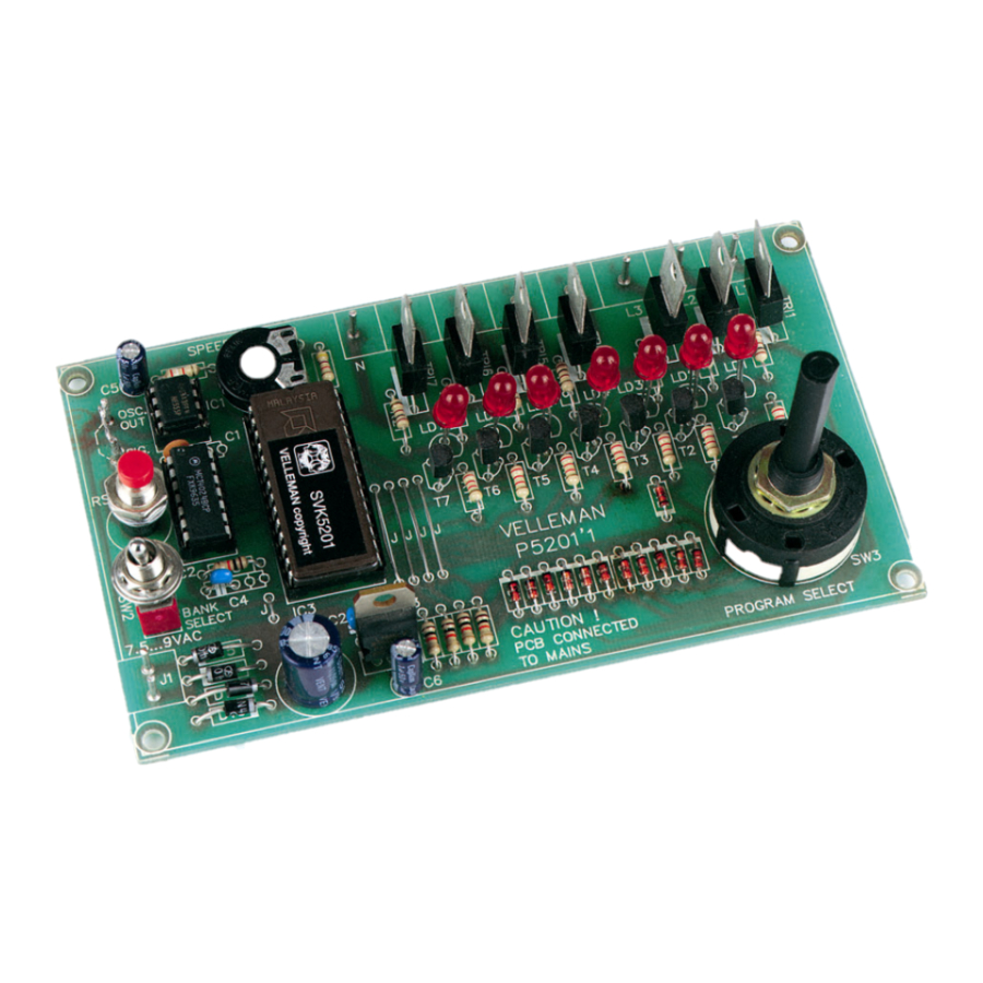
- Page 1 Total solder points: 240 Difficulty level: beginner 1 advanced LIGHT COMPUTER K5201 ILLUSTRATED ASSEMBLY MANUAL H5201IP-1...
-
Page 2: Specifications
Features & Specifications Features: Sixteen different patterns and 7 outputs provide a unique light show Easy pattern selection with rotary switch Adjustable effect speed External oscillator input Daisy-chain units to create even bigger light shows Special setting for two linked units to create 14 channel operation 7 LED pattern indication Specifications: Power supply : 7.5-9VAC or 12VDC / 250mA... -
Page 3: Assembly Hints
Assembly hints 1. Assembly (Skipping this can lead to troubles ! ) Ok, so we have your attention. These hints will help you to make this project successful. Read them carefully. 1.1 Make sure you have the right tools: • A good quality soldering iron (25-40W) with a small tip. - Page 4 Assembly hints 1.3 Soldering Hints : 1- Mount the component against the PCB surface and carefully solder the leads 2- Make sure the solder joints are cone-shaped and shiny 3- Trim excess leads as close as possible to the solder joint REMOVE THEM FROM THE TAPE ONE AT A TIME ! AXIAL COMPONENTS ARE TAPED IN THE CORRECT MOUNTING SEQUENCE !
- Page 5 Construction Resistors 1. Jumpers 4. IC socket. Watch the 1/4W position of the notch! J : 5x R... R1 : 4K7 (4 - 7 - 2 - B) 2. Diodes. Watch the polarity ! R2 : 39K (3 - 9 - 3 - B) IC1 : 8p R3 : 10K (1 - 0 - 3 - B)
-
Page 6: Electrolytic Capacitors
Construction 6. Trimmer 12. LEDs. Watch the polarity! 9. Electrolytic Capacitors Watch the polarity ! RV1 : 1M C5 : 1µF C6 : 1µF C... C7 : 1000µF 7. PCB tabs. 23mm 23m m LD... 0.9" CATHODE 10. Voltage regulator. VR1 : UA7805 SIG IN. -
Page 7: Rotary Switch
Construction 14. Switch 16. Rotary switch. SW2 : 1p SW... Internal Tooth Lock Washer 15. ICs. Watch the position Stop washer SW... of the notch! SW... IC1 : NE555 The 12-position rotary switch SW3 must be configured for 8 positions. IC2 : CD4024 IC3 : VK5201 (programmed Eeprom 2764C25) - Page 8 Assembly, Hook-up & Use 17. ASSEMBLY, HOOK-UP AND USE Attention : There is no transformer isolating this circuit from the mains. Therefore, all parts of the PCB carry a potentially lethal voltage. The circuit must be mounted in an adapted enclosure according to the applicable norms, so that no live parts can be touched or present any other danger.
- Page 9 SLOW 0.5mm 1.5mm 7.5...9VAC 0.25A L7 L6 L5 OSC. OUT SIG. IN K5201 RESET 0.5mm FIG. 1.0 BANK SELECT PROGRAM SELECT 7.5...9V To use the internal speed adjustment, connect ‘OSC OUT’ with ‘SIG IN’ by means of a wire jumper. A external...
- Page 10 50mA SLOW 2.5mm 2.5mm 7.5...9VAC 7.5...9VAC 0.25A 0.25A OSC. OUT OSC. OUT 0.5mm SIG. IN SLAVE MASTER SIG. IN K5201 K5201 RESET RESET 0.5mm 0.5mm BANK BANK SELECT SELECT PROGRAM SELECT PROGRAM SELECT 7.5...9V 7.5...9V FIG. 2.0 The ‘RESET’ button of the slave unit can be omitted. It is very important that each unit gets its own power...
- Page 11 Assembly, Hook-up & Use Do not use a single transformer for both units. Make sure the ‘L’ (live) of both kits is connected to the same phase of the mains. Not doing so will result in damage beyond repair of both kits, and the risk of fire. Use 4mm²...
- Page 12 Finishing 18. FINISHING When mounting the kit in an enclosure you should make sure the enclosure is sufficiently insulated according to local norms. The complete PCB is best fixed to the front panel of the casing, so that all controls are accessible and the LED's are visible.
- Page 13 Finishing FIG. 3.0...
- Page 14 Schematic diagram 19. Schematic diagram.
- Page 15 20. PCB...
- Page 16 VELLEMAN Components NV Legen Heirweg 33 9890 Gavere Belgium Europe www.velleman.be www.velleman-kit.com Modifications and typographical errors reserved © Velleman Components nv. H5201IP - 2004 - ED1 5 4 1 0 3 2 9 2 8 9 3 4 8...
Need help?
Do you have a question about the K5201 and is the answer not in the manual?
Questions and answers