
Related Manuals for Velleman-Kit K8000


Summary of Contents for Velleman-Kit K8000
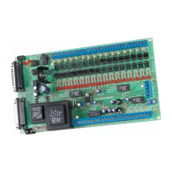
- Page 1 Computer interface board Total solder points: 839 5 ⌧ advanced Difficulty level: beginner 1 K8000 K8000 ILLUSTRATED ASSEMBLY MANUAL H8000IP-2...
- Page 2 Features & specifications Features : Optically isolated from computer. 16 optically isolated digital connections. 9 analogue outputs, of which one is high precision and 4 analogue inputs. A simple way of controlling using Turbo Pascal, Turbo C, Qbasic, Visual Basic. Printer bypass connector on board.
- Page 3 Assembly hints 1. Assembly (Skipping this can lead to troubles ! ) Ok, so we have your attention. These hints will help you to make this project successful. Read them carefully. 1.1 Make sure you have the right tools: • A good quality soldering iron (25-40W) with a small tip.
- Page 4 Assembly hints ⇒ Use the check-boxes to mark your progress. ⇒ Please read the included information on safety and customer service * Typographical inaccuracies excluded. Always look for possible last minute manual updates, indicated as ‘NOTE’ on a separate leaflet. 1.3 Soldering Hints : 1- Mount the component against the PCB sur- face and carefully solder the leads...
- Page 5 Construction Mount the components in the order indicated in the separate part list. The parts marked with (!) require special attention in the assembly instructions. IMPORTANT : Read the disk file READ.ME before commencing assembly. This file will report any updated changes. ATTENTION :If the card is to built as an expansion card (Slave) to one already connected tot the computer (Master), the components marked with S should not be mounted.
- Page 6 Construction Resistors. R7 : 100 (1-0-1-B) 1/2W R8 : 100 (1-0-1-B) R9 : 100 (1-0-1-B) R10 : 100 (1-0-1-B) R... R11 : 100 (1-0-1-B) R12 : 100 (1-0-1-B) R13 : 100 (1-0-1-B) R14 : 100 (1-0-1-B) R15 : 100 (1-0-1-B) R49 : 10 (1-0-0-B-9) (S) R16 : 100 (1-0-1-B) R17 : 100 (1-0-1-B) (S)
- Page 7 Construction 8. Dip Switch 11. PCB tab I/O1 … 16; GND; +5V SW1 : 2P DIP 12. Terminal blocks 9. Resistor Trimmer R... J1 : 2P J17 : 2P RV1, RV2 : 10K J2 : 2P J18 : 2P Rv1 = Vmax. J3 : 2P J19 : 2P Max DAC output voltage : 0 ...10V...
- Page 8 Construction 14. Relay 17. Electrolytic capacitors. Check the polarity ! C10 : 100µF C11 : 100µF C12 : 100µF C13 : 100µF C... RY1 : OUC-5 (S) C14 : 100µF C15 : 100µF 15. 25P sub D connectors C16 : 100µF C17 : 100µF C18 : 100µF C19 : 100µF...
- Page 9 Construction 19. Transformers 220V TRANSFORMER TRANSFO 1 : 1 X 15V (2X7,5V) TRANSFO 2 : 1 X 6V (S) 20. IC’s. check the position ! IC1 : 4N33 ! IC9 : 4N33 ! IC2 : 4N33 ! IC10 : 4N33 ! IC3 : 4N33 ! IC11 : 4N33 ! IC4 : 4N33 !
- Page 10 Information 21. Information If desired, a voltage divider or filter can be fitted on each analogue input. The voltage divider can be useful if a higher input voltage than normal is to be monitored. Normally only a maximum of 5V can be accepted by the input. The filter can be useful for eliminat- ing (mains) hum from the signal for example.
- Page 11 Connection numbering Conversion of current to voltage. In order to avoid interruptions, it is possible for a variable current to be measured as the reference input value which is used for current to voltage conversion. Here a variable current from 4 to 20 mA is converted to a voltage of 0.8 to 4V.
- Page 12 Test & connection 23. Test and Connection TEST Prior to testing the card by computer a number of "passive" tests can be done. Connect the connectors, MAINS N and L to the supply voltage. Normally no LEDs should light up. Measure the voltage on testpin +5V to see if the 5V supply voltage is present.
- Page 13 24. PCB...
- Page 14 Schematic diagram 25. Digital selection...
- Page 15 Opto coupler selection 26. Opto Coupler selection...
- Page 16 VELLEMAN KIT NV Legen Heirweg 33 9890 Gavere Belgium Europe Info ?: http://www.velleman.be Modifications and typographical errors reserved © Velleman Kit nv H8000IP - 2004 - ED2 5 4 1 0 3 2 9 2 9 1 1 7 4...
Need help?
Do you have a question about the K8000 and is the answer not in the manual?
Questions and answers