
Related Manuals for Velleman-Kit K8090


Summary of Contents for Velleman-Kit K8090
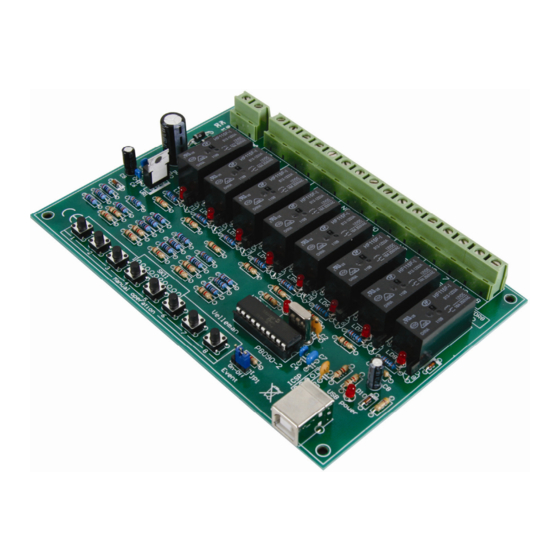
- Page 1 8 CHANNEL USB RELAY CARD Total solder points: 363 5 ⌧ advanced Difficulty level: beginner 1 K8090 K8090 ILLUSTRATED ASSEMBLY MANUAL H8090IP-1...
- Page 3 Features & specifications Eight relay channels controlled by your computer! Use your computer USB port to connect to the outside world. Connect up to 16A to each of the high power relays. Board space for extra VDR noise suppressors is provided and on board push buttons can be used to test/operate all the relays.
- Page 4 Assembly hints 1. Assembly (Skipping this can lead to troubles ! ) Ok, so we have your attention. These hints will help you to make this project successful. Read them carefully. 1.1 Make sure you have the right tools: • A good quality soldering iron (25-40W) with a small tip.
- Page 5 Assembly hints * Typographical inaccuracies excluded. Always look for possible last minute man- ual updates, indicated as ‘NOTE’ on a separate leaflet. 1.3 Soldering Hints : 1- Mount the component against the PCB surface and carefully solder the leads 2- Make sure the solder joints are cone-shaped and shiny 3- Trim excess leads as close as possible to the solder joint...
- Page 6 Construction 1. Diodes (check the polarity) 6. LEDs. Watch the polarity! D... CATHODE CATHODE D1 ... D10 : 1N4148 D11 ... D14 : 1N4007 LD1 ... LD11 : 3mm RED LD1 … LD8 : Output indication 2. Resistors. : USB DATA LD10 : USB power indication LD11...
- Page 7 Construction 10. Terminal blocks 15. Relays SK1 : 2p power supply SK2 ... SK9 : 2p (channels 1 ... 8) Important : Put an extra layer of solder on all pre-thinned PCB tracks, to improve their current handling capabilities. 11. Electrolytic capacitors. Watch the polarity ! 16.
- Page 8 Test & connection 19. Test and connection The card uses a separate supply for the relays and one for the board microcon- troller. Test 1: Connect a power supply of 9 to 10Vac or 12 to 14Vdc (minimum 500mA). • The power LED should turn on.
- Page 10 VDR1 VDR2 VDR3 VDR4 VDR5 VDR6 VDR7 VDR8 VDR300 VDR300 VDR300 VDR300 VDR300 VDR300 VDR300 VDR300 1N4007 1N4007 1N4007 1N4007 +12V +12V +12V +12V +12V +12V +12V +12V +12V 1N4148 1N4148 1N4148 1N4148 1N4148 1N4148 1N4148 1N4148 LD11 1000µ/25V LED3RL BC547 BC547 BC547...
- Page 12 VELLEMAN NV Legen Heirweg 33 9890 Gavere Belgium Europe Info ?: http://www.velleman.be Modifications and typographical errors reserved © Velleman nv H8090IP - 2010 5 4 1 0 3 2 9 4 1 2 0 5 0...
Need help?
Do you have a question about the K8090 and is the answer not in the manual?
Questions and answers