Table of Contents
Advertisement
Quick Links
Total solder points: 240
Skill level :
Beginner 1o 2o 3þ 4o 5o Advanced
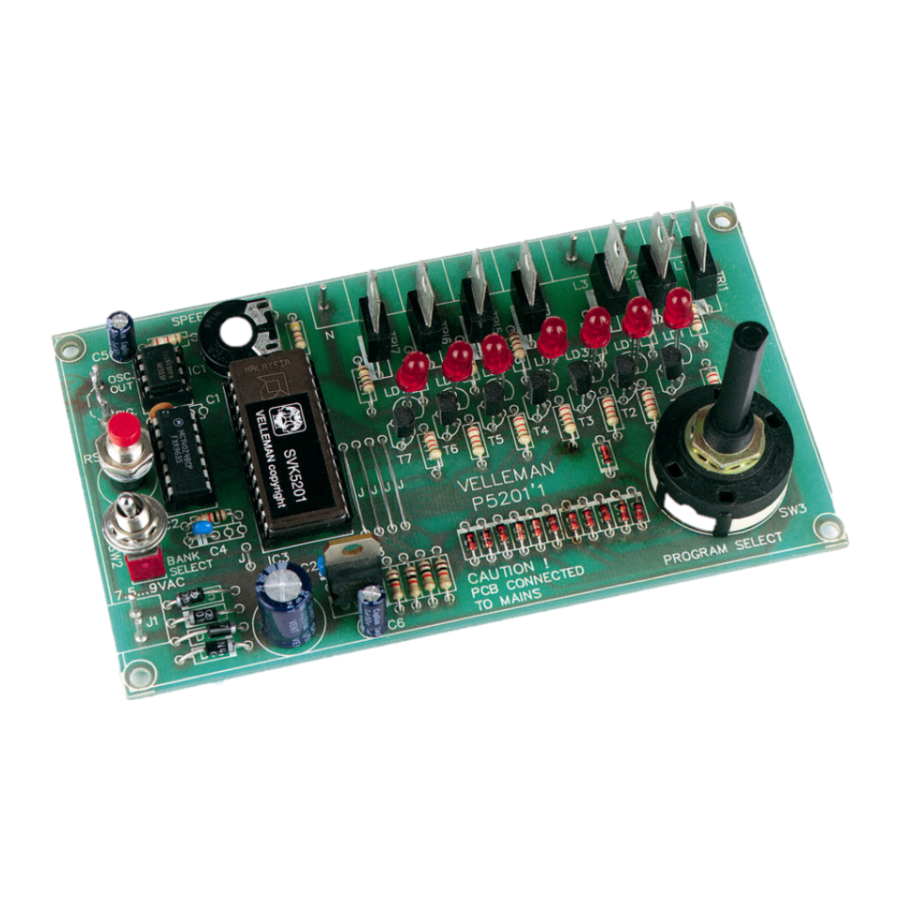
LIGHT COMPUTER
Features:
þ
Sixteen different patterns and 7 outputs provide a unique light show
þ
Easy pattern selection with rotary switch
þ
Adjustable effect speed
þ
External oscillator input
þ
Daisy-chain units to create even bigger light shows
þ
Special setting for two linked units to create 14 channel operation
þ
7 LED pattern indication
Specifications :
þ
Power supply : 7.5-9VAC or 12VDC / 250mA
þ
Load : 24-240VAC
þ
1.5A/channel max.
þ
Not suitable for inductive loads
þ Dimensions : 134x79mm (5.3"x3.1")
modifications reserved
ILLUSTRATED MANUAL
K5201
H5201P-ED1
Advertisement
Table of Contents

Related Manuals for Velleman-Kit K5201

Summary of Contents for Velleman-Kit K5201
- Page 1 Total solder points: 240 Skill level : Beginner 1o 2o 3þ 4o 5o Advanced LIGHT COMPUTER K5201 Features: þ Sixteen different patterns and 7 outputs provide a unique light show þ Easy pattern selection with rotary switch þ Adjustable effect speed þ...
- Page 2 COLOR= 2… 5 4K7= ( 4 - 7 - 2 - B ) 4K7= ( 4 - 7 - 0 - 1 - 1 ) COLOUR CODIFI- KLEUR CODICE CODIGO CODIGO VÄRI FÄRG FARVE FARGE FARB CODE CATION KODE SCHEMA DE COL- COLORE KOODI...
- Page 3 __________________________________________________________________________________________________________________________________________________________ 1. Assembly (Skipping this can lead to troubles ! ) Ok, so we have your attention. These hints will help you to make this project successful. Read them carefully. 1.1 Make sure you have the right tools: • A good quality soldering iron (25-40W) with a small tip.
-
Page 4: Wire Jumpers
_______________________________________________________________________________________________________________________________________________________ q R7 : 10K (1 - 0 - 3 - B) AXIAL COMPONENTS ARE q R8 : 2K2 (2 - 2 - 2 - B) TAPED IN THE CORRECT q R9 : 2K2 (2 - 2 - 2 - B) MOUNTING SEQUENCE ! q R10 : 2K2 (2 - 2 - 2 - B) START... -
Page 5: Electrolytic Capacitors
__________________________________________________________________________________________________________________________________________________________ 4. IC SOCKETS (Watch the posi- 7. ELECTROLYTIC CAPACITORS tion of the notch !) (Watch the polarity!) C... q C5 : 1µF q C6 : 1µF q IC1 : 8P q C7 : 1000µF q IC2 : 14P q IC3 : 28P 8. -
Page 6: Push Button
_______________________________________________________________________________________________________________________________________________________ 9. LEDs (Watch the polarity) 12. TRIACs 23mm LD... 0.9" CATHODE 19mm 0.7" q LD1 q LD2 q LD3 q TR1 : T410-600T; TIC216 or eq. q LD4 q TR2 : T410-600T; TIC216 or eq. q LD5 q TR3 : T410-600T; TIC216 or eq. q LD6 q TR4 : T410-600T;... -
Page 7: Rotary Switch
__________________________________________________________________________________________________________________________________________________________ 15. ROTARY SWITCH 16. ICs (Watch the position of the notch) q IC1 : 555 q IC2 : 4024 q SW3 q IC3 : VK5201... - Page 8 _______________________________________________________________________________________________________________________________________________________ 17. ASSEMBLY, HOOK-UP AND USE Assembly : The 12-position rotary switch SW3 must be configured for 8 positions. Turn the switch all the way counterclockwise. Remove the nut and the lockwasher Lift the stop washer and move it to position ‘8’ Put the lockwasher and nut back in place Take care when connecting and using this kit.
- Page 9 __________________________________________________________________________________________________________________________________________________________ 18. CONNECTION EXAMPLE FOR A SINGLE UNIT...
- Page 10 _______________________________________________________________________________________________________________________________________________________ 19. CASCADE OPERATION OF TWO UNITS...
- Page 11 __________________________________________________________________________________________________________________________________________________________ 20. DRILL PATTERN All values are in mm. (1mm = 0.04")
-
Page 12: Pcb Layout
_______________________________________________________________________________________________________________________________________________________ 21. PCB LAYOUT... - Page 13 __________________________________________________________________________________________________________________________________________________________ 22. DIAGRAM...
Need help?
Do you have a question about the K5201 and is the answer not in the manual?
Questions and answers