
Related Manuals for Wilo NL-HE Series


Summary of Contents for Wilo NL-HE Series
- Page 1 Pioneering for You Wilo NL-HE en Installation and operating instructions 3327453 • Ed.01/2021-01...
-
Page 3: Table Of Contents
6 Installation and electrical connection ............................ 16 Personnel qualifications...................................... 16 Operator responsibilities...................................... 16 Preparing the installation....................................... 16 Setting up the pump by itself (variant B, Wilo variant key) .......................... 17 Installing the pump unit on a base .................................. 17 Pipework........................................... 19 Aligning the unit........................................ 20 Electrical connection ...................................... - Page 4 11 Spare parts...................................... 39 11.1 Spare parts list ......................................... 40 12 Disposal...................................... 41 12.1 Oils and lubricants........................................ 41 12.2 Water-glycol mixture ...................................... 41 12.3 Protective clothing ......................................... 41 12.4 Information on the collection of used electrical and electronic products...................... 41 WILO USA 2021-01...
-
Page 5: General Information
Failure to observe the safety instructions will result in serious injuries or death! ƒ WARNING! Failure to follow the instructions can lead to (serious) injuries! ƒ CAUTION! Failure to follow the instructions can lead to property damage and a possible total loss. Installation and operating instructions Wilo NL-HE... - Page 6 Warning – suspended loads Personal protective equipment: wear a safety helmet Personal protective equipment: wear foot protection Personal protective equipment: wear hand protection Personal protective equipment: wear mouth protection Personal protective equipment: wear safety goggles Useful information WILO USA 2021-01...
-
Page 7: Personnel Qualifications
The procedure described in the installation and operating instructions for shutting down the product/unit must be strictly observed. ƒ Disconnect the device from the mains and secure it against being switched on again without authorization. Installation and operating instructions Wilo NL-HE... -
Page 8: During Operation
For a sound pressure level of 85 dB(A) and above, the operator must: ƒ Make it a mandatory requirement to wear hearing protection ƒ Demarcate the noisy areas. ƒ Take measures to reduce noise (e.g. insulation, noise barriers) WILO USA 2021-01... -
Page 9: Maintenance Tasks
Persons under the age of 18 must be supervised by a technician. Application/use Intended use The glanded pumps in the Wilo NL-HE series are intended for use as circulators in building services. The Wilo NL-HE pumps may only be used for: ƒ... -
Page 10: Improper Use
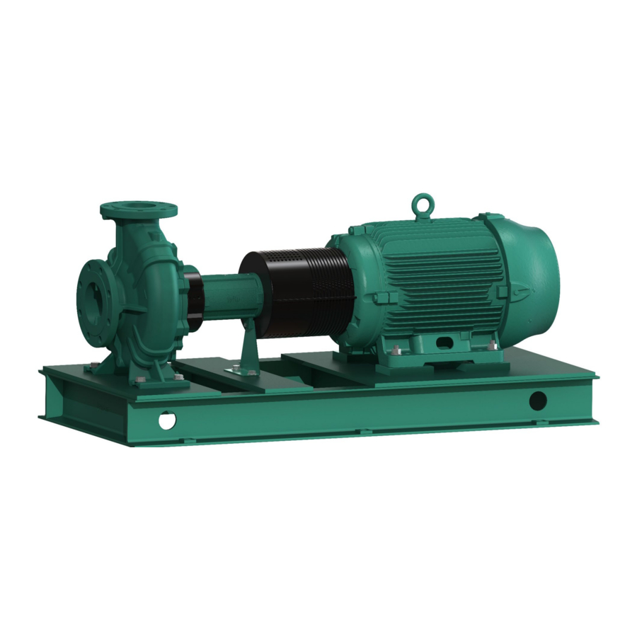
Product description Design The Wilo NL-HE pump is a single-stage back pull-out-centrifugal pump with spiral housing for horizontal installation. Motor dimensions in accordance with NEMA standards. Suitable Wilo control devices (e.g. Wilo-EFC Variable Frequency Drive) can control the power of the pumps continuously. -
Page 11: Type Key
ƒ Baseplate ƒ Coupling and coupling guard ƒ With or without electric motor ƒ Installation and operating instructions Pump by itself: ƒ NL-HE pump ƒ Bearing bracket without baseplate ƒ Installation and operating instructions Installation and operating instructions Wilo NL-HE... -
Page 12: Accessories
60 Hz without speed control 2-Pole (3550 rpm) 4-Pole (1750 rpm) – 0.75 Spatial mean value of sound-pressure levels within a cube-shaped measuring area at a distance of 1 m from the surface of the motor Table 1: Anticipated noise levels for standard pump (60 Hz) WILO USA 2021-01... -
Page 13: Permissible Forces And Torques On The Pump Flanges
Any defects must be notified to the transport company or the manufacturer immediately on the day of receipt of shipment. Subsequently notified defects can no longer be asserted. Installation and operating instructions Wilo NL-HE... -
Page 14: Transport
• Do not use the transport lugs on the pump or motor to lift the entire unit. They are only meant for transporting the individual components during installation or dismantling. Only remove the outer packaging at the place of utilization to ensure that the pump is not damaged during transport. WILO USA 2021-01... -
Page 15: Storage
Improper storage can lead to damage to the equipment. Damage caused by improper storage is not covered by the guarantee or warranty. ƒ Requirements at the storage location: – – clean – well-ventilated – free from vibrations – free from humidity Installation and operating instructions Wilo NL-HE... -
Page 16: Installation And Electrical Connection
Mount the pump in a readily accessible place. This makes it easier to complete inspec- tions, maintenance (e.g. mechanical seal change) or replacement in the future. ƒ A travelling crane or a device for attaching hoisting gear should be installed above the set-up site of large pumps. WILO USA 2021-01... -
Page 17: Setting Up The Pump By Itself (Variant B, Wilo Variant Key)
The base must be able to support the unit installed on the baseplate indefinitely. The base must be level to ensure there is no tension on the baseplate or unit. Wilo recommends using premium, non-shrink concrete of an adequate thickness for manufacturing. This would pre- vent vibrations from being transmitted. - Page 18 Installation and electrical connection Wilo recommends initially pouring the concrete base up to about 1 inch below the planned height. The surface of the concrete base must be well contoured before curing. Remove the pipe sleeves after the concrete cures. When the concrete base is poured out, insert steel rods vertically into the base at regular in- tervals.
-
Page 19: Pipework
ƒ The pipes must be fixed in such a way that the pump does not have to support the weight of the pipes. ƒ Clean, flush and purge the unit before connecting the pipes. Installation and operating instructions Wilo NL-HE... -
Page 20: Aligning The Unit
Sleeve size Max. (ref) EPDM Allowable Misalignment Parallel Angular 7600 0.01 0.25 0.043 1.09 7600 0.015 0.38 0.056 1.42 6000 0.015 0.38 0.07 1.78 5250 0.02 0.51 0.081 2.06 4500 0.02 0.51 0.094 2.39 3750 0.025 0.64 0.109 WILO USA 2021-01... - Page 21 Max. angular misalignment with n = 1,800 rpm >K [in] 0.029 0.031 0.039 0.051 0.067 0.079 0.090 0.102 0.126 0.161 0.181 0.213 0.248 0.256 0.303 0.354 0.024 Table 5: Allowable Misalignment for flexible jaw couplings Installation and operating instructions Wilo NL-HE...
- Page 22 “Allowable Misalignment for flexible jaw couplings”. This requirement applies to every operating status - including operating temperature and inlet pressure. Using a calliper gauge, circumferentially check the distance between the two coupling halves. Fig. 16: Checking the axial alignment with a calliper gauge – circumferential check WILO USA 2021-01...
- Page 23 Additional shims are needed. ƒ Finally, check the functioning of the coupling and shaft. The coupling and shaft must be easy to turn by hand. ƒ After correct alignment, mount the coupling guard. Installation and operating instructions Wilo NL-HE...
-
Page 24: Electrical Connection
An inadequate mains design can lead to system failures and cable fires due to mains overload! If the wrong voltage is applied, the pump can be damaged! • Ensure that the current type and voltage of the mains connection correspond to the specifications on the motor rating plate. WILO USA 2021-01... - Page 25 • Allow the pump to cool down at ambient temperature after switching it off! • Observe local regulations. CAUTION Risk of property damage due to incorrect insulation! The discharge cover and the bearing bracket must not be insulated. Installation and operating instructions Wilo NL-HE...
-
Page 26: Commissioning
Risk of material damage due to the formation of condensate! When using the pump in air-conditioning or cooling applications, the formation of con- densate can cause pump corrosion. WILO USA leaves insulation of the pump to the dis- cretion of the installer. -
Page 27: Checking The Direction Of Rotation
• Only operate the pump within the permissible operating range. Once all preparatory work has been properly completed and all necessary precautionary measures have been taken, the pump is ready to start. Before starting up the pump, check whether: Installation and operating instructions Wilo NL-HE... -
Page 28: Switching Frequency
• Only switch on the pump again when the motor is at a complete standstill. A maximum of 6 connections per hour are permitted in accordance with IEC 60034-1. It is recommended that repeated activations occur at regular intervals. WILO USA 2021-01... -
Page 29: Shutdown
Maintenance/repair It is recommended to have the pump serviced and checked by the Wilo customer service. Maintenance and repair work require the pump be partially or completely dismantled. The pump housing can be installed in the piping. - Page 30 • Reinstall any uninstalled safety devices, such as terminal box covers, once the work is complete. WARNING Sharp edges on the impeller! Sharp edges can form on the impeller. There is danger of limbs being severed! Protective gloves must be worn to protect against cuts. WILO USA 2021-01...
-
Page 31: Personnel Qualifications
Wilo recommends checking the flexible coupling elements regularly and replacing them at the first sign of wear. ƒ Wilo recommends briefly putting the standby pumps into operation at least once a week to ensure they are always ready for operation. Maintenance tasks The bearing bracket of the pump is equipped with rolling bearings that have lifetime lubric- ation. -
Page 32: Dismantling
If present: Remove the intermediate sleeve of the coupling. ƒ Remove the fastening screws of the motor from the baseplate. NOTICE Observe the section drawing in the chapter “Spare parts”. 9.5.1 Dismantling the slide-in unit Fig. 18: Removing the slide-in unit WILO USA 2021-01... - Page 33 2. Remove the rotating part of the mechanical seal (9.1). 3. Loosen the interior hexagonal head screws (15) and remove the housing cover (10). 4. Remove the stationary part of the mechanical seal (9.1). Installation and operating instructions Wilo NL-HE...
-
Page 34: Installation
• Any damage to the pump connection cable should only ever be repaired by a quali- fied electrician. • Observe the installation and operating instructions for the pump, motor and other accessories! • Reinstall any uninstalled safety devices, such as terminal box covers, once the work is complete! WILO USA 2021-01... - Page 35 6. Fasten the pump support foot (8.1) with the hexagon head screw (8.2) and lock washer (8.3). 9.6.2 Assembling the slide-in unit Version with mechanical seal (optional: mechanical seal on the sleeve) Fig. 26: Housing cover, mechanical seal Installation and operating instructions Wilo NL-HE...
- Page 36 4. Put the slide-in unit down at a safe workplace. To continue dismantling the slide-in unit, fix it vertically in position with the drive shaft facing downward. The kit must be removed vertically to avoid damage to the impellers and other parts. 5. Insert a new housing seal (1.2). WILO USA 2021-01...
-
Page 37: Troubleshooting Possible Causes And Remedies
ƒ Telephone or written support. ƒ On-site support. ƒ Inspection and repair at the factory. Costs may be incurred if you request customer services! Please contact customer services for more information. Installation and operating instructions Wilo NL-HE... -
Page 38: Troubleshooting
The viscosity or density – Check the pump di- of the fluid is higher than mensioning (consult with the design value the manufacturer) The pump is strained Correct the pump install- ation WILO USA 2021-01... -
Page 39: Spare Parts
Table 12: Causes of error and remedies Spare parts Spare parts may be ordered via a local installer and/or Wilo customer service. List of original spare parts: Refer to the Wilo spare parts documentation and the following information in these installation and operating instructions. -
Page 40: Spare Parts List
2.3 2.4 2.3 2.4 4.2 4.3 4.1B 4.1A 8.1 8.3 Fig. 31: Pump with mechanical seal Item no. Description Number Safety-relevant Pump housing Flat gasket Impeller Disc Disc Shaft Ball bearing 4.1A Ball bearing 4.1B Cover V-gasket Retaining ring WILO USA 2021-01... -
Page 41: Disposal
Observe the locally applicable regulations! Please consult your local municipality, the nearest waste disposal site, or the dealer who sold the product to you for information on proper disposal. See www.wilo‑recycling.com for more information about recycling. Subject to change without prior notice! - Page 44 Local contact at www.wilo.com/contact WILO USA LLC. 9550 W. Higgins Rd. #300 Rosemont, IL 60018 Tel. +1 (262) 204-6600 Fax +1 (229) 584-0234 info.us@wilo.com www.wilo.com/us/en_us/ WILO Canada Inc. Bay 8, 925 - 30th Street NE. Calgary, Alberta, T2A 5L7 Canada Tel.
Need help?
Do you have a question about the NL-HE Series and is the answer not in the manual?
Questions and answers
WHAT BEARINGS DOES A WILO NL 65/315-44 TAKE