Table of Contents
Advertisement
Quick Links
Manual, Compact Outdoor SSPAs (208495)
➤ General Information (216595-1)
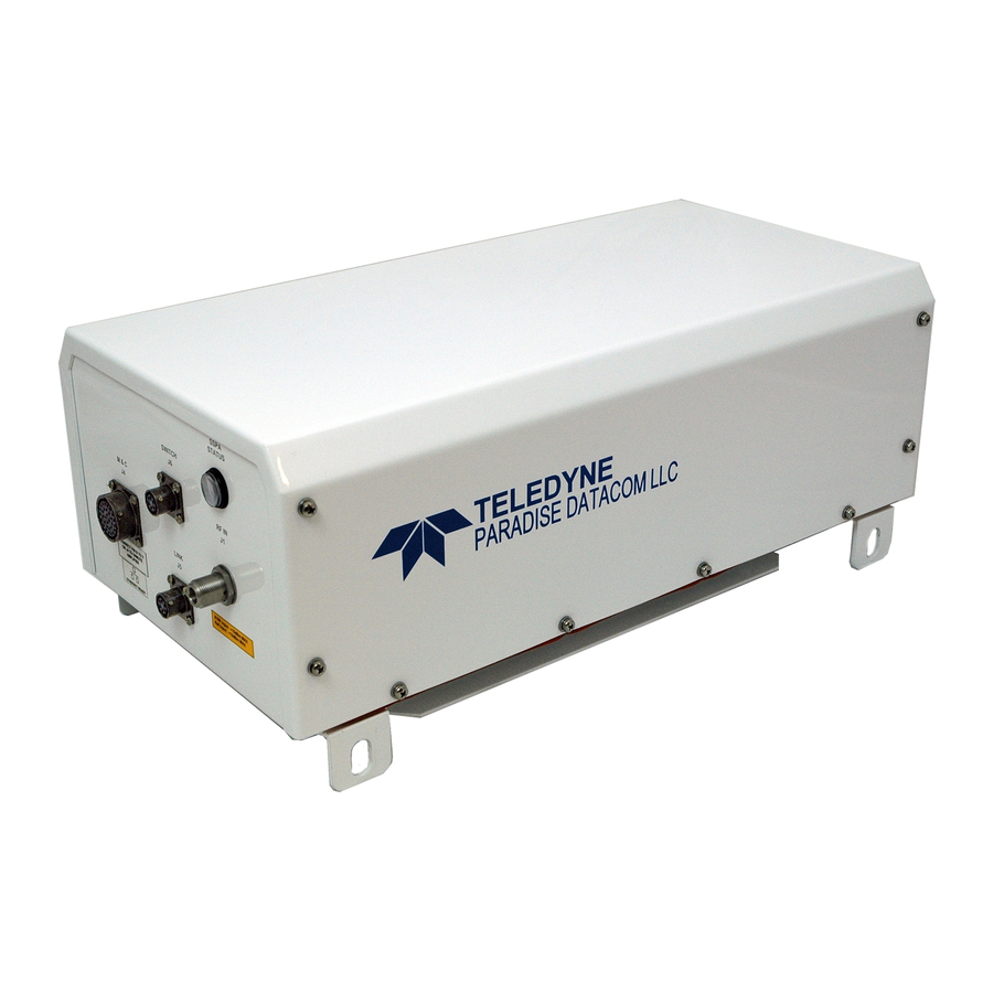
➤ Unit Description (208495-1)
➤ Quick-Start (216595-2)
➤ SSPA Operational Basics (216595-3)
➤ L-Band Operation (216594-3)
➤ Maintenance and Troubleshooting (208495-2)
➤ Maintenance Switch Mode (216595-4)
➤ Redundant System Operation (216595-5)
➤ Phase Combined System Operation (216595-6)
➤ Remote Control Protocol (216595-7)
➤ Performance Tests (216595-8)
➤ SSPA Control with Universal M&C Software (216594-2)
➤ Use and Disclosure of Data (216594-1)
Drawing Number: 208495
UNCONTROLLED WHEN PRINTED!
You can view the latest revision of this manual on the Teledyne Paradise Datacom web site:
http://www.paradisedatacom.com/xml/208495/208495.xml
USE AND DISCLOSURE OF DATA
EAR99 Technology Subject to Restrictions Contained in http://www.paradisedatacom.com/xml/216594/216594-1.xml
Last Modified: 28 January 2020
Revision Y
ECO 18899
1 of 1
Advertisement
Table of Contents

Related Manuals for Teledyne SSPA


Summary of Contents for Teledyne SSPA
- Page 1 ➤ SSPA Control with Universal M&C Software (216594-2) ➤ Use and Disclosure of Data (216594-1) UNCONTROLLED WHEN PRINTED! You can view the latest revision of this manual on the Teledyne Paradise Datacom web site: http://www.paradisedatacom.com/xml/208495/208495.xml USE AND DISCLOSURE OF DATA EAR99 Technology Subject to Restrictions Contained in http://www.paradisedatacom.com/xml/216594/216594-1.xml...
- Page 2 THIS PAGE LEFT INTENTIONALLY BLANK...
- Page 3 Drawing Number: 216595-1 Revision - RA 7714 06 November 2019 UNCONTROLLED WHEN PRINTED! You can view the latest revision of this manual section on the Teledyne Paradise Datacom web site: http://www.paradisedatacom.com/xml/216595/216595-1.xml USE AND DISCLOSURE OF DATA EAR99 Technology Subject to Restrictions Contained in http://www.paradisedatacom.com/xml/216594/216594-1.xml.
- Page 4 Outdoor SSPAs, General Information (216595-1) This section provides the general information for the Teledyne Paradise Datacom Outdoor Solid State Power Amplifier (SSPA) family of products, including the Compact Outdoor SSPA and High Power Outdoor SSPA. 2 of 10...
- Page 5 Outdoor SSPAs, General Information (216595-1) Refer to the SSPA's specification sheet for complete specifications. The latest revision of the specification sheets for the Compact Outdoor SSPA and High Power Outdoor SSPA are available on the Teledyne Paradise Datacom web site: www.paradisedata.com.
- Page 6 If it is, have a representative from the shipping company present when the container is opened. Perform a visual inspection of the equipment to make sure that all items on the packing list are enclosed. If any damage has occurred or if items are missing, contact: Teledyne Paradise Datacom 328 Innovation Blvd., Suite 100 State College, PA 16803 USA...
- Page 7 Outdoor SSPAs, General Information (216595-1) To protect the SSPA Chassis during shipment, use high quality commercial packing methods. When possible, use the original shipping container and its materials. Reliable commercial packing and shipping companies have facilities and materials to adequately repack the instrument.
-
Page 8: High Voltage Hazards
Outdoor SSPAs, General Information (216595-1) Potential safety hazards exist unless proper precautions are observed when working with this unit. To ensure safe operation, the user must follow the information, cautions and warnings provided in this manual as well as the warning labels placed on the unit itself. -
Page 9: Rf Transmission Hazards
Outdoor SSPAs, General Information (216595-1) Operators should be familiar with procedures to employ in the event of an emergency, i.e., remove all power, CPR, etc. Large DC currents are generated to operate the RF Module inside of the enclosure. Extreme caution is required when the enclosure is open and the amplifier is operating. -
Page 10: High Leakage Current
High Potential for Waveguide Arcing As with all systems which utilize high power signals within waveguide, the potential exists for an electric arc to form. To minimize this risk, Teledyne Paradise Datacom requires all waveguide be pressurized and dehydrated. 8 of 10... - Page 11 Outdoor SSPAs, General Information (216595-1) When working with high power amplifier systems that operate into waveguide, the inadvertent creation of arcs is always a concern. An arc in waveguide is the air discharge breakdown due to the ionization of the air molecules by electrons. This breakdown in waveguide occurs when the rate of electron production becomes greater than the loss of electrons to diffusion to the surrounding walls.
- Page 12 RA 7714 Last Modified: 06 November 2019 UNCONTROLLED WHEN PRINTED! You can view the latest revision of this manual section on the Teledyne Paradise Datacom web site: http://www.paradisedatacom.com/xml/216595/216595-1.xml USE AND DISCLOSURE OF DATA EAR99 Technology Subject to Restrictions Contained in http://www.paradisedatacom.com/xml/216594/216594-1.xml.
- Page 13 Drawing Number: 208495-1 Revision Y ECO 18899 28 January 2020 UNCONTROLLED WHEN PRINTED! You can view the latest revision of this manual section on the Teledyne Paradise Datacom web site: http://www.paradisedatacom.com/xml/208495/208495-1.xml USE AND DISCLOSURE OF DATA EAR99 Technology Subject to Restrictions Contained in http://www.paradisedatacom.com/xml/216594/216594-1.xml.
- Page 14 Unit Description, Compact Outdoor SSPA (208495-1) This section provides information for the initial inspection, installation, external connections, and shipment of the Compact Outdoor SSPA unit. 2 of 13...
- Page 15 Unit Description, Compact Outdoor SSPA (208495-1) When the unit is received, an initial inspection should be completed. Ensure that the shipping container is not damaged. If it is, have a representative from the shipping company present when the container is opened. Perform a visual inspection of the Compact Outdoor Amplifier to make sure that all items on the packing list are enclosed.
-
Page 16: Rf Input (J1) [N-Type (F)]
RF Input (J1) [N-type (F)] The RF Input connector is a type N female connector. The Compact Outdoor SSPA has a default maximum nominal gain of 75 dB minimum. Therefore the maximum input signal required to saturate the amplifier can be calculated as: Input Power = Psat - 75 dB For example, if a 50 W Ku-Band Compact Outdoor amplifier is used in a system it has a Psat = 47.0 dBm. -
Page 17: Rf Output Sample Port (J3) [N-Type (F)]
Note: Different manufacturers of the MS3116F18-32P circular connector use different labeling conventions, and pin "j" may appear to be pin "I". This manual uses the convention of pin "j". See the SSPA Operational Basics section for details on special functions available on Port J4. Table 1: M&C Port (J4) Pin-Outs... - Page 18 Unit Description, Compact Outdoor SSPA (208495-1) Signal Type Function Notes Closure to Unit powers up muted; This line must be pulled Mute Input Disables DC Power to HPA Ground to ground (V) to enable amplifier Closure to Auxiliary Input Auxiliary Input...
-
Page 19: Link Port (J5) [Ms3112E10-6S]
Unit Description, Compact Outdoor SSPA (208495-1) PGM Enable Flash Firmware Port Reserved for Programming Note: See previous revisions of this manual for units with serial numbers less than 300000. Link Port (J5) [MS3112E10-6S] The interface connector is used to connect between two Compact Outdoor Amplifiers when used in a 1:1 redundant system. -
Page 20: Dc Input Option [Ms3102E-20-29P]
DC Input Option, 300W C-Band Unit The 300W C-Band Compact Outdoor SSPA can be configured with a DC Input Voltage power supply. The DC Input Voltage can range from 42-60 VDC. When using a DC input voltage, the circular MIL connector (MS3102E-20-15P), J7, is configured per Table 6. -
Page 21: Vdc Output Port (J8) [Ms3112E10-6S]
Unit Description, Compact Outdoor SSPA (208495-1) No Connection +15 VDC Output Port (J8) [MS3112E10-6S] The +15 VDC Output, J8, is located on the bottom side of the amplifier as shown in Figure 4. This provides +15 VDC and up to 1 Amp current to any external equipment. It is a 6-pin MS-type connector (see Table 7 for pin-outs) and mates with MS3116F10-6P. -
Page 22: Summary Alarm Indicator
In system configurations, ensure that each unit in the system has sufficient ambient airflow, and adequate space to maintain the fans for each unit. Figure 5 shows an improper method for mounting a Compact Outdoor SSPA system. Not only do the fans oppose each other, thereby potentially causing thermal issues, but the configuration leaves insufficient space to remove the fans to periodically clean the heatsink. -
Page 23: Unit Weights
Remove the cover before attempting to connect a cable to the connector. Unit Weights The Compact Outdoor SSPA is available in a variety of frequency bands and power levels, and have a multitude of options which makes each unit weigh slightly different from another. -
Page 24: Installation
Installation Locate the mounting studs on the bottom of the Compact Outdoor SSPA unit. Using a 1/2" bolt, two flat washers, and a 1/2" nut, firmly bolt one mounting bracket to each mounting stud, as shown in Figure 6. Be sure each bracket is vertical, and the top flange of the mounting bracket points away from the unit. - Page 25 ECO 18899 Last Modified: 28 January 2020 UNCONTROLLED WHEN PRINTED! You can view the latest revision of this manual section on the Teledyne Paradise Datacom web site: http://www.paradisedatacom.com/xml/208495/208495-1.xml USE AND DISCLOSURE OF DATA EAR99 Technology Subject to Restrictions Contained in http://www.paradisedatacom.com/xml/216594/216594-1.xml.
- Page 26 THIS PAGE LEFT INTENTIONALLY BLANK...
- Page 27 Drawing Number: 216595-2 Revision - RA 7714 06 November 2019 UNCONTROLLED WHEN PRINTED! You can view the latest revision of this manual section on the Teledyne Paradise Datacom web site: http://www.paradisedatacom.com/xml/216595/216595-2.xml USE AND DISCLOSURE OF DATA EAR99 Technology Subject to Restrictions Contained in http://www.paradisedatacom.com/xml/216594/216594-1.xml.
- Page 28 Outdoor SSPAs, Quick-Start (216595-2) Teledyne Paradise Datacom Outdoor SSPAs are available with a standard Ethernet & RS-232/RS-485 interface. This section summarizes the connections to a remote computer for various remote communications. See the appropriate description of the Compact Outdoor or High Power Outdoor connections to Port J4.
- Page 29 Outdoor SSPAs, Quick-Start (216595-2) For convenience all amplifiers ship with a 'Quick-Start' communications cable. This allows the user to immediately connect the amplifier to a PC and begin operation. Ethernet ready units ship with a Quick-Start cable fitted with a 10-base T connector as shown in Figure 1.
-
Page 30: Set Pc Configuration
This section describes the necessary steps to communicate with an amplifier using either the Ethernet or RS-232 Quick-Start cables and the Teledyne Paradise Datacom Universal M&C Software. The Universal M&C Software is a free Windows-based application that can be downloaded from the company web site, www.paradisedata.com. -
Page 31: Quick-Start Rs-232 Connection
4. When shipped from the factory, the amplifier is set to start up muted. 5. Connect the supplied Quick-Start Control Cable from Port J4 of the SSPA to one of the COM ports on your computer. This connection will unmute the amplifier. Review the cable schematic in Figure 2. - Page 32 IMPORTANT! If the Quick Start cable is attached to Port J4 of the unit before power is applied, the unit will always start up with the default IP settings. Teledyne Paradise Datacom recommends that the operator build a custom cable that leaves Port J4 pins "j" and "e" unpopulated. This custom cable will prevent the default settings from being used if the unit experiences an unexpected power cycle.
- Page 33 Outdoor SSPAs, Quick-Start (216595-2) Teledyne Paradise Datacom provides a free version of its Universal Monitor and Control (M&C) Software available for download from its web site. Install the software on a PC running Windows 7 or later. Navigate to the Support > Downloads page and click on the latest version of the sofware to download the zip file.
-
Page 34: Navigating The Web M&C
15 alpha-numeric characters. If you forget the web password you will need to connect to SSPA via Universal M&C to verify it. Click on the [Log In] button to open the M&C control in the web browser. -
Page 35: Communications Settings Tab
Fault indicators are either colored green when no fault condition exists, or red when a fault condition exists. The top bar of SSPA Monitor and Control application shows whether the connected unit is exhibiting a summary fault, and also displays the device's online status, transmit status, Forward and Reflected RF power (if available) and RF module core temperature. -
Page 36: General Settings Tab
Gain Control; Attenuation Level adjustment (in dB); Automatic Level Control (ALC) RF Level (in dBm); Mute Setting (Mute clear or Mute set); and Fan Speed selection (High, Low or Auto). Note: The High Power Outdoor SSPA initially starts up in the Muted state; Change the Mute Setting in the General Settings tab to enable Transmit RF. - Page 37 RA 7714 Last Modified: 06 November 2019 UNCONTROLLED WHEN PRINTED! You can view the latest revision of this manual section on the Teledyne Paradise Datacom web site: http://www.paradisedatacom.com/xml/216595/216595-2.xml USE AND DISCLOSURE OF DATA EAR99 Technology Subject to Restrictions Contained in http://www.paradisedatacom.com/xml/216594/216594-1.xml.
- Page 38 THIS PAGE LEFT INTENTIONALLY BLANK...
- Page 39 Drawing Number: 216595-3 Revision - RA 7714 06 November 2019 UNCONTROLLED WHEN PRINTED! You can view the latest revision of this manual section on the Teledyne Paradise Datacom web site: http://www.paradisedatacom.com/xml/216595/216595-3.xml USE AND DISCLOSURE OF DATA EAR99 Technology Subject to Restrictions Contained in http://www.paradisedatacom.com/xml/216594/216594-1.xml.
-
Page 40: Remote Communication Connections
Outdoor SSPAs, Operational Basics (216595-3) The Teledyne Paradise Datacom outdoor amplifier is available with a standard RS-232/RS-485 serial communications interface or an optional Ethernet & RS-232/RS-485 interface. This section summarizes the connections to a remote computer for various remote communications. -
Page 41: Compact Outdoor Sspas In Legacy Systems
Outdoor SSPAs, Operational Basics (216595-3) Figure 4: J4 Connections for RS-232 Communication Legacy Compact Outdoor SSPAs Compact Outdoor SSPAs with serial numbers of less than 300,000 did not include isolated grounds for RS-232/RS-485 serial communications. The remote communication connections are slightly different and outlined in Figures 5 and 6. Figure 5 shows the proper configuration of J4 for communication over RS-485 for legacy units. - Page 42 Outdoor SSPAs, Operational Basics (216595-3) Figure 7: J4 Connections for RS-485 Communications for Compact Outdoor SSPAs of Serial Numbers > 300,000 in systems with M&C cables designed for Compact Outdoor SSPAs of Serial Numbers < 300,000 If it is not possible to modify the existing cable harness or otherwise externally connect the chassis ground Pin V to the isolated return at Pin d as shown in Figure 7, consult the factory for other options.
-
Page 43: Automatic Addressing
Pins j and e on the J4 M&C connector have internal pull-ups and if left disconnected will remain in logic high state. The reverting function of the SSPA is active only on initial power-up. Any alterations to the pins' state after start-up will allow the SSPA to use internal EEPROM settings to select the baud rate and protocol. -
Page 44: Amplifier Enable (Mute/Unmute) (J4)
3. Turn on the SSPA and remove the jumpers; 4. Connect to the SSPA over serial protocol and use the Universal M&C application to select the desired settings for protocol and baud rate. Settings will take effect on the next SSPA power-up. -
Page 45: Gain Adjust Input (J4)
The outdoor unit is equipped with an internal attenuator, allowing up to 20.0 dB of attenuation to be applied to the RF signal path, with 0.1 dB accuracy. Typically it will allow user to set SSPA linear gain from maximum 75 dB to minimum 55 dB (refer to the product spec sheet for details). - Page 46 Outdoor SSPAs, Operational Basics (216595-3) Figure 8: Set Gain Control to External or Serial Port and Attenuation to 10.0 dB Adjust the input signal to achieve the desired RF output and allow amplifier output to stabilize; Note: If the ALC level is set outside the amplifier's detectable forward RF range, the ALC Level will automatically reset to either the maximum or minimum value, depending on whether the setting was higher or lower than the detectable range.
-
Page 47: Rf Power Detector (J4, Pin R)
Outdoor SSPAs, Operational Basics (216595-3) Figure 10: Disable Forward RF Fault Status Alarms (J4) A variety of alarm signals are present at the M&C connector, J4. Both Form-C relays and open collector outputs are available. An amplifier summary alarm is available in both Form C relay and open collector output. Detailed internal faults are available in open collector form and include: voltage, current, and over-temperature. - Page 48 RA 7714 Last Modified: 06 November 2019 UNCONTROLLED WHEN PRINTED! You can view the latest revision of this manual section on the Teledyne Paradise Datacom web site: http://www.paradisedatacom.com/xml/216595/216595-3.xml USE AND DISCLOSURE OF DATA EAR99 Technology Subject to Restrictions Contained in http://www.paradisedatacom.com/xml/216594/216594-1.xml.
- Page 49 Drawing Number: 216594-3 Revision A ECO 18855 11 October 2019 UNCONTROLLED WHEN PRINTED! You can view the latest revision of this manual section on the Teledyne Paradise Datacom web site: http://www.paradisedatacom.com/xml/216594/216594-3.xml USE AND DISCLOSURE OF DATA EAR99 Technology Subject to Restrictions Contained in http://www.paradisedatacom.com/xml/216594/216594-1.xml.
- Page 50 It is important to remember the requirement of a 10 MHz reference oscillator when operating an SSPA with ZBUC converter (SSPB). If the 10 MHz reference is not present, the M&C will report a BUC alarm and the SSPA module will mute. This ensures that no spurious or 'off frequency' transmission could originate from the unit.
- Page 51 L-Band Operation (216594-3) This section describes the features available in the Teledyne Paradise Datacom ZBUC converter. The ZBUC converter is available as an option for the C-Band, X-Band and Ku-Band SSPA. Table 1 shows the specifications for the respective frequency plans.
-
Page 52: Smart Reference Technology
Smart Reference Technology Teledyne Paradise Datacom's ZBUC® block up converter comes standard with smart reference technology. Smart reference technology allows the system operator to change external system reference frequency without any system configuration required. The ZBUC converter will automatically sense and lock to a 10 MHz or 50 MHz system reference frequency. With the internal reference option installed, the ZBUC will operate with no external reference applied. - Page 53 L-Band Operation (216594-3) Internal Crystal Reference Specs The 10 MHz crystal reference used in the internal reference option of the zBUC converter has the following specifications: Frequency Stability: ≤ ± 3 · 10-8 over temperature range -20 to +85 °C ≤...
- Page 54 IFL. An embedded controller enables remote communication and fault detection via the IF input between the SSPA and a Teledyne Paradise Datacom Q-Series L-Band modem. This signal consists of a 650 KHz Frequency Shift Keyed carrier that is multiplexed onto the L-Band input IFL along with the 10 MHz reference signal.
- Page 55 L-Band Operation (216594-3) This section shows the Rack Mount SSPB in a common system application. Figure 3 shows the amplifier used with a Teledyne Paradise Datacom Q-Flex L-Band Modem. Figure 3: SSPB Chassis with Q-Flex Satellite Modem 7 of 12...
- Page 56 L-Band Operation (216594-3) Consideration should be given to using a high quality IFL between the indoor and outdoor equipment. The system designer must always consider the total cable loss for a given length and also the implications of the slope of attenuation across the 950 to 1450 MHz bandwidth.
-
Page 57: Option 1: Internal Reference
L-Band Operation (216594-3) When redundant systems are configured with Block Up Converters, the systems engineer must be know whether the BUCs have internal 10 MHz reference oscillators or if they are configured for external 10 MHz reference only. When the Block Up Converter loses its 10 MHz reference, the converter will trigger an alarm condition. - Page 58 L-Band Operation (216594-3) Figure 5: 1:1 Redundant System, Input Switching, Internal Reference BUCs Figure 6 shows the standard configuration for 1:1 systems with input splitting. The SSPBs will automatically detect and switch to an external reference applied at the IF input. Figure 6: 1:1 Redundant System, Input Splitter, Internal or External Reference BUCs Option 2: Separate External Reference Supplied to Standby Amplifier This configuration can be used when the L-Band IF signal and 10 MHz are on the same input and the Block Up Converters...
- Page 59 L-Band Operation (216594-3) Figure 8: 1:1 Redundant System, Reference Diplexed to Standby Amplifier Option 3: Single External Reference Diplexed to Each Amplifier This configuration can be used when the L-Band IF signal and 10 MHz are on separate coaxial inputs, and the BUCs are configured for external reference.
- Page 60 In this case, individual 10 MHz references are diplexed to the IF input of each amplifier as shown in Figure 11 and Figure 12. This gives the systems engineer the greatest flexibility and control over the 10 MHz reference input to each SSPA.
- Page 61 Drawing Number: 208495-2 Revision Y ECO 18899 28 January 2020 UNCONTROLLED WHEN PRINTED! You can view the latest revision of this manual section on the Teledyne Paradise Datacom web site: http://www.paradisedatacom.com/xml/208495/208495-2.xml USE AND DISCLOSURE OF DATA EAR99 Technology Subject to Restrictions Contained in http://www.paradisedatacom.com/xml/216594/216594-1.xml.
- Page 62 Maintenance and Troubleshooting, Compact Outdoor SSPA (208495-2) This section describes some of the standard maintenance practices that can be performed on the Compact Outdoor Amplifier and tips to troubleshoot common customer issues. 2 of 8...
- Page 63 Maintenance and Troubleshooting, Compact Outdoor SSPA (208495-2) It is recommended that the cooling system be checked at least once per month. This involves visually inspecting the fan intakes to make sure that there is no obstructions over the intake. The Windows-based M&C program can be used to check the amplifier base plate temperature.
-
Page 64: Fan Replacement
Note: Failure to use the proper fan tray will damage your amplifier! It is possible to modify an older Compact Outdoor SSPA to be fitted with a three fan cooling fan assembly in place of a two fan assembly. This should be done by a Teledyne Paradise Datacom technician, using the procedure outlined in drawing number 206573. -
Page 65: Web Upgrade Procedure
Teledyne Paradise Datacom digital engineers continually strive to improve the performance of CO SSPA software and firmware. As this occurs, software and firmware upgrades are made available. The web upgrade is performed over the SSPA IP port and does not require any special software. It can be performed through any suitable web browser. - Page 66 During the upgrade process, the HPA remains fully functional. The new firmware will stay dormant until the next reboot of the HPA control card. Reboot the controller card by cycling AC power to the HPA. Check installed version by logging to SSPA embedded web page.
-
Page 67: Unit Doesn't Power Up
Unit has no connection between chassis and earth ground or has inadequate earth ground. Possible solutions: Check SSPA unit datasheet for AC power requirements. Provide the specified AC power for the unit; Re-check continuity between unit's chassis ground and earth ground. Earth ground connection is required for... - Page 68 Maintenance and Troubleshooting, Compact Outdoor SSPA (208495-2) In the case where SSPA communication settings have been accidentally set to a random configuration, establish a connection to the unit with a L207755 Quick Start cable in conjunction with the Universal M&C software.
- Page 69 Drawing Number: 216595-4 Revision - RA 7714 06 November 2019 UNCONTROLLED WHEN PRINTED! You can view the latest revision of this manual section on the Teledyne Paradise Datacom web site: http://www.paradisedatacom.com/xml/216595/216595-4.xml USE AND DISCLOSURE OF DATA EAR99 Technology Subject to Restrictions Contained in http://www.paradisedatacom.com/xml/216594/216594-1.xml.
- Page 70 In order to use an external line control, the Redundant Startup State must be selected to the "Online" value. In this case, when the LINK IN signal is left unconnected, the SSPA will drive the waveguide switch to its "Online" state; when the LINK IN line is connected to a chassis ground, the switch will be driven to the "Standby"...
- Page 71 Drawing Number: 216595-5 Revision - RA 7714 06 November 2019 UNCONTROLLED WHEN PRINTED! You can view the latest revision of this manual section on the Teledyne Paradise Datacom web site: http://www.paradisedatacom.com/xml/216595/216595-5.xml USE AND DISCLOSURE OF DATA EAR99 Technology Subject to Restrictions Contained in http://www.paradisedatacom.com/xml/216594/216594-1.xml.
- Page 72 Outdoor SSPAs, Redundant System Operation (216595-5) Both the Compact Outdoor SSPA and High Power Outdoor SSPA are capable of operating in a variety of redundant system configurations. These include 1:1 and 1:2 as well as 1:1 with L-Band Block Up Converters. The amplifier has a built-in 1:1 redundancy controller, allowing it to be used in 1:1 redundant systems without a separate external controller.
-
Page 73: Hardware Setup
The Outdoor amplifiers are ideally suited for a self-contained and cost effective 1:1 redundant system. Each amplifier has a built-in 1:1 redundant controller. The controller is activated via computer command from the Teledyne Paradise Datacom Universal M&C application. The amplifier may be purchased as a redundant system or upgraded in the field from a single thread amplifier to a 1:1 redundant system. -
Page 74: Software Setup
Figure 5: 1:1 Redundant System with RS-232 Communication to Each Amplifier Each amplifier can be configured for redundancy by the Teledyne Paradise Datacom Universal M&C software that ships along with each unit. Using the Quick-Start cable, connect each amplifier to the PC and run the M&C program. Select the "Settings"... - Page 75 Set the System Mode for each SSPA to "1:1 Redundant" mode. Assign a Hierarchical Address for each amplifier. HPA 1 means this SSPA will use the RF switch position 1 as its Online state position. HPA 2 will then use RF switch position 2 (Standby).
-
Page 76: Pc Control Using Rs232 And Paradise M&C Software
This circuitry consists of the following components: a SSPA electronic switch position detector; a wiring harness between the SSPA and RF switch; and RF switch position sensors. Failure of any of these components will lead to a break in transmission. - Page 77 Figure 9: Universal M&C Program, Add Compact Outdoor SSPA (example) From this screen choose the COM port and baud rate. The factory default baud rate is 9600. If a single SSPA is used, the Global network address setting should be used.
- Page 78 Outdoor SSPAs, Redundant System Operation (216595-5) Figure 11: Universal M&C Program, Add 1:1 Compact Outdoor SSPA System Use the [1:1 Compact Outdoor SSPA System] setting for systems using either Compact Outdoor SSPAs or High Power Outdoor SSPAs. Select the amplifiers to be assigned as Unit 1 and Unit 2 and enter a name for the system. See Figure 12.
- Page 79 Figure 13: Universal M&C Program, Configured 1:1 Redundant System From the Control Panel display all typical 1:1 system functions can be monitored and controlled. A particular SSPA can be put on line be selecting the command button for either amplifier. The online amplifier will be indicated by the "Online"...
-
Page 80: Pc Control Using Rs-485 And Paradise M&C Software
Outdoor SSPAs, Redundant System Operation (216595-5) Figure 15: 1:1 Redundant System Display, Unit 1 Faulted By clicking on the [Unit1] button (which will be labeled to correspond to the unit's name), the M&C Status window for Unit1 is activated, so the user may determine the cause of the fault. See Figure 16. Figure 16: Unit1 Status Panel Showing Summary and Temperature Faults Once the fault is cleared, Unit1 can be reactivated as the online unit by clicking on the triangular amplifier symbol for Unit2 in the System1 control panel. - Page 81 Outdoor SSPAs, Redundant System Operation (216595-5) The RS-485 link can typically be run up to 4000 ft. (1200 m) lengths. A good quality twisted pair cable should be used along with proper line terminations. There are no parallel end terminations in the amplifier's RS-485 interface. Any required cable terminations have to be added externally.
- Page 82 The system provides automatic switchover to the spare SSPA to either polarization path in case of a primary SSPA malfunction. In the case of two SSPA malfunctions, the backup SSPA can be switched to either polarization path, according to a polarization priority selection setting.
-
Page 83: Pc Control Using Universal M&C Software
The Add New SSPA window will appear as shown in Figure 21. Figure 21: Universal M&C Program, Add Unit From this screen, choose the COM port and baud rate. The factory default baud rate is 9600. If a single SSPA is used, the Global network address setting should be used. - Page 84 After the COM port has been selected, the "Operation" window will be displayed. If the unit is connected to a power source and turned on, the SSPA will begin communicating with the M&C program and its operating parameters will be displayed, as shown in Figure 22.
- Page 85 RA 7714 Last Modified: 06 November 2019 UNCONTROLLED WHEN PRINTED! You can view the latest revision of this manual section on the Teledyne Paradise Datacom web site: http://www.paradisedatacom.com/xml/216595/216595-5.xml USE AND DISCLOSURE OF DATA EAR99 Technology Subject to Restrictions Contained in http://www.paradisedatacom.com/xml/216594/216594-1.xml.
- Page 86 THIS PAGE LEFT INTENTIONALLY BLANK...
- Page 87 Drawing Number: 216595-6 Revision - RA 7714 06 November 2019 UNCONTROLLED WHEN PRINTED! You can view the latest revision of this manual section on the Teledyne Paradise Datacom web site: http://www.paradisedatacom.com/xml/216595/216595-6.xml USE AND DISCLOSURE OF DATA EAR99 Technology Subject to Restrictions Contained in http://www.paradisedatacom.com/xml/216594/216594-1.xml.
- Page 88 Outdoor SSPAs, Phase Combined System Operation (216595-6) Phase combining amplifiers has long been a popular means of increasing the output power of an amplifier system. Under high power microwave conditions it is common to utilize some form of waveguide hybrid coupler to combine the output power of two amplifiers.
- Page 89 RF output. Teledyne Paradise Datacom has developed a series of controllers that greatly enhances the operation of the phase combined system. The FPRC-1100 Phase Combined System Controller is designed specifically to control 1 for 1 Fixed Phase Combined redundant amplifier systems.
- Page 90 Outdoor SSPAs, Phase Combined System Operation (216595-6) Under normal 1:1 phase combined system operation, both HPA #1 and HPA #2 are on-line. Their output power is combined at the magic-tee waveguide combiner. The waveguide combiner has an integrated RF sample port that provides a sample of the RF output.
-
Page 91: Signal Box Assembly
Outdoor SSPAs, Phase Combined System Operation (216595-6) One (1) System Frame Assembly (uni-strut) Two (2) Compact Outdoor or High Power Outdoor Amplifiers One (1) Signal Box Assembly One (1) Waveguide/Switch Assembly Two (2) Cable Assemblies between SSPAs and Signal Box One (1) FPRC-1100 1:1 Phase Combined System Controller Two (2) Cable Assemblies between the Signal Box and FPRC-1100 Two (2) AC Line cables... - Page 92 Outdoor SSPAs, Phase Combined System Operation (216595-6) The basic 1:1 Fixed Phase Combined system topology is very similar to a 1:1 redundant system and is shown in Figure 5. Figure 5: Block Diagram, 1:1 Fixed Phase Combined System with L-Band Input, Typical When in Automatic mode, the waveguide switches (SW1 and SW2) either direct each amplifier output to the waveguide phase combiner or, if lower output power is required, bypasses the combiner and sends an individual amplifier output to the system output.
-
Page 93: Redundant Buc Operation
Adjustment section for instructions on adjusting the phase. Redundant BUC Operation With the addition of an RCP2-1100 Redundant System controller, the BUCs function as an independent, fully redundant 1:1 system that is not affected by the status of the 1:1 phase combined SSPA system. 7 of 14... - Page 94 The output power of a phase combined system is roughly two times the output power of the single SSPA. Some loss in the transmission line (at the switches and combiners) should be expected which prevent a true doubling of output power.
- Page 95 Outdoor SSPAs, Phase Combined System Operation (216595-6) Under normal 1:2 phase combined system operation, HPA #1 and HPA #3 are online, and HPA #2 is in standby mode as shown in Figure 7. Figure 7: Block Diagram, 1:2 Phase Combined System with Signal Box, Typical The output power of the online units is combined at the magic-tee waveguide combiner.
- Page 96 Outdoor SSPAs, Phase Combined System Operation (216595-6) Figure 9: FPRC-1200 Mimic Display with HPA #2 in Standby Mode Note: See drawing number 216351 for detailed information on the installation and operation of the FPRC-1100 Phase Combined System Controller. 1:2 FPC System Components The 1:2 Phase Combined Amplifier system, as shown in Figure 7, consists of: One (1) System Frame Assembly (uni-strut) Three (3) Compact Outdoor Amplifiers...
- Page 97 Outdoor SSPAs, Phase Combined System Operation (216595-6) The system shown in Figure 10 utilizes a RCP2-1100 redundant system controller for the redundant BUC system housed in the signal box, along with the FPRC-1200 phase combined system controller to control the SSPAs and output switch array. Figure 10: Block Diagram, 1:2 Phase Combined System with L-Band Input, Typical The FPRC-1200 controller directs the HPA output switches and monitors the amplifiers.
- Page 98 Outdoor SSPAs, Phase Combined System Operation (216595-6) Redundant BUC Operation With the addition of an RCP2-1100 Redundant System controller, the BUCs function as an independent, fully redundant 1:1 system that is not affected by the status of the 1:1 phase combined SSPA system. 12 of 14...
- Page 99 Alternately, you may use the FPRC-1100 controller's output power display (available by tapping the Status button on the touchscreen, tapping the SSPA RF button, and reviewing the displayed System Fwd RF value shown in the upper right of the display).
- Page 100 RA 7714 Last Modified: 06 November 2019 UNCONTROLLED WHEN PRINTED! You can view the latest revision of this manual section on the Teledyne Paradise Datacom web site: http://www.paradisedatacom.com/xml/216595/216595-6.xml USE AND DISCLOSURE OF DATA EAR99 Technology Subject to Restrictions Contained in http://www.paradisedatacom.com/xml/216594/216594-1.xml.
- Page 101 Drawing Number: 216595-7 Revision - RA 7714 06 November 2019 UNCONTROLLED WHEN PRINTED! You can view the latest revision of this manual section on the Teledyne Paradise Datacom web site: http://www.paradisedatacom.com/xml/216595/216595-7.xml USE AND DISCLOSURE OF DATA EAR99 Technology Subject to Restrictions Contained in http://www.paradisedatacom.com/xml/216594/216594-1.xml.
- Page 102 Outdoor SSPAs, Remote Control Protocol (216595-7) A system which includes an SSPA can be managed from a remote computer over a variety of remote control interfaces (see Figure 1). Figure 1: Remote Control Interface Stack Serial interface can be selected between RS-232/RS-485, Ethernet 10/100Base-T or FSK over IFL input (FSK interface is available only on units with an optional L-Band block up converter).
-
Page 103: Header Sub-Packet
Outdoor SSPAs, Remote Control Protocol (216595-7) This section describes the normal communication protocol between the CO SSPA and a host computer over RS-232/RS-485 serial interface. Serial port settings on the host computer must be configured for 8 bit data at no parity, with 1 stop bit. The baud rate should match the selected baud rate parameter on the SSPA unit. - Page 104 Command The SSPA protocol is a table based protocol. It allows the user to view and modify data tables located on the controlled device. Throughout the remainder of this description, "sender" will refer to the host PC, and "receiver" will refer to the SSPA unit.
-
Page 105: Data Address / Error Status / Local Port Frame Length
This byte value specifies the number of bytes attached in the Data Field. For the Get command, it specifies the number of data bytes that have to be returned by the SSPA unit to a host PC in the Response frame. For Set commands, the value of this byte specifies the number of data fields to be accessed starting from the address specified in the Data Address byte. -
Page 106: Frame Check
Outdoor SSPAs, Remote Control Protocol (216595-7) Figure 5: Trailer Sub-Packet Frame Check This value is computed as a function of the content of the destination address, source address and all Command Data Substructure bytes. In general, the sender formats a message frame, calculates the check sequence, appends it to the frame, then transmits the packet. - Page 107 Outdoor SSPAs, Remote Control Protocol (216595-7) Table 7 outlines the request frame structure for the system amplifiers. Table 8 outlines the response frame structure for the system amplifiers. Table 4: Request Frame Structure Byte Byte Value Description Position (Hex) 0xAA Frame Sync 1 0x55 Frame Sync 2...
- Page 108 Alarm Threshold SSPA Module Reserved for Factory Use; 255 = Default Calibration Mode SSPA Spare Fault 0 to 7 = Fault on value of window on ADC channel; 8 = Fault on External Status Mute; 255 = Ignore Spare Fault SSPA Spare Fault 0 = Major Fault (triggers Summary fault);...
- Page 109 Valid Values: 1 - 255 Byte 3 SSPA Subnet Mask Valid Values: 1 - 255 Byte 4 (LSB) SSPA IP Port Byte 1 Valid Values: 1 - 255 (MSB) SSPA IP Port Byte 2 Valid Values: 1 - 255 (LSB)
- Page 110 Present RF Power 1 value per 0.1 dBm (i.e. 455 = 45.5 dBm). Valid Values: 0 - 1023 Level SSPA DC Current 1 value per 0.1 Amp. 200 Amp maximum Regulator DC Voltage 1 value per 0.1 volt. 48 volt maximum Power Supply Voltage 1 value per 0.1 volt.
- Page 111 Outdoor SSPAs, Remote Control Protocol (216595-7) Minimum value = 0; Maximum value = Low Regulator Voltage Threshold (Slave Side) 1023 ALC Level (dBm x 10) (v 6.40) Minimum value = 0; Maximum value = 800 * Consult the factory before changing any system threshold data values. Note: In general, data length must be at least two (2) bytes to form an integer;...
- Page 112 Outdoor SSPAs, Remote Control Protocol (216595-7) This section shows examples of communication exchanges between an Outdoor SSPA unit and a remote PC. In these examples, the following assumptions exist: SSPA unit unique network address: 5; PC Host unique network address: 10;...
- Page 113 Data length is 1 byte 0xC8 Data 200 - 20.0 dB x 10 attenuation successfully set 0x49 Arithmetic checksum of bytes 3 through 11 Example 3: Check Status of SSPA Faults and Conditions Table 13: PC Request String Byte Count Value Description...
- Page 114 SSPA Attenuation Level, High Byte; Attenuation = 200, or 20.0 dB 0x82 SSPA RF Power Level, Low Byte 0x01 SSPA RF Power Level, High Byte; Forward RF = 386, or 38.6 dB 0xB6 SSPA DC Current, Low Byte 0x02 SSPA DC Current, High Byte; DC Current = 69.4, or 69.4 A...
-
Page 115: Ipnet Interface
UDP is that it requires low overhead resulting in minimal impact to network performance. The control application sends a UDP request to the SSPA unit and waits for a response. The length of time the control application waits depends on how it is configured. -
Page 116: Setting Ipnet Interface
Troubleshooting IP Connectivity Check IP connectivity to the SSPA unit. To do so on a Windows-based PC, open a Command Prompt window and type the following command: PING 192.168.0.9, then press the Enter key. If the unit is successfully found on the network, the request statistic will be displayed. - Page 117 Example: NetworkAddress'0..255 As with the serial protocol, the MIB allows access to a remote SSPA (default state) as well as to the RCP unit itself. To switch between the MIBs of those devices, the proper Device Type has to be selected (OID -1.3.6.1.4.1.20712.1.4).
-
Page 118: Extended Snmp Operation
Extended SNMP Operation The SSPA is equipped with a DigitalCore5 control board and utilizes firmware version 6.00 and above. These units feature an extended SNMP MIB and support SNMP traps. This extended MIB covers several OID objects related to SNMP trap functions. - Page 119 Outdoor SSPAs, Remote Control Protocol (216595-7) --paradiseDatacom(1.3.6.1.4.1.20712) +--deviceINFO(1.3.6.1.4.1.20712.1) +-- r-n OctetString deviceID(1.3.6.1.4.1.20712.1.1) +-- rwn OctetString deviceLocation(1.3.6.1.4.1.20712.1.2) +-- r-n OctetString deviceRevision(1.3.6.1.4.1.20712.1.3) +-- r-n Enumeration deviceType(1.3.6.1.4.1.20712.1.4) +--deviceTimeTicks(1.3.6.1.4.1.20712.1.5) +-- r-n TimeTicks deviceUpTime(1.3.6.1.4.1.20712.1.5.1) +-- r-n TimeTicks deviceFaultTime(1.3.6.1.4.1.20712.1.5.2) +--deviceCounters(1.3.6.1.4.1.20712.1.6) +-- r-n Counter deviceSFaultCounter(1) +--deviceFaultState(1.3.6.1.4.1.20712.1.7) +-- r-n Enumeration deviceSummaryFault(1) +-- r-n Enumeration deviceLastFault(2) +--deviceTrapedCondition(1.3.6.1.4.1.20712.1.8) +-- r-n Integer32 deviceTrappedConditionValue(1)
-
Page 120: Extended Snmp Mib Tree Elements In Detail
4/INTEGER Mute'On=0,Off=255 2.1.1.1.2.4 Mute State 5/INTEGER SSPAAttenuation(dBx10)'0..200 2.1.1.1.2.5 Attenuation Level Module Gain Control 6/INTEGER GainControl'Analog=0,ALC=1,Serial=255 2.1.1.1.2.6 Authority 7/INTEGER NetworkAddress'0..255 2.1.1.1.2.7 Amplifier Network Address High Temperature Alarm 8/INTEGER HighTempAlarmThreshold(C)'0..100 2.1.1.1.2.8 Threshold SSPA Module Calibration 9/INTEGER CalibrationMode'On=0,Off=255 2.1.1.1.2.9 Mode 20 of 31... - Page 121 Outdoor SSPAs, Remote Control Protocol (216595-7) SpareFaultCheck'ADCCh0-7=0..7, 10/INTEGER 2.1.1.1.2.10 SSPA Spare Fault Status Ext.Mute=8,Ignore=255 SpareFaultAction'MajorFault=0, SSPA Spare Fault 11/INTEGER 2.1.1.1.2.11 Fault+Mute=1,MinorFault=255 Handling AuxFaultCheck'LogicHigh=0, SSPA Auxiliary Fault 12/INTEGER 2.1.1.1.2.12 LogicLow=1,Ignore=255 Status AuxFaultAction'MajorFault=0, SSPA Auxiliary Fault 13/INTEGER 2.1.1.1.2.13 Fault+Mute=1,MinorFault=255 Handling BUCFaultCheck'LogicHigh=0, Block Up Converter Fault 14/INTEGER 2.1.1.1.2.14...
- Page 122 1.3.6.1.4.1.20712... 1/INTEGER DACCount'0..1023 2.1.3.1.2.1 Tempcomp DAC Control Output 2/INTEGER SSPACoreTemperature(C)'-100..100 2.1.3.1.2.2 SSPA Core Temperature 3/INTEGER FaultStateAgregateValue'0-65535 2.1.3.1.2.3 Aggregate Fault State of SSPA 4/INTEGER SSPAAgregateAttenuation(dBx10)'0..200 2.1.3.1.2.4 Current SSPA Attenuation Level Forward RF Forward Output 5/INTEGER ForwardRFPower(dBmx10)'0..800 2.1.3.1.2.5 (dBm) 6/INTEGER SSPADCCurrent(Ampx10)'0..10000 2.1.3.1.2.6...
- Page 123 M&C via SNMP Protocol Set up the Outdoor SSPA with custom IP parameters by modifying the internal IP settings using Teledyne Paradise Datacom's Universal M&C, version 4.4.3 or later. Use the default Read and Write Community settings, or check the boxes to modify them.
-
Page 124: Connecting To A Mib Browser
The unit will continue to use its default parameters until the unit is reset. To make the new parameters active, reset the Outdoor SSPA by removing its AC power. Unplug the Quick Start cable from the M&C connector. (If the unit is restarted with the Quick Start cable connected, it will always come up with default IP settings). - Page 125 6. See update data in output data box (Figure 11). Select settingValue.5 entity (SSPA Mute), set the value to 1 and click the Set button. 7. Observe the Mute state on the SSPA change to a "Mute On" state. See Figure 14. Figure 10: GetIf MBrowser Window Figure 11: GetIf MBrowser Window, Assign settingValue.5 to a Value of '1'...
- Page 126 Delivery Protocol (DDP), and Novell Internet Packet Exchange (IPX). SNMPv1 is widely used and is the de-facto network- management protocol in the Internet community. The Teledyne Paradise Datacom SSPA family of products utilizes the most popular implementation, SNMP V1 over UDP transport layer.
- Page 127 Outdoor SSPAs, Remote Control Protocol (216595-7) Unsolicited (asynchronous) notifications can be generated as traps or inform requests (informs). Traps are messages alerting the SNMP manager to a condition on the network. Informs are traps that include a request for confirmation of receipt from the SNMP manager.
- Page 128 The remote terminal must be configured with serial settings that match the SSPA's serial port settings. For example, if the SSPA is set at 9600 Baud, the remote terminal must be also configured as ASCII terminal at 9600 Baud, no parity, 8 bit data with 1 stop bit serial connection.
-
Page 129: System Information Sub-Menu
DCCur.(A) - The total DC current draw by the RF module from the main power supply with an accuracy of 0.1A. This value varies depending on the power level of SSPA. If the SSPA is in the mute state, the current drops to a 0 to 5A range. - Page 130 This menu allows the user to select the parameters for communication between the SSPA and the remote monitor and control station. All changes made on this menu will take effect only after a hardware reset of the SSPA controller card. This can be accomplished by either cycling power to the SSPA or by selecting the menu item from Terminal mode "Options"...
- Page 131 If the SSPA is in Terminal mode protocol, communication with the unit may be reestablished after 5 seconds from the reset time. If the SSPA is configured to be part of a 1:1 redundant system, the reset will cause the SSPA to go offline.
- Page 132 THIS PAGE LEFT INTENTIONALLY BLANK...
- Page 133 Drawing Number: 216595-8 Revision - RA 7714 06 November 2019 UNCONTROLLED WHEN PRINTED! You can view the latest revision of this manual section on the Teledyne Paradise Datacom web site: http://www.paradisedatacom.com/xml/216595/216595-8.xml USE AND DISCLOSURE OF DATA EAR99 Technology Subject to Restrictions Contained in http://www.paradisedatacom.com/xml/216594/216594-1.xml.
-
Page 134: Standard Tests
Standard Tests All Teledyne Paradise Datacom Outdoor amplifiers must meet rigid specifications and undergo the following tests. Copies of the final test data are shipped along with the unit and/or system. Figures 1 through 3 show examples of the final test data for a 140W C-Band Compact Outdoor amplifier with an integrated block up converter. -
Page 135: Output Return Loss
Satcom system. Teledyne Paradise Datacom recognizes the importance of this back-off characteristic and provides a plot of back-off vs. IMD from 1 dB to 10 dB back from the amplifier's compression point. Figure 2, item [3], shows a typical back-off curve from a production test set. -
Page 136: Tests For Units With Integrated Zbuc
Outdoor SSPAs, Performance Tests (216595-8) Figure 3: M&C, Output Power, Ground, Phase Lock and Misc. Data Earth Ground This test measures the leakage current and verifies that each pin on J8 is connected correctly. If the ISO/GND compatibility jumper is equipped, it verifies the jumper position. See Figure 3, item [1]. Sample Port The RF Sample Port is measured at discrete frequencies across the band and a calibration label is placed near the Type N connector on the bottom of the unit. -
Page 137: Optional Tests
RA 7714 Last Modified: 06 November 2019 UNCONTROLLED WHEN PRINTED! You can view the latest revision of this manual section on the Teledyne Paradise Datacom web site: http://www.paradisedatacom.com/xml/216595/216595-8.xml USE AND DISCLOSURE OF DATA EAR99 Technology Subject to Restrictions Contained in http://www.paradisedatacom.com/xml/216594/216594-1.xml. - Page 138 THIS PAGE LEFT INTENTIONALLY BLANK...
- Page 139 Drawing Number: 216594-2 Revision A ECO 18855 11 October 2019 UNCONTROLLED WHEN PRINTED! You can view the latest revision of this manual section on the Teledyne Paradise Datacom web site: http://www.paradisedatacom.com/xml/216594/216594-2.xml USE AND DISCLOSURE OF DATA EAR99 Technology Subject to Restrictions Contained in http://www.paradisedatacom.com/xml/216594/216594-1.xml.
- Page 140 Unit Control with Universal M&C Software (216594-2) This section describes the control of a remote unit using Teledyne Paradise Datacom's free Windows-based Universal Monitor and Control software. 2 of 44...
- Page 141 By default the installer saves the software to C:\Program Files (x86)\Paradise Datacom. When running the installer, you can change the destination of the installation. The software may be used to remotely monitor and control any of the following Teledyne Paradise Datacom products: •...
- Page 142 Unit Control with Universal M&C Software (216594-2) Launch the Teledyne Paradise Datacom Universal M&C software from the Programs Menu of your PC. During installation, a shortcut to the software may have been added to your desktop. To add a new rack mountable amplifier, click the 'Action' menu and select 'Add Unit' from the pull-down menu. Select 'Rackmount' from the menu choices.
- Page 143 Unit Control with Universal M&C Software (216594-2) Figure 3: Enter IP Address and Port Address for UDP COMs Specify the Unit's unique address in the Amplifier Address box. If you don't know the address of the unit you may search for it.
-
Page 144: Status Tab
Settings Tab The second screen is the "Settings" tab, shown in Figure 5. It shows the user all available settings on the SSPA. All user- adjustable settings are allowed to be modified to suit the specific needs of the customer. However, it should be noted that the SSPA is configured for the customer at the factory. - Page 145 Unit Control with Universal M&C Software (216594-2) Figure 5: Universal M&C Software > Settings Tab Operation Mode [1] Select between Standalone Mode, (single unit), 1:1 Mode, 1:2 Mode, 1:1 Phase Combined or 1:2 Phase Combined. If the amplifier will be configured in a redundant system and controlled with an external controller, each system amplifier should be set to Standalone Mode.
-
Page 146: Faults Tab
Select the type of unit displayed on the front panel: dBm or Watts. Standby Select [13] Select the disposition of the amplifier in a redundant system: Standby or Online. SSPA Attenuation [14] The Gain Adjustment of the unit is adjustable here, from 0 to 20 in 0.1 dB steps. Amplifier Address [15] Sets a network address for the unit. -
Page 147: Ip Setup Tab
Figure 7: Universal M&C Software > IP Setup Tab When the IP Address is modified, the SSPA must be reset for it to use the new IP Address. Until the SSPA is reset, it will use the old IP Address. The Local Port is the port that the SSPA uses for UDP requests. The SSPA also answers requests using the same port. - Page 148 The Gateway Address and Subnet Mask are standard settings for TCP/IP communications. If either of these settings is changed, the SSPA must be reset for the new settings to take effect. The IP Lock Address is used for security. If it is set to something besides 0.0.0.0 or 255.255.255.255 it will only answer the address it is set to.
- Page 149 Unit Control with Universal M&C Software (216594-2) Figure 9: Universal M&C Software > SNMP tab 11 of 44...
- Page 150 Launch the Teledyne Paradise Datacom Universal Monitor and Control software from the Programs Menu of your PC. Upon installation, a shortcut to the software may have been added to your desktop. Click the 'Action' menu and select 'Add Unit' from the pull-down menu. Select 'Compact Outdoor SSPA' from the menu choices. See Figure 10.
- Page 151 Unit Control with Universal M&C Software (216594-2) Figure 12: Add Compact Outdoor SSPA > Internet Connection Specify the unit's Address in the Amplifier Address box. If you don't know the address of the unit you may search for it. Be aware that this search feature is only useful when you have only one unit connected to your PC at a time.
-
Page 152: Signal Indicators
The Universal M&C Software will initialize and open to the Status tab, the main monitoring display. See Figure 13. The Status tab shows the the current conditions (or state) of the Compact Outdoor SSPA. In addition, the status screen allow the user to alter the Mute condition of the carrier and adjust the on-board Attenuator for gain control. -
Page 153: Fault Status Indicators
Figure 14: Status Tab > Signal Indicators Fault Status Indicators The Fault Status frame in the lower left side of the Status tab contains a 3x4 grid of SSPA fault lights. See Figure 15. Figure 15: Status Tab > Fault Status Indicators Summary Alarm: The Summary Alarm is simply a logical 'OR' of any major alarm indicators. - Page 154 SSPA DC Current monitor Regulator Voltage monitor Gate Voltage monitor. The Power Supply voltage indicator displays the primary 12 volt power supply output. SSPA DC Current is the total current drawn by the microwave transistors. Regulator Voltage is the DC voltage of the drain circuitry that feeds the GaAs transistors.
-
Page 155: Standby Select
Unit Control with Universal M&C Software (216594-2) Figure 19: Compact Outdoor SSPA > Settings Tab The Compact Outdoor amplifier will power up with the "last-state" settings before the unit was powered down. Whatever attenuation setting or mute state the amplifier was in when powered down will be the restored settings when the amplifier is powered back on. - Page 156 This feature allows the user to set the Spare Fault Trigger using the Spare Fault Wizard. Click on the Spare Fault Wizard button, which opens a new window. See Figure 20. Select between the following fault triggers: Analog Gain Adjust Voltage, Gate Voltage, Regulator Voltage, Power Supply Voltage, SSPA Current, External Mute, or None.
-
Page 157: Fault Thresholds
Doing so will trigger unneccessary high temperature alarm faults. IP Setup Tab If the user wishes to set up the networked Compact Outdoor SSPA with custom IP settings, the internal IP settings need to be modified. Click on the IP Setup Tab. See Figure 21. - Page 158 IP address and port number. Once binding has been set, the SSPA will answer to the bound IP source until the unit is restarted or reset. Without binding, the socket accepts datagrams from all source IP addresses.
-
Page 159: Snmp Settings Tab
If custom IP settings will be used in normal operation, the user will need to construct an IP cable or modify the Quick Start Cable by disconnecting the interface control pins (pins j and e, Baud Select 0 and Baud Select 1) from ground. In this configuration, the SSPA will always use the saved communication control settings rather than the default configuration. - Page 160 Launch the Teledyne Paradise Datacom Universal Monitor and Control software from the Programs Menu of your PC. Upon installation, a shortcut to the software may have been added to your desktop. Click the 'Action' menu and select 'Add Unit' from the pull-down menu. Select 'High Power Outdoor SSPA' from the menu choices. See Figure 23.
- Page 161 Unit Control with Universal M&C Software (216594-2) Figure 25: Add High Power Outdoor SSPA > Internet Connection Specify the unit's Address in the Amplifier Address box. If you don't know the address of the unit you may search for it. Be aware that this search feature is only useful when you have only one unit connected to your PC at a time.
- Page 162 Unit Control with Universal M&C Software (216594-2) The H-Series High Power Outdoor SSPA uses the same protocol as the Compact Outdoor SSPA, and also the same structure of Universal M&C. See the Overview of the CO M&C section when using the software with a High Power Outdoor SSPA.
- Page 163 Unit Control with Universal M&C Software (216594-2) Launch the Teledyne Paradise Datacom Universal M&C software from the Programs Menu of your PC. Upon installation, a shortcut to the software may have been added to your desktop. An Indoor PowerMAX system requires Universal M&C version 4.4.8b or later.
- Page 164 Unit Control with Universal M&C Software (216594-2) Figure 27: Add N+1 System Selection Window The System window may take several moments to load as the software collects and compiles the data from each unit in the system. 26 of 44...
- Page 165 Figure 28 displays the N+1 system tab (labeled PowerMAX System), as well as tabs for each of the eight (8) SSPA units (labeled 1, 2, 3, 4, 5, 6, 7 and 8) being monitored. Figure 28: N+1 System Tab For each unit in the system, the PowerMAX System tab displays the unit's serial number, comms status, master/slave state, N+1 priority in the system, mute state and fault state.
- Page 166 Unit Control with Universal M&C Software (216594-2) Clicking on the Unit # button to switch to the Status tab for that unit. You may also click on the unit's tab to navigate to the M&C windows for that unit. The N+1 tab for each unit shows the N+1 settings for that unit. Depending on whether the unit is assigned Master status or Slave status, the N+1 screen will show slightly different information.
- Page 167 The Outdoor SSPA Controllers in an Outdoor PowerMAX system can be monitored by the Universal M&C Application. All information is read-only. The operator must load each of the Outdoor SSPA Controllers individually. Refer to Table 1 for the default IP addresses to use.
- Page 168 Unit Control with Universal M&C Software (216594-2) Figure 33: Add Outdoor PowerMAX Controller Box Enter the Unit ID text that will be used to identify the unit in the M&C application. For example, "Master SSPA 1" for Controller 1. Enter the IP address of the Master or Slave unit . Refer to Table 1.
- Page 169 Unit Control with Universal M&C Software (216594-2) This section describes the information available in each of the Universal M&C screens for the Outdoor SSPA Controllers used in Outdoor PowerMAX systems. Status Window for Outdoor SSPA Controllers The Status Window for the Outdoor SSPA Controllers (Controller 1, typically the Master controller) shows the operational status of the array of four (4) SSPA modules for that system.
- Page 170 SSPA Modules connected to the unit. Figure 37: Faults Window, Outdoor SSPA Controllers Table 2 shows how the fault LEDs in this window correspond with the SSPA Modules for the indicated Outdoor Controller. Table 2: Identifying SSPA Module Faults in Universal M&C Faults Window...
- Page 171 Address, Gateway Address, Subnet Mask, Local Port and IP Lock Address may all be modified. See Figure 38. Changes to these settings require a unit restart before they are applied. Figure 38: IP Setup Window, Outdoor SSPA Controllers In addition, the operator may modify the read/write community and web passwords. The operator must check the box to unlock the field for the new password, then click on the [Change] button to implement the change.
- Page 172 Unit Control with Universal M&C Software (216594-2) Launch the Universal M&C software. Click on the Action menu and select "Add Unit", then choose "Controller" from the pull- down menu. See Figure 39. Figure 39: Universal M&C, Add New Controller Unit A new dialog window will appear.
-
Page 173: Ip Setup Window
Unit Control with Universal M&C Software (216594-2) The Universal M&C user interface features five screens which are used to monitor and control the system. • Status • IP Setup • Conditions • Settings • HPA Control Panel Status Tab The first screen is the "Status" window shown in Figure 41. Figure 41: Universal M&C, Status Tab The status screen reflects the Online/Standby status of each amplifier in the system, and the switch position of each waveguide switch in the system. -
Page 174: Conditions Window
Unit Control with Universal M&C Software (216594-2) Figure 42: Universal M&C IP Setup Window It shows the user all of the TCP/IP settings on the unit. When the IP Address is modified the unit must be reset for it to use the new IP Address. -
Page 175: Settings Window
Unit Control with Universal M&C Software (216594-2) Settings Window The fourth screen is the "Settings" screen, shown in Figure 44. Figure 44: Universal M&C, Settings Window It shows the user all available settings on the unit. All user-adjustable settings may be modified to suit the specific needs of the customer. -
Page 176: Universal M&C Preferences
Unit Control with Universal M&C Software (216594-2) Universal M&C Preferences The user can adjust certain preferences of the Universal Monitor and Control software. Click on the Action pull-down menu and select Preferences. See Figure 46. Figure 46: Universal M&C > Action > Preferences Queries Click on the Queries icon at left to open the Query Settings menu. - Page 177 Unit Control with Universal M&C Software (216594-2) Figure 48: Universal M&C Preferences > Logs TCP/IP Click on the TCP/IP icon at left to open the TCP/IP Settings menu. Select the Local UDP Port (the software must be restarted to take effect). Note that each UDP address must be unique. Default Unit UDP Port is 1007. See Figure 49. Figure 49: Universal M&C Preferences >...
- Page 178 Unit Control with Universal M&C Software (216594-2) Click on the Startup icon at left to open the Startup menu. Tick the checkbox to enable auto-loading of the last-used device configuration. See Figure 51. Figure 51: Universal M&C Preferences > Startup Using the Device Logger The Universal Logger may be used to show a real-time log of selected parameters.
- Page 179 Unit Control with Universal M&C Software (216594-2) Figure 53: Universal M&C Device Logger Window Click on the 'Add/Remove' button, which opens a new window as shown in Figure 54. Select the desired device in the Available Devices pull-down menu. Individually select which parameters to log (or remove unwanted parameters). Figure 54: Universal M&C Device Logger >...
- Page 180 Unit Control with Universal M&C Software (216594-2) Figure 55: Universal M&C Device Logger > New Log Items > Items Selected You may modify the log interval by entering the number of seconds between each record. Default interval is 1 second. Click on the Start Logging button to begin logging the selected parameters.
- Page 181 Unit Control with Universal M&C Software (216594-2) The Universal M&C allows users to save multiple configurations to a variety of units. In addition, the software features a 'Load Last Configuration' option that will reload the last configuration used by the M&C. Save a Single Configuration To save a single configuration, add the desired units to the Universal M&C and select 'Save Configuration' from the 'File' menu.
- Page 182 ECO 18855 Last Modified: 11 October 2019 UNCONTROLLED WHEN PRINTED! You can view the latest revision of this manual section on the Teledyne Paradise Datacom web site: http://www.paradisedatacom.com/xml/216594/216594-2.xml USE AND DISCLOSURE OF DATA EAR99 Technology Subject to Restrictions Contained in http://www.paradisedatacom.com/xml/216594/216594-1.xml.
- Page 183 Drawing Number: 216594-1 Revision A ECO 18855 11 October 2019 UNCONTROLLED WHEN PRINTED! You can view the latest revision of this manual section on the Teledyne Paradise Datacom web site: http://www.paradisedatacom.com/xml/216594/216594-1.xml USE AND DISCLOSURE OF DATA EAR99 Technology Subject to Restrictions Contained in http://www.paradisedatacom.com/xml/216594/216594-1.xml.
- Page 184 Use and Disclosure of Data (216594-1) Information contained herein is classified as EAR99 under the U.S. Export Administration Regulations. Export, reexport or diversion contrary to U.S. law is prohibited. 2 of 5...
- Page 185 Use and Disclosure of Data (216594-1) The information contained in this document is the sole property of Teledyne Paradise Datacom. Any reproduction in part or as a whole without the written permission of Teledyne Paradise Datacom is prohibited. Information in this document is subject to change without notice.
- Page 186 Use and Disclosure of Data (216594-1) Teledyne Paradise Datacom, a division of Teledyne Defense Electronics LLC, is a single source for high power solid state amplifiers (SSPAs), Low Noise Amplifiers (LNAs), Block Up Converters (BUCs), and Modem products. Operating out of two primary locations, Witham, United Kingdom, and State College, PA, USA, Teledyne Paradise Datacom has a more than 20 year history of providing innovative solutions to enable satellite uplinks, battlefield communications, and cellular backhaul.
- Page 187 ECO 18855 Last Modified: 11 October 2019 UNCONTROLLED WHEN PRINTED! You can view the latest revision of this manual section on the Teledyne Paradise Datacom web site: http://www.paradisedatacom.com/xml/216594/216594-1.xml USE AND DISCLOSURE OF DATA EAR99 Technology Subject to Restrictions Contained in http://www.paradisedatacom.com/xml/216594/216594-1.xml.
- Page 188 THIS PAGE LEFT INTENTIONALLY BLANK...