Table of Contents
Advertisement
Quick Links
Advertisement
Table of Contents

Subscribe to Our Youtube Channel
Related Manuals for Teledyne 6 RU Chassis


Summary of Contents for Teledyne 6 RU Chassis
- Page 1 6 RU Chassis Solid State Power Amplifier Operations Manual Teledyne Paradise Datacom Phone: (814) 238-3450 328 Innovation Blvd. Fax: (814) 238-3829 State College, PA 16803 USA Web: www.paradisedata.com Email: sales@paradisedata.com 202058 REV AA ECO 17951 10/08/2015...
- Page 2 No part of this document may be reproduced or transmitted in any form without the written permission of Teledyne Paradise Datacom LLC. All rights are reserved in this document, which is property of Teledyne Paradise Datacom LLC. This document contains proprietary information and is supplied on the express condition that it may not be disclosed, reproduced or transmitted in any form without the written permission of Teledyne Paradise Datacom LLC.
-
Page 3: Table Of Contents
Table of Contents Section 1: General Information ......................11 1.0 Introduction ..........................11 1.1 Description ..........................11 1.2 Specifications ........................12 1.3 Equipment Supplied ......................12 1.4 Inspection ..........................12 1.5 Rack Mounting........................12 1.6 Shipment ..........................12 1.7 Safety Considerations ......................13 1.7.1 High Voltage Hazards ................... - Page 4 2.3.1.3 Sys Info Page 3 ..................28 2.3.1.4 Sys Info Page 4 ..................28 2.3.1.5 Sys Info Page 5 ..................29 2.3.1.6 Sys Info Page 6 ..................29 2.3.1.7 Sys Info Page 7 ..................29 2.3.1.8 Sys Info Page 8 ..................30 2.3.1.9 Sys Info Page 9 (version 6.00) ..............
- Page 5 2.3.5.3 Lamp Test ..................... 50 2.3.5.4 Password ....................50 2.3.5.5 Fan Speed ..................... 50 2.3.5.6 Reset ..................... 51 2.3.6 Redundancy Sub-Menu ..................53 2.3.6.1 Switching ....................53 2.3.6.2 Standby Select ..................53 2.3.6.3 Standby Mode ..................53 2.3.6.4 Status ....................54 2.3.6.5 Priority ....................
- Page 6 Section 4: RF Architecture ........................77 4.0 Introduction ..........................77 4.1 Intermodulation Distortion ..................... 78 4.2 Multi-Carrier Intermod Performance ..................79 4.3 Mute/Un-mute Switch Time ....................80 Section 5: 1:1 Redundant System Operation ..................81 5.0 Introduction ..........................81 5.1 Hardware ..........................83 5.1.1 Power Supply ......................
- Page 7 9.6.1.3 Using the Rack Mount Web Interface ..........134 9.6.2 SNMP Interface ....................136 9.6.2.1 Interface ....................136 9.6.2.2 SNMP V3 Issues in Teledyne Paradise Datacom SSPAs ....136 9.6.2.3 SNMP MIB Tree ...................139 9.6.2.4 Description of MIB Entities ..............140 6 RU SSPA Chassis Operations Manual...
- Page 8 9.6.2.5 Configuring RM SSPA Unit to Work with SNMP Protocol ....145 9.6.2.6 Connecting to a MIB Browser ............. 146 9.6.3 Extended SNMP Operation ................. 148 9.6.3.1 Extended SNMP MIB Tree ..............149 9.6.3.2 Extended SNMP MIB Tree Elements in Detail ........151 Appendix A: Ethernet Interface Quick Set-Up ...................
- Page 9 Figure 5-1: Block Diagram, 1:1 Redundant System ..............81 Figure 5-2: Outline Drawing, 6RU SSPA 1:1 Redundant System ..........82 Figure 5-3: Outline Drawing, Switch Connector Cable ............... 83 Figure 5-4: Outline Drawing, Link Port Cable ................83 Figure 5-5: “Unit 1” Indicator from Front Panel ................86 Figure 6-1: Block Diagram, 1:2 Redundant System ..............
- Page 10 Table 5-2: Link Port J8 Pin Outs ....................84 Table 5-3: Parallel Connector, Highlighting 1:1 Functions ............88 Table 6-1: RF Switch Connector Wiring ..................91 Table 6-2: Link Cable Wiring ....................... 92 Table 8-1: zBUC Converter Frequency Specifications .............. 107 Table 8-2: zBUC Converter RF Output Phase Noise Specification ..........
-
Page 11: Section 1: General Information
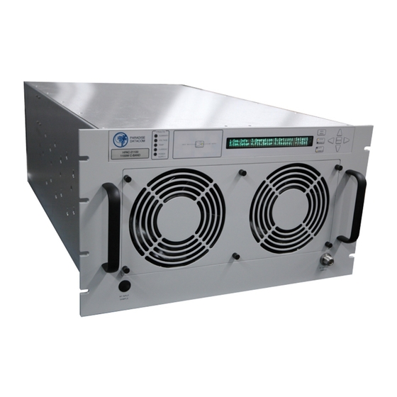
Section 1: General Information 1.0 Introduction This section provides the general information for the Teledyne Paradise Datacom 6-Rack Unit Solid State Power Amplifier (SSPA) Chassis. This includes a description of the unit and safety precautions. 1.1 Description The indoor rack mounted unit contains an internal microprocessor which allows for full monitoring and control from the front panel’s 2x40 Vacuum Florescent Display and... -
Page 12: Specifications
Perform a visual inspection of the equipment to make sure that all items on the packing list are enclosed. If any damage has occurred or if items are missing, contact: Teledyne Paradise Datacom 328 Innovation Blvd., Suite 100 State College, PA 16803 USA... -
Page 13: Safety Considerations
1.7 Safety Considerations Potential safety hazards exist unless proper precautions are observed when working with this unit. To ensure safe operation, users must follow the information, cautions and warnings provided in the manual, and the warning labels placed on the unit itself. 1.7.1 High Voltage Hazards High Voltage for the purpose of this section is any voltage in excess of 30 volts. -
Page 14: Rf Transmission Hazards
• Operators should be familiar with procedures to employ in the event of an emergency, i.e., remove all power, CPR, etc. Large DC currents are generated to operate the RF Module inside of the enclosure. EXTREME CAUTION IS REQUIRED WHEN THE ENCLOSURE IS OPEN AND THE AMPLIFIER IS OPERATING. -
Page 15: Section 2: Operation Of Stand-Alone Unit
Section 2: Operation of Stand-Alone Unit 2.0 Introduction This section contains operating information including a description of the front panel indicators and controls, and I/O connectors and their functions. 2.1 Description of SSPA Controls, Indicators and Connectors 2.1.1 Front Panel Features The 6RU RM SSPA has 10 LEDs to indicate the internal state of the amplifier. -
Page 16: Vacuum Florescent Display (Vfd)
2.1.1.1 Vacuum Florescent Display (VFD) The front panel 40x2 character VFD allows the user to get detailed information about the state of the HPA and provides easy customization of operation through an interactive menu structure. The menu structure is shown in Figure 2-11. 2.1.1.2 Navigation Keys Up, Down, Left, Right and Enter keys on the right side of the front panel allow menu navigation. -
Page 17: Rear Panel Features
Figure 2-2: 6 RU SSPA Chassis Rear Panel 2.1.2 Rear Panel Features Figure 2-2 shows a typical outline drawing of the rear panel view. 2.1.2.1 RF Input Port (J1) [Type N(F)] The type N female connector on the right side of the rear panel is used for RF input. Note: Maximum RF Input Power of +15 dBm. -
Page 18: Serial Main (J4) [Db9(F)]
Table 2-1: Switch Port (J3) pin outs Pin # Function / Description +28V Switch Drive Output. 3 Amp over current protection. Switch 1 Position 2 drive Switch 1 Position 1 drive +28V Switch Drive Output. 3 Amp over current protection. Switch 2 Position 2 drive Switch 2 Position 1 drive 2.1.2.4 Serial Main (J4) [DB9(F)]... -
Page 19: Parallel I/O Port (J7) [Db37(F)]
2.1.2.7 Parallel I/O Port (J7) [DB37(F)] A DB37 female type connector, the Parallel I/O Port contains a series of contact closures for monitoring HPA faults as well as opto-isolated inputs for controlling some HPA functions. Inputs react on the closure to ground. The minimal closure time is 50 mS. -
Page 20: Hardware Mute (Tx Enable)
2.1.2.7.1 Hardware Mute (Tx Enable) There are three ways to mute the amplifier via hardware input: 1. A 50 ms closure to ground on Port J7, Pin 17 toggles between Mute/Unmute states; 2. Press the Main Menu key; select 4.Fault Setup and press the Enter key; select 2.Auxiliary Faults and press the Enter key;... -
Page 21: Power Supply M&C (J12)
Note: IP address, Gateway address, Subnet mask, IP port and IP Lock address needs to be properly selected prior to first use (see Appendix C for details). LED lamps on the connector indicate network status. A steady Green light indicates a valid Ethernet link;... -
Page 22: Figure 2-4: 1Ru Power Supply Ac Line Inputs/Outputs
The power supply module removal can be performed with the system powered. This is to say that the modules are “hot swappable”. In keeping with the redundant architecture of the power supply, there are individual AC inputs for each power supply module. DC Outputs are in a bus bar configuration. See Figure 2-4. -
Page 23: Ac Mains Connection
2.2.1 AC Mains Connection The AC mains connection to the power supply chassis is provided by a terminal block connection for each power supply module in the chassis. See Figure 2-6. Figure 2-6: Power Supply AC Input Wiring Connect your first line/hot to L1, your second line or neutral to L2/N, and finally your AC ground to GRD. -
Page 24: Power Supply Module Alarm Connection
The DC connections from the power supply are made by an in-line threaded terminal connection. Verify the polarity of connections before powering units on. Outputs are labeled "+" for positive and "-" for negative. A DC reference ground should be connect- ed to the appropriate output for desired polarity of the system. -
Page 25: Menus
2.3 Menus Figure 2-9 shows the Front Panel Display Menu Structure hierarchy. There are six main levels of menu selections. • Sys.Info - System Information menu sublevel (See Section 2.3.1) • Com.Setup - Serial Communication related settings (See Section 2.3.2) •... -
Page 26: System Information Sub-Menu
PS:XXXXXX LowRF:XXXXXX Fan:XXXXXX Main AUX:XXXXXX VSWR:XXXXXX BUC:XXXXXX 3.Operation 1.Info Menu SSPA Firmware Info RFSW1:XXXXXX State:XXXXXX Prior:XXXX RFSW2:XXXXXX Mute:XXXXXX PolSel:XXXX Teledyne Paradise Datacom LLC Digicore X Version X.XX (XX) Built YYYY.MM.DD Prtcl:XXXXXX Intrfc:XXXXX Buzzer:XXX Baud:XXXXX Addrs.:XXX Latch:XXX SSPAID:XXXXXXXXXXXXXXXXXXXX UserInfo:XXXXXXXXXXXXXXXXXXXX Mode:XXXXXXX Ctrl:XXXXXX... -
Page 27: Sys Info
The user can also browse among these pages by navigating the cursor around the menu fields and pressing the Enter button on the keypad. Note that this function will not work if the “Fault Latch” option is selected. In a N+1 configuration, the Master unit default System Information page is as described in Section 2.3.1.16;... -
Page 28: Sys Info
2.3.1.2 Sys Info Page 2 This page shows a variety of alarm states which may be present within the HPA. Fault values could be “FAULT!”, “Normal” and “N/A”. If the fault condition doesn't apply to the HPA it will display “N/A” for “Not Available”. •... -
Page 29: Sys Info
2.3.1.5 Sys Info Page 5 Page 5 shows settings related to the HPA 1:1 Redundant System operation. • Mode — Indicates HPA operational mode. See Section 2.3.3.4. • Stby. — Shows the HPA standby state selection. “Hot” - Hot standby op- eration (HPA retains unmuted state during standby);... -
Page 30: Sys Info
2.3.1.8 Sys Info Page 8 This page shows individual RF module states in multi-module HPAs. • Mod# & PreAmp — Mod1 to Mod4 represent the overall state of the rel- evant RF Power modules. If the amplifier is equipped with a separate -amplifier module, the “PreAmp”... -
Page 31: Sys Info Page 10 (Version 6.00)
2.3.1.10 Sys Info Page 10 (version 6.00) The page shows advanced fault analysis information and advanced N+1 operation fea- tures. • MuteFault – This parameter allows the user to check the SSPA mute condition. Possible values: ○ Clear — No present fault mute condition on SSPA unit. Mute/Unmute function under full user control;... -
Page 32: Ip Info
2.3.1.11 IP Info Page 1 This page is available through the Comm. Setup menu, and shows SSPA settings re- lated to the IP interface. • IP Address – IP address of the SSPA. Consult your network administra- tor to set this address according to your LAN configuration. •... -
Page 33: Ip Info
2.3.1.14 IP Info Page 4 This page contains information about the web password and Trap NMSIP. • WebPassword — Indicates the selected password for the web page in- terface. A blank value indicates that the web interface does not require a password protected login. -
Page 34: Hpa Run Time Page 10 (Version 6.00)
2.3.1.20 HPA Run Time Page 10 (version 6.00) This page shows the days, hours, minutes and seconds since the unit was last pow- ered up. 2.3.1.21 N+1 Master Info Page 1 This page can only be viewed when the SSPA unit is configured as the N+1 Master unit. -
Page 35: Clear Faults Menu
2.3.1.21.1 Clear Faults Menu This page allows user to clear latched faults conditions, if the Fault Latch option is ena- bled. • 1.Clear Faults — When selected, all latched fault conditions are cleared. Also Master N+1 unit fault history and SNMP trap history will be cleared when “Clear Faults”... -
Page 36: N+1 Master Info
2.3.1.23 N+1 Master Info Page 2 This page displays additional N+1 system operation data, and can be accessed by pressing the Up Arrow (▲) key from the N+1 Master Info Page 1. This page is only accessible from the N+1 Master unit. •... -
Page 37: Communication Setup Sub-Menu
Main Menu 1.Sys Info 2.Com Setup 3.Operation 4.Flt. Setup 5.Options 6.Redundancy 1.Protocol 2.Baud Rate 3.SysAddress 4.Interface 5.IP Setup 6.N+1Cntrl 1 .. 255 1.Normal 2.Terminal 1.2400 2.4800 3.9600 4.19200 5.38400 1.RS232 2.RS485 3.IPNet 4.SNMP To IP Info Page 1.IPInfo 2.LocalIP 3.Subnet 4.Gateway 5.LocalPort 6.More... -
Page 38: System Address
2.3.2.3 System Address Sets the network address of the controller if used on a RS-485 network. Choose 1-255. The factory default address is 0. Note: Changes in serial communication settings from the front panel are effective immediately. Changes to these parameters from serial interface require that the unit be reset in order to take effect. -
Page 39: More (Snmp, Ip And Web Settings)
2.3.2.5.1 More (SNMP, IP and Web Settings) This menu allows the user to set the Community String Selection (Set/Get) and assign the Web Password. Use the Up Arrow [▲] and Down Arrow [▼] keys to browse through selected charac- ters. Press the Up Arrow [▲] and Down Arrow [▼] keys simultaneously to erase the selected character. -
Page 40: More (Traps And Time Settings)
• 5.More — This selection opens the menu items listed in Section 2.3.2.5.2. • 6.Back — This selection opens the menu items listed in Section 2.3.2.5. 2.3.2.5.2 More (Traps and Time Settings) This menu allows the user to set SNMP Trap settings, and also set the time of the in- ternal clock. -
Page 41: N+1 Control (Floating Master Mode)
2.3.2.6 N+1 Control (Floating Master Mode) This menu allows the user to set parameters relating to Floating N+1 Master operation. This feature allows having a single point of control for an N+1 system Master Module. When enabled, this mode will switch the N+1 Master Module serial and IP address to a dedicated floating Master IP and serial address. - Page 42 • Floating Master mode needs to be disabled if network switches utilize static ARP tables or if dynamic IP changes are forbidden. Use of a dedicated serial Master address is optional, but desirable. Menu selections include: • 1.MasterIP Enable — This selection enables Floating Master Control mode;...
-
Page 43: Operation Setup Sub-Menu
Main Menu 1.Sys Info 2.Com Setup 3.Operation 4.Flt. Setup 5.Options 6.Redundancy 1.Info 2.Buzzer 3.Mute 4.Sys.Mode 5.Attenuation 6.RF Units To SSPA Firmware Info Page 1.dBms 2. Watts 1.Mute On 2.Mute Off 0.0 .. 20.0 dB 1.Buzzer On 2.Buzzer Off 1.StdAlone 2. 1:1 Mode 3. -
Page 44: Attenuation
• 1:2PhComb – This mode is similar to 1:2 mode, but is used to combine two SSPA outputs rather than supplying a signal for two separate polari- zations. Use of N+1 controls in conjunction is highly recommended. • SinglSw – This SSPA mode allows the control of a maintenance switch connected to the output of single SSPA unit. -
Page 45: Fault Monitoring Setup Sub-Menu
Main Menu 1.Sys Info 2.Com Setup 3.Operation 4.Flt. Setup 5.Options 6.Redundancy MENU ITEM NOT ACTIVE UNDER N+1 OPERATION 1.BUC Fault 2. Aux. Faults 3. RFSw Faults 4.Fault Latch 5.Fwd RF / ALC 1.Action (BUC) 2.Logic (BUC) 1.Action (AUX) 2.Logic (AUX) 1.Latch Enb. -
Page 46: Rf Switch Faults
2.3.4.3 RF Switch Faults Determines whether a switch fault should cause a major alarm and attempt to switch, or simply show an alert on the front panel, the latter case considered a minor alarm. • 1.Fault — This is the Major Alarm mode. Summary alarm on fault; •... -
Page 47: High Rf
2.3.4.5.3 High RF When this menu item is selected, an alarm is triggered when the RF output power rises above a threshold value, which is adjustable by the operator (see Section 2.3.4.5.5). This function is available in units with firmware version 6.14 and above. The operator may set the fault handling to trigger either a Major Fault (Fault), Major Fault with Mute, or Minor Fault (Alarm). -
Page 48: Set Level
The ALC has the ability to accurately control the RF output power over a 15 dB range from P . The ALC will operate over a 20 dB range, but the accuracy of the last 5 dB will suffer. For example, if the saturated power from the amplifier is 59 dBm, the lowest accurate power setting during ALC control is 44 dBm. -
Page 49: Options Sub-Menu
Main Menu 1.Sys Info 2.Com Setup 3.Operation 4.Flt. Setup 5.Options 6.Redundancy 1.Backup 2.Restore 3.Lamp Test 4.Password 5.Fan Speed 6.Reset 1.Backup User1 2.Backup User2 3.Back Press Enter 1.Restore User1 2.Restore User2 3.Restore Fctry 4.Back 1.Set 2.Clear 3.Change 4.Back 0..255 1.Low 2.High 3.Auto 4.Back 1.I/O Card Only... -
Page 50: Lamp Test
2.3.5.3 Lamp Test This selection activates all LED indicators on the front panel, including the Fault Indicators, Online Indicator, Local/Remote key and Auto/Manual key. Press the En- ter key to exit the Lamp Test. 2.3.5.4 Password Allows the user to set, clear, or change a password that prohibits others from changing controller settings. -
Page 51: Reset
2.3.5.6 Reset Allows the user to reset the SSPA controller hardware to activate certain settings. For example, when the IP Address is modified the SSPA must be reset for it to use the new IP Address. Firmware version 6.00 allows multiple reset levels for SSPA unit: 1. - Page 52 ing write cycles limit, the SSPA will operate in RAM mode, uti- lizing a default set of settings on each power up. Firmware ver- sion above 6.00 allows 3,000,000 minimum write cycles before opting out to RAM mode; 6. Back — Select this item to return to the Options Sub-Menu (Section 2.3.5). 202058 REV AA 6 RU SSPA Chassis Operations Manual...
-
Page 53: Redundancy Sub-Menu
Main Menu 1.Sys Info 2.Com Setup 3.Operation 4.Flt. Setup 5.Options 6.Redundancy 1.Switching 2. Stdby Select 3. Stdby Mode 4.Status 5.Priority 6.N+1 1.Auto 2.Manual 3.SwLock 1.HPA1 2.HPA2 3.HPA3 (1:2) MENU ITEMS NOT ACTIVE 1.Standby 2.Online 1.Hot Stby 2.Cold Stby 1.Pol1 (1:2 only) 2.Pol2 UNLESS IN STANDALONE MODE OR ANY REDUNDANT MODE WITH... -
Page 54: Status
2.3.6.4 Status Allows user to select between HPA1, HPA2 and HPA3. In 1:1 and 1:2 redundant sys- tems, HPA2 is typically the standby amplifier. 2.3.6.5 Priority For use in 1:2 redundant systems. Allows the user to select Polarity 1 or Polarity 2. If the online amplifiers for Polarity 1 and Polarity 2 simultaneously enter a faulted state, the standby amplifier will switch to the selected polarity. -
Page 55: N+1 Info
• 2.AutoGain Off — When Auto Gain is disabled, the system can be ad- justed as if it was a single SSPA unit, attenuating system gain between 0 and 20 dBm. System gain will not apply automatic gain compensation if any of the units in the N+1 redundancy array fails. -
Page 56: Module Eject
• 2.Fault Cause — Master unit only. Displays the cause for the last detect- ed N+1 unit fault. Possible values include “None,” for no faults; “Timeout,” if a Slave unit fails to respond to a Master request for three (3) consecutive queries;... -
Page 57: N+1 Operational Basics (Single Unit)
2.4 N+1 Operational Basics (Single Unit) A single SSPA unit may be operated in N+1 mode in order to take advantage of the Auto Gain Control features described in Section 2.3.6.6.3. In this case, each SSPA module within the SSPA chassis is counted as a separate N+1 entity. For example, a two-module 4RU chassis acts like a two-way N+1 array. -
Page 58: Figure 2-18: Front Panel Display, Master Unit (Online Indicator Illuminated)
If the Master unit develops any kind of major fault condition, it delegates its Master privileges to the unit which is next in N+1 ranking and becomes a slave unit. This type of control architecture eliminates a single point of failure and achieves true N+1 system redundancy. -
Page 59: Controlling System Operation
2.5.2 Controlling System Operation The N+1 system is under the control of the Master SSPA unit at all times. Any system- wide settings changes (local or remote) need to be performed on the Master unit. If a setting is adjusted on a Slave unit, the Master unit will erase and override it with the current system setting. -
Page 60: Adjust System Gain
2.5.4 Adjust System Gain Nominal system gain with Auto Gain enabled is 65 dB; nominal system gain with Auto Gain disabled is 70 dB. Nominal system gain is 70 dB ± 2 dB. To adjust the gain of the system, press the Main Menu key of the Master Module, select 3.Operation and press the Enter key;... -
Page 61: N+1 Rf Power Measurements
2.5.6 N+1 RF Power Measurements The N+1 system may be equipped with a dedicated RF power measurement unit. The RF Power Detector provides RMS measurement of Forward and Reflected RF power directly at the output waveguide and this reading is acquired by the N+1 Master unit. Besides N+1 system level power detection, each individual SSPA unit may be equipped with its own RF power detector. -
Page 62: Reflected Power Monitor Option
Note: All Paradise Datacom SSPAs are protected from short-term 100% reflected power conditions. Teledyne Paradise Datacom does not recom- mend operating the amplifier under a sustained condition of 100% reflect- ed power. The addition of the reflected power sensor option allows the operator to monitor the amount of reflected power on the amplifier for the purposes of identifying issues with the transmission signal. -
Page 63: Section 3: Troubleshooting And Maintenance
Section 3: Troubleshooting and Maintenance 3.0 Troubleshooting Faults The Rack Mount SSPA has five fault condition LEDs on left side of the front panel which reflect a summary fault, and fault states for voltage, temperature, current and the amplifier’s power supply. Additional fault reporting is available via the front panel readout. -
Page 64: Current Fault
3.0.4 Current Fault In the case of a current fault, the user should check the current displayed on page 6 of the system information menu of the front panel display. If the amplifier is in the mute state, current drops within a range of 0 to 5 A. 3.0.5 Power Supply Fault In the case of a power supply fault, follow the steps below: •... -
Page 65: Fan Fault
3.0.7 Fan Fault In the case of a fan fault, follow the tips below. A fan fault is not a Summary fault. • Inspect the fans. • The user should check the booster board voltages on the front panel dis- play. -
Page 66: Set Sspa Spare Module Network Address
Once the cover or base are removed, disconnect the power cables from each SSPA module. Also disconnect the semi-rigid waveguide connections on the RF IN, Sample and optional Reflected Power ports. Lastly, remove the four (4) 4-40 x 3/8” socket head cap screws, with lock and flat washers, that secure the M&C ribbon cable to each module, and disconnect the ribbon cable from the M&C port. -
Page 67: Phase Adjustment
Figure 3-3: Set Amplifier Network Address 3.1.1.2 Phase Adjustment The phase adjustment of the amplifier’s original module configuration (for optimum output power across the frequency range) was completed at the factory prior to shipment. In the event that an original SSPA module fails and is replaced with another module with a slightly different phase, the amplifier will need to be adjusted for best performance. -
Page 68: Removable Controller Card (Rear Panel)
Figure 3-4: SSPA Module Phase Adjuster Knob Locations 3.1.2 Removable Controller Card (rear panel) The SSPA Controller card is a removable assembly located at the rear of the SSPA. The controller card includes connections for the Switch (J3), Serial Main (J4), Serial Local (J5), Programming (J6), Parallel I/O (J7), Link (J8) and Ethernet (J9) ports. -
Page 69: Firmware Upgrade Procedure
3.1.3 Firmware Upgrade Procedure Teledyne Paradise Datacom’s digital engineers continually strive to improve the perfor- mance of RM SSPA software and firmware. As this occurs, software and firmware up- grades are made available. -
Page 70: Web Upgrade Procedure
SSPA USB programming port. • SSPA field programing utility. Contact Teledyne Paradise Datacom tech- nical support to obtain the latest version. The Field Programming utility is typically not required for installation. • Firmware image upgrade file: code.bin. 3.1.3.3 Web Upgrade Procedure The web upgrade is the preferred method of upgrading the HPA firmware. -
Page 71: Figure 3-9: Proceed With Upgrade Prompt
5. Click the “Upload” button. A warning message will appear; click the “OK” but- ton (See Figure 3-9). Figure 3-9: Proceed With Upgrade Prompt 6. The upload process will begin and the form will be informing about loading process (See Figure 3-10). Do not interrupt this process and wait until its completion with positive or negative result. -
Page 72: Usb Port Upgrade Procedure
3.1.3.4 USB Port Upgrade Procedure 1. Contact Teledyne Paradise Datacom support to obtain the latest firmware image and field programing utility. The programming utility package includes an RFU upload utility, a script file and FTDI USB drivers. Use the USB up- grade method only if the web upgrade has failed! 2. -
Page 73: Removable Fans
The intake and exhaust fan assemblies can be easily replaced with minimal inter- ruption of service. Replacement fans are available from Teledyne Paradise Data- com. The front panel (intake) fan tray is se- cured by six captive thumb screws. To... -
Page 74: Changing N+1 Hierarchy
3.2 Changing N+1 Hierarchy Normally, the hierarchical structure of the N+1 array must be set during initial system setup. However, the operator may change the N+1 addressing hierarchy at any time. To ensure uninterruptible system operation during such system maintenance, certain procedural steps must be followed. -
Page 75: Add An Sspa Unit To The System
3.2.3 Add an SSPA Unit to the System If one of the SSPA units was removed from the system or it down for maintenance, adding it back to system array may cause an unexpected change to a system state. To provide uninterruptible system operation, follow the procedure below. -
Page 76: System Gain And Power Vs. Number Of Modules In System
3.3 System Gain and Power vs. Number of Modules in System With parallel system architectures the amplifier output power capability and gain will change as the number of active modules varies. The 6RU SSPA chassis is designed so that the overall system gain will remain constant in the event of a single module failure. -
Page 77: Section 4: Rf Architecture
Section 4: RF Architecture 4.0 Introduction The basic RF architecture of the SSPA chassis is based on a modular design ap- proach. Four SSPA modules are phase combined to achieve the output power capabil- ity. Each SSPA module is a complete system. It is comprised of a 75 dB gain amplifier complete with a high gain SSPA adjustable from 55 to 75 dB, a communication bus and embedded controller. -
Page 78: Intermodulation Distortion
Satcom system. Teledyne Paradise Datacom recognizes the importance of this back-off characteristic and provides a plot of back-off Vs IMD from 1 dB to 10 dB back from the amplifier’s compression point. -
Page 79: Multi-Carrier Intermod Performance
4.2 Multi-Carrier Intermod Performance The SSPA typically performs better under multicarrier environments than does a Trav- eling Wave Tube Amplifier (TWTA). This is to say that the TWTA must waste a greater percentage of its output power capability to achieve acceptable distortion levels. Tech- niques such as pre-distortion linearization can improve the TWTA response to a degree, but the SSPA is typically still superior. -
Page 80: Mute/Un-Mute Switch Time
The multi-carrier operating environment is further complicated by the number of carriers that are transmitted through the amplifier. The largest degradation in distortion occurs when going from two carriers to three carriers. Figure 4-4 shows the intermod performance vs. number of carriers for 2, 3, 6, and 10 carriers. As the figure shows after approximately 10 carriers the intermod performance flattens and approaches that of a noise power ratio (white noise) performance. -
Page 81: Section 5: 1:1 Redundant System Operation
Section 5: 1:1 Redundant System Operation 5.0 Introduction This chapter describes how to configure and control a 1:1 redundant system, which consists of two Paradise Datacom High Power RM SSPAs and a waveguide/coaxial switch. Two High Power RM SSPA units can be connected in a 1:1 redundant configuration, which can automatically switch to an operating amplifier if the on-line SSPA develops a system fault. -
Page 82: Figure 5-2: Outline Drawing, 6Ru Sspa 1:1 Redundant System
Figure 5-2: Outline Drawing, 6RU SSPA 1:1 Redundant System 202058 REV AA 6 RU SSPA Chassis Operations Manual... -
Page 83: Hardware
Both SSPAs constantly monitor the waveguide switch position. The proper position for the online SSPA is determined by the “Unit Status” setting. If the selected SSPA is configured as “HPA1,” it will drive the RF switch to Position 1 to set itself to the on-line state. -
Page 84: Link Cable
Table 5-1: RF Switch Connector Wiring HPA1, P2 HPA2, P3 RF Switch, P1 Description Common +28V Pos 1 Pos 2 Figure 5-3: Outline Drawing, Switch Connector Cable 5.1.4 Link Cable The 9 pin socket J8 connector Link Port is used to link two Redundant SSPAs in order to pass online/standby status information between them. -
Page 85: Fuses
5.1.5 Fuses The Paradise Datacom RM SSPA is designed to be maintenance free. The 28V switch voltage is protected electronically against shorts and over-voltage conditions, therefore no fuses are needed. 5.2 Installation and SSPA Configuration The two RM SSPA units are designed to be installed in a standard EIA rack. Warning: Ensure the equipment rack is properly supported to prevent tipping forward when the amplifiers are extended on their slides. -
Page 86: Online / Standby Amplifier Selection
Figure 5-5: “Unit 1” Indicator from Front Panel 5.2.2 Online / Standby Amplifier Selection To instantly determine the on-line state of a particular SSPA, check the Unit 1 key on the front panel keypad (See Figure 5-5). It should be illuminated if the SSPA is online. To put the SSPA in standby mode, press the Unit 1 key and the light should go off. -
Page 87: Physically Rotating Transfer Switch
5.2.4 Physically Rotating Transfer Switch It is possible to physically rotate the shaft on the transfer switch to change the online and standby amplifiers positions. This can be done either in manual or automatic mode. When the switch is physically rotated in automatic mode the online SSPA will attempt to return the switch to its previous position. -
Page 88: Parallel Port Special Functions
5.2.6 Parallel Port Special Functions In 1:1 Redundant Mode, each SSPA chassis will change some of its parallel I/O functions to alternative functions. See Table 5-3 for details. Table 5-3: Parallel Connector, Highlighting 1:1 Functions Pin # Function / Description Closed on Power Supply Fault Form C relay NC Open on Power Supply Fault Form C relay NO Power Supply Fault Common... -
Page 89: Section 6: Internal 1:2 Redundant System Operation
Operation of a 1:2 system with controller is more fully discussed in the Redundant Systems Controller Operations Manual, document number 205933. Teledyne Paradise Datacom also offers an internal 1:2 redundancy system, where the extra controller is not required and the state of the system is negotiated between all three HPAs over the redundancy link and switch cables. -
Page 90: Required Hardware
6.1 Required hardware • Three Teledyne Paradise Datacom RM SSPAs with controller card firm- ware revision better than 2.50 and I/O card version better than 1. Internal 1:2 redundancy mode for earlier hardware/firmware revisions is not avail- able. -
Page 91: Power Supply
6.2 Power Supply Each SSPA utilizes a separate external power supply. The standard power supply is a 1RU high, 19-inch rack-mountable unit consisting of up to four 2.5 kW modules. This configuration allows redundancy on the power supply for amplifiers requiring up to 10 kW of maximum DC power. -
Page 92: Link Cable
6.5 Link Cable The 9-pin male connector J8 Link Port is used to link an HPA with the other two redun- dant units in order to pass online/standby status information between them. The link cable is an asymmetrical crossover cable. Take care to match the labels on each cable with the HPA status of the units (i.e., plug cable end with label “HPA1”... -
Page 93: Fuses
Figure 6-4: 1:2 System Wiring Diagram 6.6 Fuses The Paradise Datacom LLC RM SSPA is designed to be maintenance free. The 28V Switch voltage is protected electronically against shorts and over-voltage conditions, therefore no fuses are needed. 6 RU SSPA Chassis Operations Manual 202058 REV AA... -
Page 94: Installation And Sspa Configuration
6.7 Installation and SSPA Configuration 6.7.1 Installation All three SSPA units are designed to be installed in a standard EIA rack. Warning! Ensure the equipment rack is properly supported to pre- vent tipping forward when the SSPAs are extended on their slides. HPA1 should be located on the top of the rack, HPA2 should be located directly below HPA1 and HPA3 should be located below HPA2. -
Page 95: Setting Sspa's Polarization Priority
6.7.2 Setting SSPA’s Polarization Priority Polarization priority selection becomes critical in the case when two out of the three SSPAs have developed summary faults. In this occasion, the remaining online SSPA may redirect its output to support either polarization. This setting applies only to HPA1 and HPA2 units. -
Page 96: Auto Versus Manual Switching Mode
6.9 Auto Versus Manual Switching Mode Normal operating mode for a RM SSPA in 1:2 redundant configuration is “Auto”. This mode provides automatic detection of a SSPA fault and switchover to the operational SSPA. The system is also protected from operator error; selecting a faulted SSPA is not allowed. -
Page 97: Section 7: Internal 1:2 Phase Combined Mode Operation
Section 7: Internal 1:2 Phase Combined Mode Operation 7.0 General Information Teledyne Paradise Datacom 6RU SSPA units running firmware version 4.99 or later can be configured to form an internally controlled 1:2 Phase Combined redundancy system. This configuration provides switching and fault analysis logic as well as simultaneous mute and attenuation control of the three system SSPAs without the use of an external controller. -
Page 98: Figure 7-2: System Mimic Path Display, Hpa1 & Hpa3 Online; Hpa2 In Standby
In normal operation, HPA1 and HPA3 are online, with HPA2 in standby mode. See Figure 7-2. An online SSPA can be placed in standby mode be pressing the front pan- el “Unit 1” button. If the reserved SSPA is in a fault-free condition, or if operation mode is set to “Manual”, the reserved SSPA will assume online mode and the current unit will assume the standby state. -
Page 99: Placing Hpa1 In Standby Mode
If N+1 mode is properly enabled, the entire system can be operated from the Master Module (see N+1 section for details on identifying Master unit). Changes to Mute and Attenuation and certain other settings (as detailed in Section 2.5) made on the Master Module will be automatically propagated to other SSPAs in the system. -
Page 100: Placing Hpa3 In Standby Mode
7.1.2 Placing HPA3 in Standby Mode To switch HPA3 into Standby Mode, press the “Unit 1” key on the front panel of HPA3. If the unit is in “Auto” switching mode, and if HPA2 is not in a fault condition, the posi- tion of SW1 will change to direct the output of HPA3 to the termination and the output of HPA2 into the waveguide combiner. -
Page 101: Setting Internal 1:2 Phase Combined Mode
7.2 Setting Internal 1:2 Phase Combined Mode To enable the system switch control logic, all SSPA units need to be configured for 1:2 Phase Combined mode. This can be done remotely or via the front panel interface. Optionally, if the operator wants to control the system as if it were a single amplifier, N+1 mode has to be turned on to allow a single point of control for system wide attenu- ation and mute status. -
Page 102: Setting N+1 Gain Control
7.2.2.2 Setting N+1 Gain Control Select N+1 gain control option to “Keep Alive” mode by entering the following on the front panel menu: 1. Press the Main Menu key; 2. Select 6.Redund. and press the Enter key; 3. Select 6.N+1 and press the Enter key; 4. -
Page 103: Assign Hpa2 N+1 Address
7.2.2.4.2 Assign HPA2 N+1 Address 1. Press the Main Menu key; 2. Select 6.Redund. and press the Enter key; 3. Select 6.N+1 and press the Enter key; 4. Select 2.N+1 Address and press the Enter key. If the unit is a single module chassis, assign Address 002 and press the Enter key. -
Page 104: Setting Hot/Cold Standby Mode
7.2.4 Setting Hot/Cold Standby Mode If Hot standby mode is desired, where the offline SSPA remains unmuted, enter the following for each SSPA in the system: 1. Press the Main Menu key; 2. Select 6.Redund. and press the Enter key; 3. -
Page 105: Section 8: L-Band Operation
Section 8: L-Band Operation 8.0 Block Up Converter Overview Teledyne Paradise Datacom SSPAs are available with various L-Band up converter options. The primary up converter option is the Zero dBm Block Up Converter, zBUC. ® The zBUC converter is offered in four C-Band configurations, two Ku-Band options, and one X-Band model. -
Page 106: Figure 8-2: Schematic, Optional Block Up Converter
TO SSPA MODULE RF INPUT Figure 8-2: Schematic, Optional Block Up Converter The schematic of Figure 8-2 shows the electrical position of the block up converter. It is powered from a +15 VDC supply available from the Back Plane Board Assembly. The Block Up Converter is simply cascaded with the SSPA at the input of the amplifier. -
Page 107: Zbuc Converter Features
8.1 ZBUC Converter Features This section describes the features available in the Teledyne Paradise Datacom ® zBUC converter. The zBUC converter is available as an option for the SSPA. The zBUC converter is available in four C-Band models, two Ku-Band models and one X-Band model. -
Page 108: Smart Reference Technology
8.3 Smart Reference Technology Teledyne Paradise Datacom’s zBUC converter comes standard with smart reference technology. Smart reference technology allows the system operator to change exter- nal system reference frequency without any system configuration required. The zBUC converter will automatically sense and lock to any one of the following system refer- ence frequencies: 10, 20, 25, and 50 MHz. -
Page 109: Typical System Configuration
8.4 Typical System Configuration This section shows the 6RU Rack Mount SSPB in a common system application. Figure 8-4 shows the amplifier used with a Teledyne Paradise Datacom PD25 Evolu- tion Series L-Band Modem. Figure 8-4: SSPB Chassis with L-Band Modem 8.5 IFL Cable Considerations... - Page 110 THIS PAGE LEFT INTENTIONALLY BLANK 202058 REV AA 6 RU SSPA Chassis Operations Manual...
-
Page 111: Section 9: Remote Control Interface
Section 9: Remote Control Interface 9.0 Overview A system which includes an SSPA can be managed from a remote computer over a variety of remote control interfaces (see Figure 9-1). Figure 9-1: SSPA Remote Control Interface Stack The parallel port on SSPA unit provides a simple form of remote control. There are 10 “dry”... -
Page 112: Table 9-1: Interfaces Enabled Based On Chosen Interface Setting Selection
Serial protocol format for both RS232 and RS485 interfaces is set at no parity, 8 bit, 1 stop bit, no handshaking. If using a Terminal mode protocol, the SSPA provides remote menu access through a HyperTerminal program or through an actual hardware terminal. The Ethernet interface is fixed to the 10Base-T standard. -
Page 113: Remote Control - Parallel
9.1 Remote Control - Parallel 9.1.1 Control Outputs The hardware behind the form C relay is a single pole, double throw relay. Under normal operation (no alarms) the relays are in an energized state. When a fault occurs or the controller is powered off, the relays are in a de-energized state. The relay con- tacts are capable of handling a maximum of 30 VDC @ 1A . -
Page 114: Serial Communication Protocol
9.2 Serial Communication Protocol This section describes the basic serial communication protocol between the SSPA and host computer. The amplifier will only respond to properly formatted protocol packets. The basic communication packet is shown in Figure 9-3. It consists of a Header, Data and Trailer sub-packet. -
Page 115: Data Packet
9.2.2 Data Packet The data sub-packet is comprised of 6 to 32 bytes of information. It is further divided into seven (7) fields as shown in Figure 9-5. The first six (6) fields comprise the com- mand preamble while the last field is the actual data. HEADER DATA TRAILER... -
Page 116: Data Tag
9.2.2.4 Data Tag The data tag specifies the type of internal resource of information needed to be ac- cessed on the amplifier. The data associated with certain tags is read only. Therefore, only the “Get” command byte would be associated with these data tags. The data tag byte values are given in Table 9-3. -
Page 117: Data Length
Table 9-4: Error Status Byte Values Error Code Name Byte Value Possible Cause No Errors Normal Condition, no errors detected Data Frame Too Big Specified Data length is too big for amplifier buffer to accept No Such Data Specified Data Address is out of bounds for this tag data Bad Value Specified value not suitable for this particu-... -
Page 118: Trailer Packet
9.2.3 Trailer Packet 9.2.3.1 Frame Check The trailer component contains only one (1) byte called the Frame Check Sequence, shown in Figure 9-6. HEADER DATA TRAILER (4 bytes) (6-32 bytes) (1 byte) Frame Check Checksum (1 byte) Figure 9-6: Trailer Sub-Packet This field provides a checksum during packet transmission. -
Page 119: Serial Communications Protocol
9.2.5 Serial Communications Protocol Table 9-5 through Table 9-9 detail the various values of the serial communications protocol. Table 9-5: Request Frame Structure Byte position Byte Value (Hex) Description 0xAA Frame Sync 1 0x55 Frame Sync 2 Destination Address -//- Source Address -//- Protocol Version... -
Page 120: Table 9-7: System Setting Details
Table 9-7: System Setting Details Min. Data Data Length Description Limits and valid values Address (bytes) 0 = Reserved; 1 = RM SSPA; 2 = CO SSPA; Device Type 3 = RCP2/FPRC; 4 = RCP2-1000-CO; (read only) 5 = RCP2-1000-RM; 6 = RCP2-1000-RCP; 7 = VSAT BUC=7 (Version 4.00*) 0 = Standalone Mode;... - Page 121 Table 9-7: System Setting Details (continued from previous page) Min. Data Data Length Description Limits and valid values Address (bytes) IP Address Byte 1 (MSB) IP Address Byte 2 IP Address Byte 3 IP Address Byte 4 IP Gateway Byte 1 IP Gateway Byte 2 IP Gateway Byte 3 IP Gateway Byte 4 (LSB)
-
Page 122: Table 9-8: System Threshold Addressing Details (Read Only)
Table 9-8: System Threshold Addressing Details (Read Only) Min. Data Data Length Description Limits and valid values Address (bytes) If RF Units (Table 9-7, Data Address 20) = 0, Forward RF power then 0.1 dBm per 1 value; If RF Units = 1, then 0.1 Watt per 1 value (v. -
Page 123: Table 9-9: System Conditions Addressing Details
Table 9-9: System Conditions Addressing Details Data Length Description Limits and valid values Address (bytes) Summary Fault State 0 = No Fault; 1 = Fault Power Supply Fault 0 = No Fault; 1 = Fault High Temperature Fault 0 = No Fault; 1 = Fault Low Regulator Voltage Fault 0 = No Fault;... - Page 124 Table 9-9: System Conditions Addressing Details (continued) Data Min. Data Description Limits and valid values Address Length (bytes) Cabinet Impeller Fault No Fault = 0; Fault = 1; N/A = 2 (v. 4.40*) N+1 System faults 0 to 15, depending on number of faulted N+1 (for N+1 Master unit only) SSPA units and N+1 array size;...
-
Page 125: Access Sspa Subsystem Through Packet Wrapper Technique
9.3 Access SSPA Subsystem through Packet Wrapper Technique Features introduced in firmware version 4.03 allow send requests directly to a remote SSPA subsystem. In this mode, an RCP unit redirects requests from its Serial Main or Ethernet port to its Local serial port, connected to the SSPA (see Figure 9-7). Packet wrapper requests are associated with longer response times, which have to be ac- counted in the host M&C software. -
Page 126: Example 1 Check Sspa Settings
9.4 Example 1 Check SSPA settings Assumptions: SSPA unit unique network address: 5; PC Host unique network address: 10; Request ID: 111; Unit attached to the serial line; PC request string: Byte Count Value Description Frame Sync Byte 1 Frame Sync Byte 2 Destination Address of Unit Source Address of Request Originating PC Host Protocol Version Compatibility. - Page 127 SSPA response string: Byte Count Value Description Frame Sync Byte 1 Frame Sync Byte 2 Destination Address of PC request originator Source address of the respondent Protocol Version Compatibility Field must be always 0 Echo of the Originator's Request ID byte Command field for “Get”...
-
Page 128: Terminal Mode Serial Protocol For Paradise Datacom Sspa
9.5 Terminal Mode Serial Protocol for Paradise Datacom SSPA The Teledyne Paradise Datacom Rack Mount SSPA utilizes Terminal Mode Serial Pro- tocol (TMSP) as a secondary serial protocol for management and control through a re- mote serial interface. TMSP allows the user to access internal SSPA functions via a remote ASCII Terminal or its equivalent (such as HyperTerminal for Windows). -
Page 129: Figure 9-8: Terminal Mode Session Example
Figure 9-8 shows an example screen shot of a terminal session. Figure 9-8: Terminal Mode Session Example 6 RU SSPA Chassis Operations Manual 202058 REV AA... -
Page 130: Ethernet Interface
IP protocols. In order to keep data bandwidth as low as possible (which is im- portant when M&C functions are provided through a low-bandwidth service channel) the IP/UDP protocol set is used as the Network/Transport layer protocol on Teledyne Paradise Datacom SSPAs. -
Page 131: Figure 9-9: Udp Redirect Frame Example
The number of the retransmissions is user configurable. The Teledyne Paradise Datacom RM SSPA Ethernet IP interface can use UDP ports from 0 to 65553 for sending and receiving. The receiving port needs to be specified through the front panel menu. -
Page 132: Setting Ipnet Interface
This set of Ethernet IP protocols is currently supported by the Teledyne Paradise Data- com Universal M&C software package. The software is supplied on CD with the unit, or can be download from company's web site, http://www.paradisedata.com. 9.6.1.2 Setting IPNet Interface Before enabling the Ethernet IP interface, the following IP parameters need to be set: IP Port address, Default Gateway, Subnet Mask, Receive IP Port and Lock IP address. - Page 133 To disable the Ethernet port and enable the RS-232/RS-485 Serial Main port: 1. Press the Main Menu key; 2. Select 2.Com.Setup and press the Enter key; 3. Select 4.Interface and press the Enter key; 4. Select either 1.RS232 or 2.RS485 and press the Enter key. Important! At present, the RM SSPA controller supports only one remote control protocol selection through its Ethernet interface port.
-
Page 134: Using The Rack Mount Web Interface
9.6.1.3 Using the Rack Mount Web Interface Starting with firmware version 6.00, the rack mount web interface no longer needs to have a pre-installed Java application to operate. The web interfaces uses a standard hypertext transfer protocol on port 80. The web interface is compatible with most mod- ern web browsers, such as Firefox, Chrome or Internet Explorer, which support asyn- chronous JavaScript XML transactions (aka AJAX). -
Page 135: Figure 9-11: Rm Sspa Web Interface, Status Tab
Click on the [Log In] button to open the M&C control in the browser. See Figure 9-11. Figure 9-11: RM SSPA Web Interface, Status Tab The top bar of SSPA Monitor and Control application shows device’s online status, transmit status, RF output power, reflected RF power (if available), attenuation and RF module core temperature. -
Page 136: Snmp Interface
Teledyne Paradise Datacom web site, http://www.paradisedata.com. 9.6.2.1 Interface The Teledyne Paradise Datacom MIB is a table-based MIB, and is the same for all de- vices. The MIB table is designed to follow the same pattern as the tables for serial pro- tocol. - Page 137 Delivery Protocol (DDP), and Novell Internet Packet Exchange (IPX). SNMPv1 is wide- ly used and is the de-facto network-management protocol in the Internet community. The Teledyne Paradise Datacom SSPA family of products utilizes the most popular im- plementation, SNMP V1 over UDP transport layer.
- Page 138 The format of the trap message was also changed in SNMPv2. To avoid these compat- ibility issues, the trap mechanism was not implemented in the Teledyne Paradise Data- com SSPA MIB. SNMP V3 Although SNMPv3 makes no changes to the protocol aside from the addition of crypto- graphic security, it looks much different due to new textual conventions, concepts, and terminology.
-
Page 139: Snmp Mib Tree
9.6.2.3 SNMP MIB Tree --paradiseDatacom(1.3.6.1.4.1.20712) +--deviceINFO(1) +-- r-n OctetString deviceID(1) +-- rwn OctetString deviceLocation(2) +-- r-n OctetString deviceRevision(3) +-- r-n Enumeration deviceType(4) +--devices(2) +--paradiseDevice(1) +--settings(1) +--settingsEntry(1) [settingIndex] +-- rwn Integer32 settingIndex(1) +-- rwn Integer32 settingValue(2) +-- r-n OctetString settingTextValue(3) +--thresholds(2) +--thresholdsEntry(1) [thresholdIndex] +-- rwn Integer32 thresholdIndex(1) -
Page 140: Description Of Mib Entities
9.6.2.4 Description of MIB Entities deviceINFO - This field includes general device information. deviceID - Octet string type; maximum length -60; field specifies device model and serial number; read only access; OID -1.3.6.1.4.1.20712.1.1 deviceLocation - Octet string type; maximum length 60; filed allow customer to store information about device physical location or any other textual information related to the device;... -
Page 141: Table 9-11: Snmp Detailed Settings
Table 9-11: SNMP Detailed Settings 6 RU SSPA Chassis Operations Manual 202058 REV AA... - Page 142 Table 9-11: SNMP Detailed Settings (continued from previous page) 202058 REV AA 6 RU SSPA Chassis Operations Manual...
-
Page 143: Table 9-12: Snmp Detailed Thresholds
Table 9-12: SNMP Detailed Thresholds thresholdIndex/ thresholdTextValue Value OID Descrip on thresholdValue Current value of forward RF 1/INTEGER ForwardRFPower(RFunitsx10)'0..10000 1.3.6.1.4.1.20712.2.1.2.1.2.1 power Current value of reflected 2/INTEGER ReflectedRFPower(RFunitsx10)'0..10000 1.3.6.1.4.1.20712.2.1.2.1.2.2 RF power SSPA DC current con- 3/INTEGER SSPADCCurrent(Ampx10)'0..10000 1.3.6.1.4.1.20712.2.1.2.1.2.3 sumption Power Supply 1 output 4/INTEGER PS1Voltage(Voltx10)'0..200 1.3.6.1.4.1.20712.2.1.2.1.2.4... -
Page 144: Table 9-13: Snmp Detailed Conditions
Table 9-13: SNMP Detailed Conditions conditionIndex/ condi onTextValue Value OID Descrip on conditionValue 1/INTEGER SummaryFault'NoFault=0,Fault=1 1.3.6.1.4.1.20712.2.1.3.1.2.1 Summary fault state 2/INTEGER PowerSupplyFault'NoFault=0,Fault=1 1.3.6.1.4.1.20712.2.1.3.1.2.2 Power supply fault state High Temperature fault 3/INTEGER HighTemperatureFault'NoFault=0,Fault=1 1.3.6.1.4.1.20712.2.1.3.1.2.3 state LowRegulatorVoltageFault'NoFault=0, Low Regulator voltage 4/INTEGER 1.3.6.1.4.1.20712.2.1.3.1.2.4 Fault=1 state Low DC Current fault 5/INTEGER LowDCCurrentFault'NoFault=0,Fault=1... -
Page 145: Configuring Rm Sspa Unit To Work With Snmp Protocol
9.6.2.5 Configuring RM SSPA Unit to Work with SNMP Protocol 1. Set up the unit IP Address. Select the following sequence from the SSPA Front Panel: Press the Main Menu key; select 2.Com.Setup and press the Enter key; select 5.IP Setup and press the Enter key; select 2.LocalIP and press the Enter key. -
Page 146: Connecting To A Mib Browser
9.6.2.6 Connecting to a MIB Browser For a MIB browser application example, we will be using the freeware browser GetIf, version 2.3.1. There are many other MIB browsers available for download from http:// www.snmplink.org/Tools.html. 1. Copy the provided Paradise Datacom LLC MIB file into the Getif Mibs sub- folder. -
Page 147: Figure 9-14: Getif Mbrowser Window, Setting Settingvalue.5 To A Value Of '1
7. Select settingValue.5 entity (SSPA Mute), set the value to 1 and click the Set button. 8. Observe the Mute state on the SSPA change to a “Mute On” state. See Fig- ure 9-14. Figure 9-14: Getif MBrowser Window, Setting settingValue.5 to a Value of ‘1’ 6 RU SSPA Chassis Operations Manual 202058 REV AA... -
Page 148: Extended Snmp Operation
9.6.3 Extended SNMP Operation The 5RU SSPA Chassis is equipped with a DigitalCore5 control board and utilizes firm- ware version 6.00 and above. These units feature an extended SNMP MIB and sup- port SNMP traps. This extended MIB covers several OID objects related to SNMP trap functions. -
Page 149: Extended Snmp Mib Tree
9.6.3.1 Extended SNMP MIB Tree --paradiseDatacom(1.3.6.1.4.1.20712) +--deviceINFO((1.3.6.1.4.1.20712.1) | +-- r-n OctetString deviceID(1.3.6.1.4.1.20712.1.1) | +-- rwn OctetString deviceLocation(1.3.6.1.4.1.20712.1.2) | +-- r-n OctetString deviceRevision(1.3.6.1.4.1.20712.1.3) | +-- r-n Enumeration deviceType(1.3.6.1.4.1.20712.1.4) | +--deviceTimeTicks(1.3.6.1.4.1.20712.1.5) | | | | | +-- r-n TimeTicks deviceUpTime(1.3.6.1.4.1.20712.1.5.1) | | +-- r-n TimeTicks deviceFaultTime(1.3.6.1.4.1.20712.1.5.2) | +--deviceCounters(1.3.6.1.4.1.20712.1.6) | | | | | +-- r-n Counter deviceSFaultCounter(1) - Page 150 +--devices(2) +--paradiseDevice(1) | +--settings(1) | | | | | +--settingsEntry(1) [settingIndex] | | | | | +-- rwn Integer32 settingIndex(1) | | +-- rwn Integer32 settingValue(2) | | +-- r-n OctetString settingTextValue(3) | +--thresholds(2) | | | | | +--thresholdsEntry(1) [thresholdIndex] | | | | | +-- rwn Integer32 thresholdIndex(1) | | +-- r-n Integer32 thresholdValue(2)
-
Page 151: Extended Snmp Mib Tree Elements In Detail
9.6.3.2 Extended SNMP MIB Tree Elements in Detail deviceRevision — Octet string type; maximum length 60; field specifies device firmware revision; read only access; OID -1.3.6.1.4.1.20712.1.3 deviceUpTime — Device total up time in hundredths of a second; deviceFaultTime — Time elapsed since deviceLastFault last state change in hundredths of second;... - Page 152 deviceConditionTrap — Trap fires deviceConditionTrapResend times when value specified by deviceConditionToMonitor is outside of the window specified by deviceConditionULimit and deviceConditionLLimit. In the case of a device with multiple conditions of the same type, specify measurement location in deviceConditionLocation. 202058 REV AA 6 RU SSPA Chassis Operations Manual...
-
Page 153: Appendix A: Ethernet Interface Quick Set-Up
Appendix A: Ethernet Interface Quick Set-Up This section describes the procedure for setting up the RM SSPA Ethernet IP interface through the front panel interface. It also describes basic network setup of a Windows based host PC for a peer-to-peer network connection with the RM SSPA. Important! Do not use a crossover cable to connect to the network hub, use crossover only for direct PC-to-RM SSPA connection! 1. - Page 154 2.4 After optional reboot, open the Command Prompt console window and enter: C:\>IPCONFIG This will display the IP settings: 0 Ethernet Adapter: IP Address: 192.168.0.3 Subnet Mask: 255.255.255.0 Default Gateway: 2.5 You can now try to Ping your PC: In Command Prompt window enter the following: C:\>ping 192.168.0.3 This will display: Pinging 192.168.0.3 with 32 bytes of data:...
- Page 155 4. On the RM SSPA unit front panel, press the Main Menu key; select 2.Com.Setup and press the Enter key; select 4.Interface and press the Enter key; select 3.IPNet and press the Enter key. The RM SSPA is now set up to work with Ethernet Interface. You may now ping the SSPA unit from host PC: C:\>ping 192.168.0.0 This will display:...
- Page 156 THIS PAGE LEFT INTENTIONALLY BLANK 202058 REV AA 6 RU SSPA Chassis Operations Manual...
-
Page 157: Appendix B: Proper 10/100 Base-T Ethernet Cable Wiring
Appendix B: Proper 10/100 Base-T Ethernet Cable Wiring This section briefly describes the basic theory related to the physical layer of 10/100Bas-T networking, as well as proper wiring techniques. There are several classifications of cable used for twisted-pair networks. Recommend- ed cable for all new installations is Category 5 (or CAT 5). -
Page 158: Figure B-3: Ethernet Cable Pin-Outs
The main concern is the transient magnetic fields which surrounds the wires and the magnetic fields generated externally by the other transmission lines in the cable, other network cables, electric motors, fluorescent lights, telephone and electric lines, lightning, etc. This is known as noise. Magnetic fields induce their own pulses in a transmission line, which may literally bury the Ethernet pulses. -
Page 159: Figure B-4: Ethernet Wire Color Code Standards
Figure B-4: Ethernet Wire Color Code Standards Figure B-5: Wiring Using 568A Color Codes There are only two unique cable ends in the preceding diagrams, they correspond to the 568A and 568B RJ-45 jacks and are shown in Figure B-6. 568A CABLE 568B CABLE Figure B-6: Wiring Using 568A and 568B Color Codes... - Page 160 Again, the wires with colored backgrounds may have white stripes and may be denoted that way in diagrams found elsewhere. For example, the green wire may be labeled Green-White. The background color is always specified first. Now, all you need to remember, to properly configure the cables, are the diagrams for the two cable ends and the following rules: •...
-
Page 161: Appendix C: Rm Sspa Control With Paradise Datacom Universal M&C
Appendix C: RM SSPA Control with Paradise Datacom Universal M&C The Teledyne Paradise Datacom Universal M&C software is available for download from the company web site, www.paradisedata.com. Install the software on the computer which will be connected to the system and launch the application. - Page 162 Fill in the appropriate fields depending on the method of communication with the unit. A Unit ID is not required although it is recommended. If a Unit ID isn't entered the Unit ID will be assigned by the M&C. To add a unit connected to a serial port, enter a COM Port, Baud Rate and Amplifier Address.
-
Page 163: Figure C-3: Universal M&C Status Window, Sspa Unit 1
C.1.1 Universal M&C SSPA Status Window As each SSPA unit is added to the Universal M&C, a new window will appear in the screen. The initial screen is the Status Window, as shown in Figure C-3. Figure C-3: Universal M&C Status Window, SSPA Unit 1 The Status window displays the current conditions (or state) of the active unit. -
Page 164: Figure C-4: Universal M&C Settings Window, Sspa Unit 1
C.1.2 Universal M&C SSPA Settings Window The second screen available is the Settings window, shown in Figure C-4. It displays all available settings on the selected SSPA. All user-adjustable settings may be modi- fied to suit the specific needs of the customer. Figure C-4: Universal M&C Settings Window, SSPA Unit 1 The numbers in the square boxes in Figure C-4 represent the Data Addresses for the adjacent setting. -
Page 165: Figure C-5: Universal M&C Fault Status Window, Sspa Unit 1
C.1.3 Universal M&C SSPA Fault Status Window The third screen is the Faults window, shown in Figure C-5. It displays the status of all faults for the selected Rackmount SSPA. In the case of multi-module SSPA units, each RF Module in the amplifier chassis is monitored for faults. If a module is not installed in the SSPA, then it will show up as “N/A”... -
Page 166: Figure C-6: Universal M&C Ip Setup Window, Sspa Unit 1
C.1.4 Universal M&C SSPA IP Setup Window The fourth screen is the "IP Setup" window, shown in Figure C-6. It shows the user all of the TCP/IP settings for the Rackmount SSPA. Note that Figure C-6 shows the Amplifier Selection Tabs for eight (8) SSPAs in an N+1 configuration. Amplifier Selection Tabs Figure C-6: Universal M&C IP Setup Window, SSPA Unit 1 The operator may set the selected unit’s IP Address, Gateway Address and Subnet... - Page 167 The unit’s Media Access Control (MAC) Address is displayed in read-only format on this screen. In addition, the operator may set the Web Password used when utilizing the Web- based M&C. The current password (default is paradise), is displayed. To enter a new password, check the box “Modify Web Password”...
-
Page 168: Figure C-7: Universal M&C Sspa N+1 Window, Master Unit
C.1.5 Universal M&C SSPA N+1 Window The fifth screen available for each SSPA unit is the “N+1” screen. Depending on whether the unit is assigned Master status or Slave status, the N+1 screen will show different information. Figure C-7 shows the display for the Master Module. Figure C-8 shows the display for the Slave units. -
Page 169: Appendix D: Automatic Level Control Operation
Appendix D: Automatic Level Control Operation D.1 Activating Automatic Level Control Automatic Level Control can be activated via the front panel by following the steps listed below: 1. Press the Main Menu key; 2. Select 4.FaultSetup and press the Enter key; 3. - Page 170 D.2 Timing Issues with ALC The ALC circuit is designed to compensate slow and steady drift of input signal and can’t compensate sudden signal level changes. Overall adjustment speed depends on the type of required adjustment. For changes that require more than 5 dBm of level adjustments, ALC performs coarse adjustment first (output signal will be adjusted within ±...
-
Page 171: Appendix E: Documentation
Appendix E: Documentation The following pages comprise the documentation package for the Teledyne Paradise Datacom High Power (6 RU) Solid State Power Amplifier. Specification Sheet: 202059 (check our web site http://www.paradisedata.com for the most recent version of this document); Outline Drawing, specific to your unit;... - Page 172 THIS PAGE LEFT INTENTIONALLY BLANK 202058 REV AA 6 RU SSPA Chassis Operations Manual...
Need help?
Do you have a question about the 6 RU Chassis and is the answer not in the manual?
Questions and answers